Mounting
3-5
SIMATIC Panel PC 670 / 870 Operating Unit, Equipment Manual
Edition 07/02
The clamps and grub screws required for installation are supplied with the
device. Proceed as follows:
1.
Insert the complete operating unit and computing unit into the mounting
cut-out prepared as described in Section 3.1, working from the front.
2.
From the rear, fix the operating unit in position in the mounting cut-out
using the six clamps (see Figure 3-3) by tightening the grub screws (tor-
que 0.4 - 0.5 Nm).
The 12.1” touchscreen version is not suitable for installation with screw fi-
xings. With the other operating units, proceed as follows:
1.
Drill suitable holes around the prepared mounting cut-out (see
Section 3.1) as specified for L4 and L5 in Figure 3-3.
2.
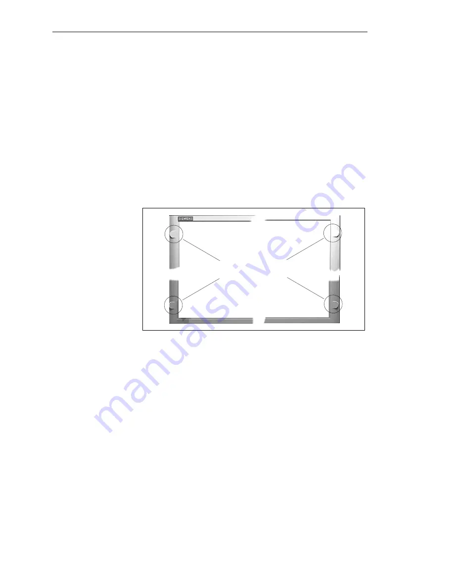
Carefully knock out the drill hole covers on the front side of the opera-
ting unit:
Drill hole covers
3.
Working from the front, insert the complete operating unit and compu-
ting unit into the mounting cutout, ensuring that is flush with the drill ho-
les.
4.
Fix the operating unit at the drill holes using suitable screws and nuts.
Installation with
clamp fixing
Installation with
screw fixing


