UM353-1
Function Blocks
March 2003
3-9
EMER
gency
MAN
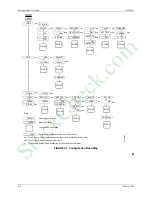
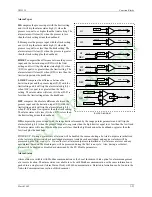
ual will be asserted when input EM is high (1). This causes the output to hold at the last position
and permits the operator to adjust the manual value under the conditions listed for MANual. It will also assert an
EM MAN status, at the configured priority, to the operator display.
STANDBY
will be asserted when input TC is high (1). This causes the A/M block output to track input TV thus
placing the loop in a standby condition. This feature can be used to enable one loop to track another for either
redundancy applications or optional control schemes. It will also assert a STANDBY status, at the configured
priority, to the operator display.
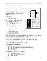
STATUS OUTPUTS -
Output
AS
(Auto Status) goes high (1) when output O1 is the Auto input; output NA will
go high when output 01 is not the Auto input, output MS goes high when the A/M switch is in the manual position;
output ES goes high when the Emergency Manual switch is in the manual position; and SS goes high when the
standby switch is in the Track Variable position. Two LEDs on the display identify the position of the A/M switch.
POWER UP
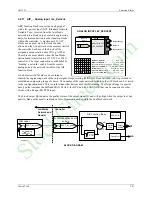
- The A/M function block can be configured to power up under various conditions during a warm or
cold start. If PU LAST has been configured as YES, during a warm start all outputs are initialized at previous values
and the block will power up in the same condition (i.e. same A/M switch position). When powering up in auto, the
A/M block will execute in the manual mode for the first two scan cycles, allowing a controller block to track the last
value. When PU LAST is set to NO, the A/M block does not power up in last position during a warm start and will
power up as configured by the POWER UP parameter, either AUTO or MAN. During a cold start, the A/M block
will always power up as configured by the POWER UP parameter. When the POWER UP parameter is used and
the block powers up in MAN, the manual value can be set using the PU MAN parameter.
C
lock
W
ise
MAN
ual configured as YES, the default position, will cause the manual value to increase with
clockwise rotation of the knob. This feature is useful when clockwise rotation is desired to always open a value
whether the valve is direct or reverse acting.
EM
ergency
MAN
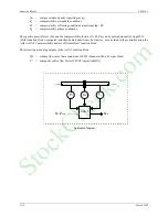
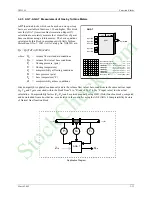
ual, in firmware 1.30 and higher, allows the position of the A/M block Manual Switch (switch 1
in the block diagram) and the associated light to be configured. When the EM input goes high (1), the Emergency
Manual Switch (switch 2) switches to manual. If EM MAN is configured as YES, the Manual Switch (switch 1) and
the indicator light will switch to the manual position, assuming that switch 1 is in Auto, and will remain in the
manual position until the operator presses the A/M button or a command is received from an HMI to switch to Auto.
The EM Switch (switch 2) will remain in the manual position until the EM status clears regardless of the position of
the Manual Switch (switch 1). If the EM MAN parameter is configured as NO, the Manual Switch (switch 1) and
associated indicator light will not change position when the EM input goes high (1).
LOCK MAN
, in V2.4, can be set to YES to lock the loop in manual when Emergency Manual has been activated.
The operator can switch the loop to Auto only when the EM condition has cleared. This feature is available only
when the EM MAN parameter is configured as YES.
The MAN ACCL parameter, in firmware 1.30 and higher, enables setting the acceleration rate applied to the pulser
knob. It can be configured for Slow, Medium, or Fast. Slow is the default and is consistent with firmware versions
less than 1.30.
PRIORITIES -
The priority assigned to EM or SB PRIOR will affect the operation as follows (the outputs ES and
SS will go high with all priority assignments, including 0, when event is active):
1
. Bargraphs, event LEDs, and condition will flash. ACK button must be used to stop flashing.
2
. Bargraphs, event LEDs, and condition will flash. Flashing will stop if ACK or if event clears.
3
. Event LEDs and condition will flash. ACK button must be used to stop flashing.
4
. Event LEDs and condition will flash. Flashing will stop if ACK or event clears.
5
. Event LEDs and condition will turn on when event is active and off when the event clears.
0
. No local display action occurs when event is active.
StockCheck.com
Summary of Contents for Moore 353
Page 2: ...S t o c k C h e c k c o m ...
Page 14: ...Contents UM353 1 xii March 2003 S t o c k C h e c k c o m ...
Page 24: ...Introduction UM353 1 March 2003 1 10 S t o c k C h e c k c o m ...
Page 152: ...LonWorks Communications UM353 1 March 2003 5 4 S t o c k C h e c k c o m ...
Page 164: ...Network Communications UM353 1 6 12 March 2003 S t o c k C h e c k c o m ...
Page 246: ...Operation UM353 1 March 2003 9 8 S t o c k C h e c k c o m ...
Page 254: ...Controller and System Test UM353 1 March 2003 10 8 S t o c k C h e c k c o m ...
Page 282: ...Circuit Description UM353 1 March 2003 13 4 S t o c k C h e c k c o m ...
Page 298: ...Model Designation and Specifications UM353 1 March 2003 14 16 S t o c k C h e c k c o m ...
Page 302: ...Abbreviations And Acronyms UM353 1 15 2 March 2003 S t o c k C h e c k c o m ...
Page 304: ...Warranty UM353 1 W 2 March 2003 S t o c k C h e c k c o m ...

