2
•
Watchdog
when blinking steadily, indicates the MJ-X
L
Communications Module microprocessor and software
are functioning properly.
•
Communications
indicates communications activity with this module. (The Comm Module turns on this
indicator when it receives a valid message with a valid address.)
•
Rxd
indicates the communications module is receiving data.
•
Txd
indicates the communications module is transmitting data.
2 Transmission Methods
There are two transmission mediums available for sending data to the RTU:
•
fiber optic
•
wire
2.1 Fiber Optic Transmission
The primary benefits of fiber optic communications are its immunity to induced electrical interference and
relatively low signal loss. Electrical noise cannot be induced into the cable to generate transient spikes that disrupt
data communications.
The MJ-X
L
Fiber Optic Communications Module uses multi-mode fiber optic cable. The electrical signals are
converted to optical signals by the communication unit. The optical signals are then transmitted via the fiber optic
cable to the RTU. Communications modules in the path between the transmitting communications module and the
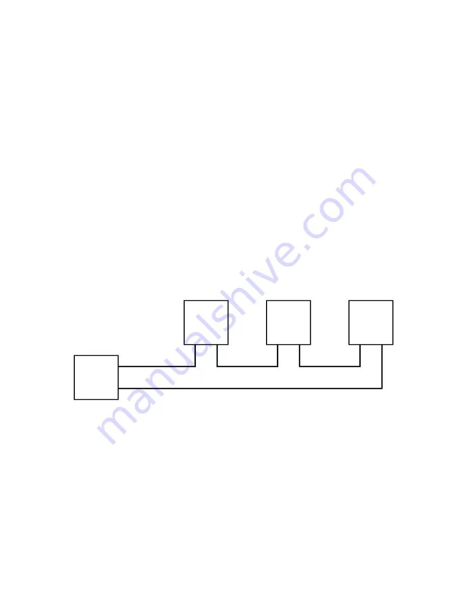
RTU act as repeaters and simply regenerate the signals and forward them to the next device, Figure 2-1.
RTU
Fiber Optic Cables
MJ-X
MJ-X
MJ-X
Out
Out
Out
Out
In
In
In
In
Figure 2-1 Fiber Optic Network
2.2 Wire Transmission
The advantage of wire transmission is simple installation. The MJ-X
L
supports two popular wire interfaces: RS-
232 and RS-485. The screw terminal block connector supplied with the module can be wired for either interface.
Connection to the supervisory device is typically accomplished using either a DE-9 or DB-25 connector for RS-
232, while the connector used for RS-485 will vary with the application.
2.2.1
RS-232
Direct RS-232 connections are limited to a maximum distance of 50 feet, Figure 2-2. The MJ-X
L
RS-232/485
Communications Module supports RS-232 multi-drop configurations.


