


English
5. SYSTEM PARAMETERS
Parameter Function
Range
[Default]
Description / Notes
G85139-H1750-U049-C1
© Siemens plc 1999
19/08/99
32
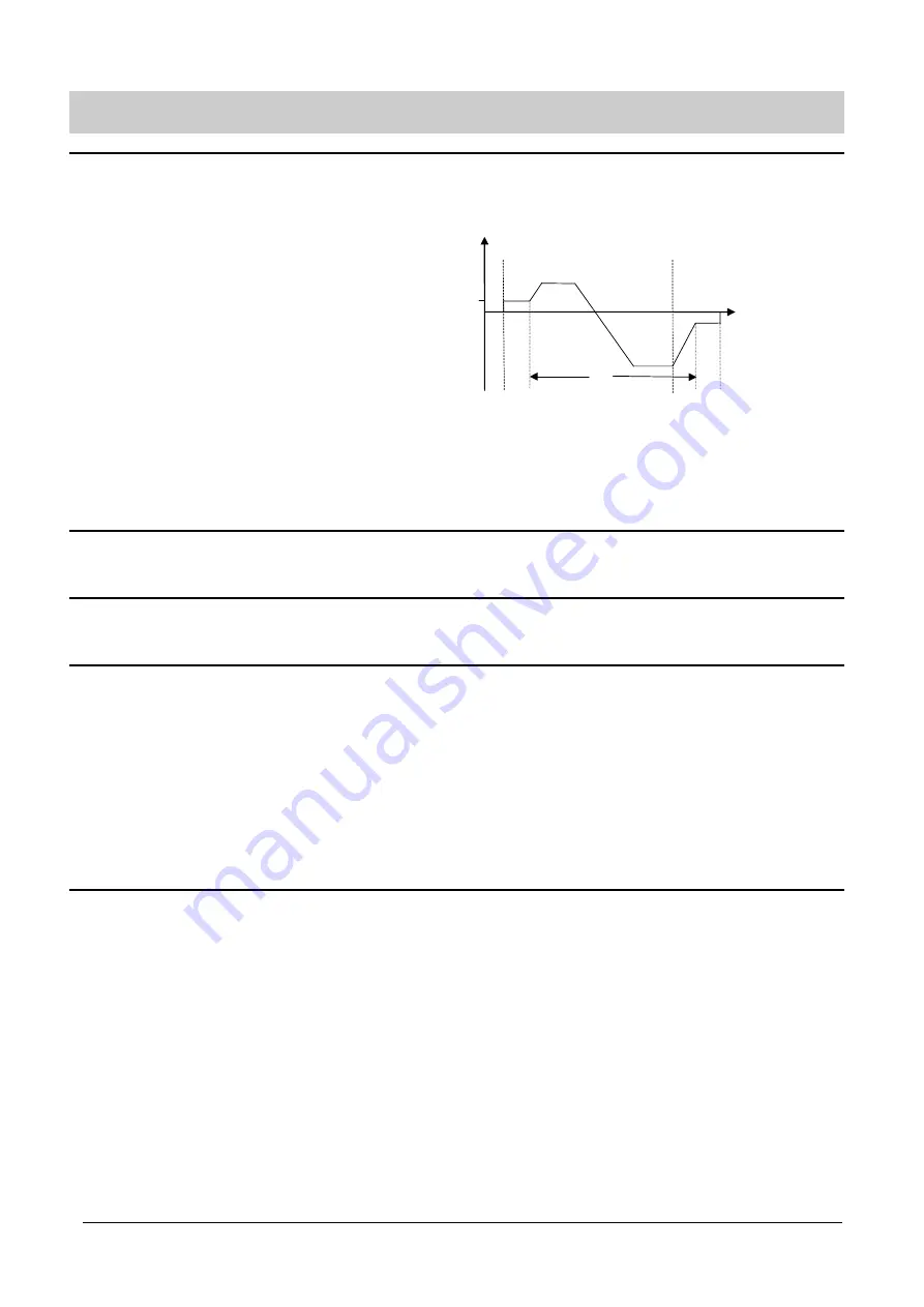
P064
External brake stopping time
(seconds)
0 - 20.0
[1.0]
As P063, only effective if the relay output is set to control an external
brake. This defines the period for which the inverter continues to run at
the minimum frequency after ramping down and while the external
brake is applied.
Notes:
(1)
Settings for P063 and P064 should be slightly longer
than the actual time taken for the external brake to
apply and release respectively.
(2)
Setting P063 or P064 to too high a value, especially
with P012 set to a high value, can cause an
overcurrent warning or trip as the inverter attempts to
move a locked motor shaft.
P065
Current threshold for relay (A)
0 - 99.9
[1.0]
This parameter is used when P061= 9. The relay switches on when the
motor current is greater than the value of P065 and switches off when
the current falls to 90% of the value of P065 (hysteresis).
P066
Compound braking
0 - 1
[1]
0
= Off
1
= On. Permits faster ramp-down times and enhances stopping
capability.
P073
••••
DC injection braking (%)
0 - 150
[0]
This stops the motor by applying a DC current. This causes heat to be
generated in the motor rather than the inverter and holds the shaft
stationary until the end of the braking period. Braking is effective for the
period of time set by P003.
The DC brake can be activated using DIN1 - DIN3
(braking is active for
as long as the DIN is high - see P051 - P053)
.
WARNING: Frequent use of long periods of dc injection braking
can cause the motor to overheat.
If DC injection braking is enabled via a digital input
then DC current is applied for as long as the digital
input is high. This causes heat in the motor.
ON
OFF
t
P063
A
t
P064
A
f
f
mi
B
t
A = Brake applied
B = Brake removed


