10/39
Smart Infrastructure
LMV6 Installation Guide
CC1J7560en
3 Description of the terminals
4/21/2020
3 Description of the terminals
Note!
AGG9 connector sets!
The AGG9 connectors of the connecting cables for the LMV6 may only be removed or
replaced when the plant is shut down (all-pole disconnection)!
Key
Terminal
Terminal markings on LMV6 housing
Coding
Plug-in space coding
Type (ASN)
Product designation for 200 packaging units
Pin
Connection pin number
Input Input
terminals
Output Output
terminals
Function Function
description
Current
Maximum permissible current rating (refer to
Technical Data
)
Parameter
Parameter number impacting the function or behavior of the inputs/outputs
3.1 LMV6
3.1.1 Terminal X11, X12
X11/X12
1 2 3 4 1 2 3 4
X
11
X
12
/0
11
9
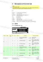
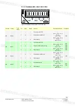
Figure 4: Description of terminal X11 / X12
Terminal Coding
Type
(ASN)
Pin
Input
Output
Function
Electrical limit value
X11
---
1
---
●
DC power supply for system
components
24 V DC
Approx. 24 V DC
Max. 1.25 A
2
---
●
Communication signal
CAN_H
DC U
↔
5 V, Rw = 120
Ω
,
Level according to ISO-DIS
11898
3
---
●
Communication signal
CAN_L
DC U
↔
5 V, Rw = 120
Ω
,
Level according to ISO-DIS
11898
4
---
●
Signal reference
GND
---
X12
---
1
---
●
DC power supply for system
components
24 V DC
Approx. 24 V DC
Max. 1.25 A
2
---
●
Communication signal
CAN_H
DC U
↔
5 V, Rw = 120
Ω
,
Level according to ISO-DIS
11898
3
---
●
Communication signal
CAN_L
DC U
↔
5 V, Rw = 120
Ω
,
Level according to ISO-DIS
11898
4
---
●
Signal reference
GND
---

