38/39
Smart Infrastructure
LMV6 Installation Guide
CC1J7560en
13 List of figures
4/21/2020
13 List of figures
Figure 1: LMV60.110A2 connection assignment ............................................................ 7
Figure 2: LMV6 protection classes .................................................................................. 8
Figure 3: AGG6.200 protection classes .......................................................................... 9
Figure 4: Description of terminal X11 / X12 .................................................................. 10
Figure 5: Description of terminals X51 / X52 ................................................................ 11
Figure 6: Description of terminal X61 / X62 / X63 / X64 ............................................... 12
Figure 7: Description of terminal X71 / X72 / X73 ......................................................... 13
Figure 8: Description of terminal X81 / X82 / X83 / X84 ............................................... 14
Figure 9: Description of terminal X91 / X92 / X93 ......................................................... 15
Figure 10: Description of terminal X13 .......................................................................... 17
Figure 11: Description of terminal X161 ........................................................................ 17
Figure 12: Block diagram inputs / outputs ..................................................................... 18
Figure 13: AZL66 connection assignment .................................................................... 19
Figure 14: SQM4 connection assignment ..................................................................... 19
Figure 15: AGG6.200A5 connection assignment .......................................................... 20
Figure 16: Connection of the protective earth (PE) / functional earth (FE) with the
mounting plate ....................................................................................................... 22
Figure 17: AGG6.500 shielding mechanism (optional) ................................................. 22
Figure 18: Earthing and wiring of the LMV6 .................................................................. 24
Figure 19: TN
−
S earthing .............................................................................................. 27
Figure 20: TT earthing .................................................................................................. 27
Figure 21: Protective earth (PE), functional earth (FE) ................................................. 28
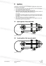
Figure 22: 2-pole ignition .............................................................................................. 29
Figure 23: 1-pole ignition .............................................................................................. 29
Figure 24: 1-pole ignition with low impedance at the burner housing ........................... 30
Figure 25: 1-pole ignition with high impedance of the burner housing .......................... 31
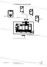
Figure 26: Example for wiring, earthing and shielding of the LMV6 .............................. 33
Figure 27: Installation of all components in the burner: CAN bus cable LMV6
last
SQM4 < 20 m ......................................................................................................... 34
Figure 28: AGG6.641 .................................................................................................... 35
Figure 29: AGG6.635 .................................................................................................... 35
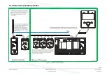
Figure 30: Parallel operation ......................................................................................... 36
Figure 31: Variant for parallel operation ........................................................................ 37

