P/N 315-049103-6
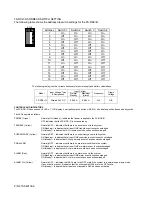
FS-RD2/-R ADDRESS SWITCH SETTING
The following table shows the address dip switch settings for the FS-RD2/-R.
Address
Switch 1
Switch 2
Switch 3
Switch 4
1 On On On On
2 Off On On On
3 On Off On On
4 Off Off On On
5 On On Off On
6 Off On Off On
7 On Off Off On
8 Off Off Off On
9 On On On Off
10 Off On On Off
11 On Off On Off
12 Off Off On Off
13 On On Off Off
14 Off On Off Off
15 On Off Off Off
16 Off Off Off Off
The following table gives the currents necessary for power supply and battery calculations.
Input Current
Model
Input Voltage Type
& Designation
Normal
Standby
Maximum
(Alarm)
Frequency
Ripple
Voltage
FS-RD2/-R
Filtered 24 V DC
0.048 A
0.085 A
N/A
N/A
CONTROLS AND INDICATORS
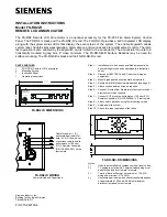
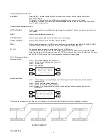
The FS-RD2/-R has a sounder, 6 LEDs, 1 LCD display, 4 navigational push buttons (M1-M4), 4 dedicated push buttons and a keyswitch.
The LEDs operate as follows:
POWER (Green)
Normally ON (steady) – indicates that power is applied to the FS-RD2/-R.
OFF indicates that the FS-RD2/-R is not powered up.
TROUBLE (Yellow)
Normally OFF – indicates that there is no trouble event in the system.
ON (flashing) – indicates that at least ONE trouble event is unacknowledged.
ON (steady) – indicates that ALL trouble events have been acknowledged.
SUPERVISORY (Yellow)
Normally OFF – indicates that there is no supervisory event in the system.
ON (flashing) – indicates that at least ONE supervisory event is unacknowledged.
ON (steady) – indicates that ALL supervisory events have been acknowledged.
PRE-ALARM
Normally OFF – indicates that there is no pre-alarm condition in the system.
ON (flashing) – indicates that at least ONE pre-alarm event is unacknowledged.
ON (steady) – indicates that ALL pre-alarm events have been acknowledged.
ALARM (Red)
Normally OFF – indicates that there is no alarm event in the system.
ON (flashing) – indicates that at least ONE alarm event is unacknowledged.
ON (steady) – indicates that ALL alarm events have been acknowledged.
ALARM SIL (Yellow)
Normally OFF – indicates that NACs are in the OFF state if the system is in normal supervisory mode.
If any event is present, it indicates that the silenceable NACs are in the OFF state.
ON (steady) – indicates that at least one silenceable NAC has been activated.
SW-9
OFF ON
1
2
3
4
Summary of Contents for FS-RD2
Page 4: ...P N 315 049103 6 ...


