FS-100 Installation & Operation Manual
P/N 315-699461
29
RS485 COMMUNICATIONS CIRCUIT
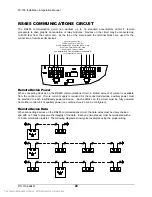
The RS485 communication circuit can address up to 16 standard annunciators and/or 8 remote
processors to drive graphic annunciation or relay modules. Devices on the circuit may be connected up
to 4000 feet from the control unit. At the top of the main board the terminal blocks are used for the
connection of remote serial devices.
Remote Device Power
When connecting devices on the RS485 communications circuit, a limited amount of current is available
from the control unit. If more current supply is required for the connected devices, auxiliary power must
be provided to each insufficiently powered device. Each address on the circuit must be fully powered
from either control unit or auxiliary power (
no combined source can be configured
).
Remote Device Data
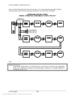
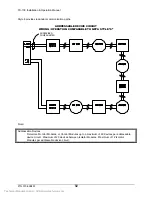
When connecting devices on the RS485 communications circuit, the data wires must be daisy chained
and with no T-taps to preserve the integrity of the data. Each end (two places) must be terminated with a
120 ohm termination resistor. The following diagrams show typical examples using the proper wiring.
Serial Interface Circuit
24VDC nominal, 0.4A max.
Wire Resistance-25 ohms/line (4000’ max)
Wire Type-Twisted Pair for data
Supervised, Power Limited
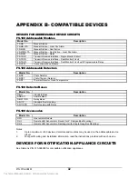
See Installation & Operation Manual Appendix D
for Compatible Devices
Technical Manuals Online! - http://www.tech-man.com

