background image

FS-100 Installation & Operation Manual


P/N 315-699461 

8

GENERAL DESIGN FEATURES 

Environmental 

All hardware is suitable for use in an interior or protected location. 

Power Limiting 

The AC power and battery wiring are not power limited.  All other circuits leaving the control unit are 
power limited, provided the proper installation rules are maintained. 

Ground Fault Detection 

The control unit provides ground fault detection and a ground fault will trigger the common fault buzzer 
and system trouble LED. 

Transient Protection 

Transient protection devices are provided where needed to meet the requirements of UL864.   

Security Functions 

Processor control and addressing allow inclusion of several functions to assure security of the system. 

Multi-level password protection of programming functions prevents unauthorized configuration changes. 

Device type supervision: If the type reported by an addressable sensor or module, does not agree with 
the configuration, the system reports a trouble. 

Device address supervision: The system checks that all configured devices on the addressable device 
circuit and the RS485 circuit responds to an address poll.  If a configured device is missing, the system 
reports a trouble.  The system also polls unused addresses periodically.  If a device responds to such a 
poll of a non-configured device, the system reports a trouble.  Two devices addressed the same also 
cause a trouble to be reported. 

REGULATORY STANDARDS 

The FS-100 control unit meets the requirements of industry and government regulatory agencies as 
noted. 

Federal Communications Commission 

The FS-DACT  meets the requirements of the Code of Federal Regulations (CFR 47), Part 68, for 
connection of equipment to the public switched telephone network. 

Underwriters Laboratories 

The FS-100 Fire Alarm control unit is listed under UL Standard 864 for compliance to NFPA Standard 72 
for fire service 

Technical Manuals Online! - http://www.tech-man.com

Summary of Contents for FireSeeker FS-100

Page 1: ...Ltd 8 Fernwood Road 2 Kenview Boulevard Florham Park NJ 07932 Brampton Ontario L6T 5E4 CN P N315 699461 1 447290 Fire Safety FireSeeker Fire Alarm Control Panel Model FS 100 Installation Operation and Maintenance Manual Technical Manuals Online http www tech man com ...

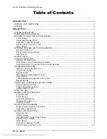
Page 2: ... 5 ADDRESSABLE DEVICES 5 Siemens Addressable Detectors 5 Variable Thresholds 5 Operator Alerts 6 Other Siemens Addressable Devices 6 Heat Detectors 6 Addressable Modules Monitor and Control 6 Manual Stations 6 PROCESSOR CONTROLLED OUTPUT ZONES 6 Output Sounding Patterns 6 Control of Audible Silencing 6 Audible Silence Inhibit 6 EVENT HISTORY 7 GENERAL DESIGN FEATURES 8 Environmental 8 Power Limiti...

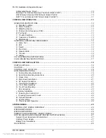
Page 3: ...NSTRUCTIONS 17 CONTROL UNIT INSTALLATION 18 PARTS SUPPLIED 18 CAUTION 18 CONTROL UNIT LOCATION 18 ENCLOSURE MOUNTING 18 A Surface Mounting Instructions 19 B Semi Flush Mounting Instructions 20 C Knock Outs 21 D Main Board Installation 21 E AC Supply Connection 21 F Transformer Installation 22 G Front Plate Assembly 22 H Front Plate Mounting 22 I Door Assembly 23 J Battery Installation 23 K Powerin...

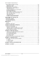
Page 4: ... KEYPAD PROGRAMMING 35 PROGRAMMING SECURITY 35 MAINTENANCE 36 GENERAL 36 QUICK TEST WALK TEST 37 APPENDIX A REFERENCE INFORMATION 38 WIRE SELECTION GUIDES 38 Resistance of Solid Copper Wire 38 Notification Appliance Circuit Wire Selection Guide 38 Addressable Device Circuit Wire Selection Guide 39 BATTERY SIZE CALCULATIONS 40 APPENDIX B COMPATIBLE DEVICES 42 DEVICES FOR ADDRESSABLE DEVICE CIRCUITS...

Page 5: ...or performance at least two 2 times a year or more often if local requirements dictate Fire alarm control units cannot last forever Even though this control unit was made to last for the expected life of the fire alarm system any part could fail at any time Therefore a regular test program should be followed and documented to make sure that each part of the system is tested as in Chapter 7 of NFPA...

Page 6: ...evices should be used to install and maintain a functioning fire alarm signaling system NFPA 70 National Electrical Code NFPA 72 National Fire Alarm Code NFPA 101 Life Safety Code For other standards that may apply contact the authority having jurisdiction For NFPA publications contact National Fire Protection Association Batterymarch Park Quincy Massachusetts 02269 Technical Manuals Online http w...

Page 7: ...e signaling and indicating interfaces and connection of the main system power supply Optional boards mount on the main board The display board mounts on the front plate allowing it to carry the controls and displays which must be accessible All normal operation is controlled from the front of the control unit via push button switches Displays are provided by an 80 character alphanumeric backlit LC...

Page 8: ...tem coder capable of zone coded operation All of the NACs are power limited and can be wired for Class A Style Z or Class B Style Y operation RS485 Communications Circuit The FS 100 control unit has an RS 485 Communications Circuit that will drive up to 16 remote LCD annunciators and 8 Serial Relay Units and Serial Annunciator Units on the RS485 communication line Status Relays Three dry relay con...

Page 9: ...orm C contacts The control unit can address up to 8 FS RU Serial Relay Units and or FS SAU Serial Annunciator Units Auxiliary power supplies will be required to power units beyond the control unit capability Serial Annunciator Unit and Serial Annunciator Extender The Siemens FS SAU includes a processor board and an annunciator driver board The processor board receives commands from the control uni...

Page 10: ...ially hardware circuits the fact that the outputs are commanded and controlled by the processor does provide more versatility than in a total hardware system All functional selections are included in the control unit programming process Output Sounding Patterns The notification appliance circuits are operable in different sounding patterns Any circuit is selectable to any of eight software generat...

Page 11: ...witch activation Alarm silence manual and automatic System reset Power up Entry to Programmer Mode Secondary configuration edited Validity check on backup configuration Errors detected or no errors detected Running of comparison function Same or different Replacement of primary configuration Execution of Auto program Exit from Programmer Mode System time or date change Input point disable enable S...

Page 12: ...If the type reported by an addressable sensor or module does not agree with the configuration the system reports a trouble Device address supervision The system checks that all configured devices on the addressable device circuit and the RS485 circuit responds to an address poll If a configured device is missing the system reports a trouble The system also polls unused addresses periodically If a ...

Page 13: ...puts Current 0 5 amp maximum available for auxiliary power outputs RS485 circuit and option boards 0 4 amp maximum per power output Non Resettable Power Outputs Power limited Voltage 24 VDC nominal Ripple 1 5 VAC maximum Resettable Power Output Power limited Voltage 24 VDC nominal Ripple 1 5 VAC maximum Status Relays Includes alarm supervisory and trouble relays Contact Rating 1 A 28 VDC maximum r...

Page 14: ... by control unit for grounded circuit Voltage 24 VDC nominal Current 0 020A maximum normal or trouble Current 0 025A maximum shorted Ripple 1 5 VAC maximum CT Reverse Polarity Programmable for Trouble or Supervisory or either operation Power limited Supervised by receiver for short or open circuit Supervised by control unit for grounded circuit Voltage 24 VDC nominal Current 0 020A maximum normal ...

Page 15: ...tallation Operation Manual P N 315 699461 11 DACT Circuit Optional DACT Board Model FS DACT Power limited Supervised for short or open circuit Maximum Voltage 60 VDC Technical Manuals Online http www tech man com ...

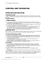
Page 16: ... point programmed for PAS including two stage manual stations activates the Alarm LED display and buzzer pulsing but delays all other outputs system and user for 15 seconds b Operation of the ACKNOWLEDGE button within 15 seconds will add 165 seconds to the timer value to make the total delay 180 seconds c If an ALARM SILENCE button is pressed or the sensor returns to a normal reading before the ex...

Page 17: ...rammed for trouble acknowledge required when the indicated trouble condition has been cleared the system will revert to standby condition after the ACKNOWLEDGE button is pressed Note Some trouble conditions require a system reset to restore the control unit D Supervisory Condition Supervisory conditions are indicated similar to regular system trouble conditions except that when a supervisory condi...

Page 18: ...rill signal C Recall To signal recall after a drill proceed as follows 1 Press MENU 2 At the next screen select More 3 Select RECALL 6 At the next screen select Yes 4 Operate ALARM SILENCE to terminate recall signal D Pre Alarm 1 A pre alarm condition is annunciated by Pre alarm LEDs and buzzers on the control unit and RS485 LCD Annunciators and RS485 Remote Processors The LEDs flash and buzzers a...

Page 19: ...rwrite old when filled b Printer if used records all events c For more information see the event history section 2 Access to history To recall past events proceed as follows a Press MENU button b Operate button identified as More c Operate button identified as More d Operate button identified as View History e Operate upper left button for previous event display f Operate lower left button for nex...

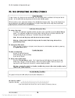
Page 20: ...arm silence inhibit if set prevents the alarm from being silenced for a predetermined time To reset panel after alarm When the alarm condition is corrected return the panel to normal standby operation by pressing the System Reset switch Trouble Operation Trouble is indicated by System Trouble LED flashes LCD will display trouble conditions Panel buzzer sounds To silence the trouble buzzer Press th...

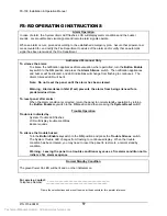
Page 21: ...t if set prevents the alarm from being silenced for a predetermined time To reset panel after alarm When the alarm condition is corrected return the panel to normal standby operation by turning the Button Enable keyswitch to the ON position and then pressing the System Reset switch Trouble Operation Trouble is indicated by System Trouble LED flashes LCD will display trouble conditions Buzzer sound...

Page 22: ...ctrical conduit Installation is to be done only by qualified personnel who have thoroughly read and understood these instructions CAUTION It is recommended that the printed circuit boards be removed for any procedure that may cause dust metal shavings grease or any such matter that may affect the circuit boards and or parts There may be several sources of power into the control unit Each source mu...

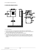
Page 23: ...screw type and length must support the control unit options and battery set Note You may need a different screw type depending on the wall material 3 Any auxiliary power supply or battery enclosure may be mounted immediately below the main enclosure close nipple allowing a minimum of 1 inch in between the enclosures for clearance between the doors Keeping the wire run to the control unit short wil...

Page 24: ... material 3 The back box can be mounted up to 3 1 2 inches into the wall Place the semi flush trim around the back box and affix to the wall with four 10 x 3 4 inch wood screws provided with trim Note You may need a different screw type depending on the wall material 4 Any auxiliary Power Supply or battery enclosure may be mounted immediately above or below the main enclosure close nipple allowing...

Page 25: ...ly to terminal block TB2 on the main board The supply should originate from a separate fused circuit It should be provided with a breaker or other means of isolation 2 Observe the wiring order the bottom terminal is ground and must be wired back to the electrical panel ground earth bonding point or another good ground acceptable to the authority having jurisdiction and the electrical inspector The...

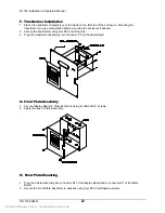
Page 26: ... using four 6 32 locking nuts 3 Plug the transformer assembly into connector P5 on the Main Board G Front Plate Assembly 1 Secure Display Board to Plate Assembly using ten 6 32x1 4 screws 2 Apply Overlay to Plate Assembly H Front Plate Mounting 1 Plug the Cable Assembly into connector P4 of the Display Board and to connector P1 of the Main Board 2 Secure the Front Plate Assembly to backbox using f...

Page 27: ...attery sets 55 AH and smaller The FS 100 battery charging circuitry can only support systems requiring up to 38 AH battery sets The control unit uses a 24V battery set Connect the two 12V batteries or four 6V batteries in series with 12 AWG wire minimum Route the battery leads to the left of the enclosure and up to the battery termination block TB5 The battery leads are not power limited Observe p...

Page 28: ...efore connecting the field wiring check the wiring for opens shorts grounds and stray voltages Warning Damage may result if a high voltage insulation tester is used on wiring while connected to the control unit Terminate the field wiring to the main board in accordance with the diagrams in Section V and the system design documents NOTE All wiring must be in accordance with local codes and the Nati...

Page 29: ...included below Devices that may be satisfactorily used with the control unit are shown in the compatible device listing in Appendix B Wire reference data are included in Appendix A CONTROL UNIT WIRING OVERVIEW The overall arrangement of boards in the control unit is shown in the following diagram 2 3 1 1 Main Board 2 FS DACT board or FS MT board Note When using FS DACT the FS 232 cannot be used 3 ...

Page 30: ...nd side of the board Route all high voltage and non power limited wiring together and away from power limited wiring 24V Battery Set 7 to 38AH Supervised Non Power Limited 120VAC 60Hz 1 3A max Supervised Non Power Limited AC N GND Keep All Non Power Limited Wiring Separate from Power Limited Wiring 2 3 1 E C A B G F A Non power limited High Voltage AC power or B B Non power limited High Voltage AC...

Page 31: ... 030 FS RU RE8 Serial Relay Unit 0 030 FS SAU SAE16 Serial Annun Unit 0 030 Total must not exceed 0 75 Amps Auxiliary Power Supply Connect a UL Listed auxiliary supply when the power requirement calculation indicates that an additional source is required Battery Size Calculations For calculation of battery size requirements see appendix A ALARM TROUBLE SUPERVISORY R Status Relay Contacts Shown in ...

Page 32: ...Style Y Class B Supervised Power Limited See P N315 096363 for Compatible Devices Notification Appliance Circuit Style Z Class A Supervised Power Limited See P N 315 096363 for Compatible Devices 24K 1 2W Polarity shown in activated condition See Typical Wiring above See Typical Wiring above NAC Rating Alarm Voltage 24VDC nominal Max Alarm Current 1 5A Max Ripple 16VAC Max Wire Voltage Drop 1 0VDC...

Page 33: ...he connected devices auxiliary power must be provided to each insufficiently powered device Each address on the circuit must be fully powered from either control unit or auxiliary power no combined source can be configured Remote Device Data When connecting devices on the RS485 communications circuit the data wires must be daisy chained and with no T taps to preserve the integrity of the data Each...

Page 34: ...ns for UL Listed compatible addressable devices are indicated below Refer also to the instruction sheets packed with each device Detectors and modules may be wired together according to several NFPA defined wiring styles The wiring style that is appropriate for your installation should be determined from the relevant building codes and the Authority Having Jurisdiction Addressable Device Circuit S...

Page 35: ...interrogation ADDRESSABLE DEVICE CIRCUIT WIRING OPERATION COMPARABLE TO NFPA STYLE 4 Note Addressable Devices Detectors Monitor Modules or Control Modules up to a maximum of 60 devices per addressable device circuit Maximum of 20 devices per Isolator Module Maximum of 12 Isolator Modules per addressable device circuit SUPERVISED POWER LIMITED TO OPTIONAL BRANCH ES OF LOOP CIRCUIT Technical Manuals...

Page 36: ...TION COMPARABLE TO NFPA STYLE 6 Note Addressable Devices Detectors Monitor Modules or Control Modules up to a maximum of 60 devices per addressable device circuit Maximum of 20 devices between Isolator Modules Maximum of 12 Isolator Modules per addressable device circuit SUPERVISED POWER LIMITED Technical Manuals Online http www tech man com ...

Page 37: ...The ADBX 11 provides means to obtain a local audible alarm at the specific detector location The integral horn on the ADBX 11 will sound when either the detector installed in the base has latched into the alarm state or when criteria developed through logic programming is met It will remain on until the detector is successfully reset or the logic criteria are no longer met A separate 24VDC power s...

Page 38: ...ield connections The FS TRI M s small size and light weight design allows it to be installed inside a single gang box or behind a device being monitored without being rigidly mounted The FS TRI D monitor module is similar to the FS TRI S except that it provides two Style B initiating circuits for normally opened dry contact fire alarm and supervisory tamper devices The FS TRI D uses two consecutiv...

Page 39: ... style keypad mounts on the front panel within the cabinet The keypad may also be easily removed if desired See the Siemens Programmer s Manual P N 315 699490 for detailed information of system programming PROGRAMMING SECURITY The following levels of security protect the system from unauthorized use User Locked Door Maintenance Locked Door and 4 digit Maint Password Technician Locked Door and 5 di...

Page 40: ...st cycle enter the 4 digit maintenance password into the control unit or LCD annunciator When the menu is displayed select Auto test and press the associated switch The Auto test cycle will be completed and the control unit returns to normal Results will be displayed on the display anomalies only or the printer full data according to the selected mode The system will automatically monitor drift of...

Page 41: ...configurable length of time Quick test terminates automatically into normal standby mode using a timer The value of the timer is configurable The timer can be configured to limit the total time of the quick test i e the timer is started only when quick test is entered or to limit the time between device activation s i e the timer is re started after each activation Alarm activation s that occur in...

Page 42: ...fication Appliance Circuit must not have a voltage drop greater than 1 volt The following chart is based on the following premises The entire load is at the end of the wire run worst case Resistance is of solid copper wire Contact your local distributor or the factory if further information is needed in your circumstances Maximum Wire Loop Distance Feet Signal Load A 18 AWG 16 AWG 14 AWG 12 AWG 0 ...

Page 43: ...nce cable High velocity of propagation cable 60 minimum Each loop runs separate from all other circuits Run out and out separately from in and in Different models or types of cable should not be in the same loop Maximum Wire Loop Distance Feet Includes all branches of a Style 4 loop Wire size 18AWG 16AWG 14AWG 12AWG Wire length 6150 9750 10 000 10 000 Cable length 3075 4875 5 000 5 000 The termina...

Page 44: ...y Alarm 0 030 X NA FS RU Serial Standby 0 010 X NA Relay Unit Alarm 0 170 X NA FS RE16 Serial Standby 0 000 X NA Relay Extender Alarm 0 160 X NA FS SAU Serial Standby 0 015 X NA Annunciator Unit Alarm note 4 0 040 X NA FS SAE16 Serial Standby 0 005 X NA Annunciator Ext Alarm note 4 0 000 X NA Addressable Devices Catalog Quantity X Current A Standby X NA Alarm X NA Standby X NA Alarm X NA Standby X...

Page 45: ...ischarge rate in alarm Battery capacity decreases with age 2 The Standby current Alarm current must never exceed 3 0 Amps 3 The following states the maximum standby current allowed using a 38 AH battery set 60 hours of standby time is 0 5 Amps 24 hours of standby time is 1 2 Amps 4 Does not include lamp or LED current add separately 5 When using the FS MT Municipal Tie Module add the following cur...

Page 46: ... Detector FS DPT Photo Thermal Detector FS DT Thermal Detector Fixed Temperature FS 100 Detector Bases Model No Description DB 11 Standard Base ADBX 11 Audible Base DB X11RS Relay Base AD 11P Standard Duct Housing AD 11XPR Duct Housing with Relay FS 100 Accessories Model No Description LIM 1 Line Isolator Module RLI 1 Remote LED Annunciator Round for 4 Octagon Box Mounting RLI 2 Remote LED Annunci...

Page 47: ...ross zone CZ2B Cross zone DETECTOR General alarm HEAT Thermal sensor LCDxx LCD Annunciator xx MAIN Main panel MANL PULL Manual pull station Mntc Detector maintenance alert PAS Positive alarm sequence PAS INHBT PAS inhibit switch PHOTO Photoelectric sensor PRE SIGNL pre signal PreA Pre alarm SUPERVSRY Supervisory SUPR Supervisory TRBL Trouble TROUBLE Trouble USERx User defined input x WATERFLOW Wat...

Page 48: ...ble ADD00 Addr 00 Device on the loop responded to address 00 ADDaa Not Pgmd Device responding is not programmed on loop address aa ADDaa NoRespons Device not responding ADDaa Mult Add Resp More than one device responding on the loop at address aa ADDaa Com Trb Device responses are not valid on the loop address aa ADDaa Inc Dev ID Device responding is not the type programmed on the loop address aa ...

Page 49: ...a Enabled MAIN or LCDxx shown on bottom line NACxx Active Confirm NAC activation confirmed Panel Reset MAIN LCDxx shown on bottom line Power Up PriConfigCopied Primary configuration copied to backup QuickTest Exit Exited Quick Test MAIN or LCDxx shown on bottom line QuickTest Start Started Quick Test MAIN or LCDxx shown on bottom line SN1aa AV CtrClr AV counter for sensor SN1aa cleared SN1aa AV Ct...

Page 50: ...N FS MTMunicipalTieModule 315 699462 FS 232 RS232 Board 315 699463 FS DACT Serial Digital Communicator 315 699464 FS RD Remote LCD Annunciator 315 699465 FS RU Serial Relay Unit 315 699466 FS RE8 Serial Relay Extender FS SAU Serial Annunciator Unit 315 699468 FS SAE16 Serial Annunciator Extender FS AE Fire Alarm Accessory Enclosure 315 699470 Technical Manuals Online http www tech man com ...

Reviews:

Related manuals for FireSeeker FS-100