background image

A6V11712824_----_a

3

en

Installation

Intended use

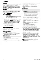
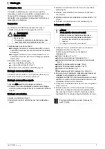
The module can use the output for control purposes and

the input to monitor the status of a potential-free contact.

A housing is available to protect the module from

environmental influences and to raise the protection

category.

Preparation

The installation procedure depends on the module's place

of use and type of installation.

WARNING

Electrical voltage
Electric shock

·

During installation work, voltage must not be

applied to the cables.

1.

Define the place of use.

Installation outside an electric cabinet or control panel

(module always in FDCH221 housing)

Installation in electric cabinet or in control panel (any

type of module installation)

2.

Define the type of installation.

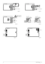
on a plane surface (Fig. 1)

on a top hat rail (Fig. 2)

in FDCH221 housing (Fig. 3)

Installation on a plane surface

1.

Position the module on a plane surface (Fig. 1).

2.

Use two screws to secure the module.

Installation on a top hat rail

1.

Fix two installation feet to the module.

2.

Press the module and the installation feet against the

top hat rail until the feet snap in (Fig. 2).

Installation in housing

1.

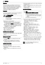
Open the housing (Fig. 6).

2.

Determine the cable entries in the housing and break

these open.

3.

Use two screws to fit the housing on a plane surface

(Fig. 4).

4.

Secure the M20 cable glands on the housing and guide

in the cables (Fig. 5).

5.

Use two M3 x 12 screws to fit the module in the housing

(Fig. 3).

6.

Close the housing with the screws provided (Fig. 6).

Electric connection

NOTICE

Incorrect polarity and reliability of contact
Module defect or line interrupt

·

When connecting up the detector line, note the

positive and negative connections.

·

Connect only one wire to each terminal.

1.

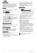
Connect the cables to the terminals as shown in the

connection diagram (Figs. 13 and 14).

Refer to the following figures for connection details:

Detector line: Fig. 12

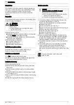
Input monitored for open line: Fig. 7

Input monitored for open line and short circuit: Fig. 8

'Normal operation' output: Fig. 9

'Inverted operation' output: Fig. 10

Output not monitored: Fig. 11

DC 24 V supply: Fig. 9/Fig. 10

2.

If you are using shielded cables for the detector line,

connect the shielding to the DBZ1190-AB connection

terminal. The shielding must not touch any extrinsic

earthing potentials or metal parts in the housing.

3.

Connect the resistors to the end of the input line (Fig. 7

and Fig. 8).

4.

Connect the jumper to J1/J2 depending on how the

output is being used and connect the additional

components as shown in Fig. 9, Fig. 10 or Fig. 11.

Be sure to connect the resistor (Fig. 9) at the end of the

line.

For more information, refer to document

A6V11712780.

Summary of Contents for FDCI361

Page 1: ...äuse fr Interface d entrées Interface d entrées sorties Boîtier es Módulo de entrada Módulo de entrada salida Carcasa it Modulo ingressi digitali Modulo in out digitali Contenitore en Installation de Montage fr Montage es Montaje it Montaggio Fig 1 Fig 2 Fig 3 Fig 4 Fig 5 Fig 6 FDCI361 FDCIO361 3 3 kW IN1 IN1 3 3 kW 680 W FDCI361 FDCIO361 IN1 IN1 Fig 7 Fig 8 ...

Page 2: ...1 J2 OUT A 1 2 3 4 DC 24 V external Fig 9 Fig 10 Max DC 30 V Max AC 22 V 2 AT not used FDCIO361 OUT A 1 2 3 4 J1 COM NO NC not used LINE LINE LINE LINE LINE LINE FDCI361 FDCIO361 FDCI361 FDCIO361 LINE Fig 11 Fig 12 LINE LINE LINE FDCI361 LINE LINE LINE FDCIO361 OUT A J2 J1 Fig 13 Fig 14 ...

Page 3: ...ese open 3 Use two screws to fit the housing on a plane surface Fig 4 4 Secure the M20 cable glands on the housing and guide in the cables Fig 5 5 Use two M3 x 12 screws to fit the module in the housing Fig 3 6 Close the housing with the screws provided Fig 6 Electric connection NOTICE Incorrect polarity and reliability of contact Module defect or line interrupt When connecting up the detector lin...

Page 4: ...das Gehäuse mit zwei Schrauben auf eine plane Fläche Fig 4 4 Befestigen Sie die Kabelverschraubungen M20 am Gehäuse und führen Sie die Kabel ein Fig 5 5 Montieren Sie den Baustein mit zwei Schrauben M3 x 12 im Gehäuse Fig 3 6 Schließen Sie das Gehäuse mit den mitgelieferten Schrauben Fig 6 Elektrischer Anschluss HINWEIS Falsche Polarität und Kontaktsicherheit Defekt des Bausteins oder Leitungsunte...

Page 5: ...z le boîtier Fig 6 2 Déterminez les entrées de câbles dans le boîtier et dégagez les 3 Montez le boîtier sur une surface plane avec deux vis Fig 4 4 Fixez les presse étoupe M20 sur le boîtier et introduisez les câbles Fig 5 5 Montez le module d interface dans le boîtier avec deux vis M3 x 12 Fig 3 6 Fermez le boîtier avec les deux vis fournies lors de la livraison Fig 6 Raccordement électrique AVI...

Page 6: ... una superficie plana Fig 4 4 Sujete los prensaestopas para cable M20 en la carcasa e introduzca los cables Fig 5 5 Monte el módulo con dos tornillos M3 x 12 en la carcasa Fig 3 6 Cierre la carcasa con los tornillos suministrados Fig 6 Conexión eléctrica AVISO Polaridad incorrecta y seguridad de contacto Defecto del módulo o circuito abierto del cable Observe las conexiones positivas y negativas d...

Page 7: ...trata dei cavi nel contenitore e aprirli 3 Montare il contenitore con due viti su una superficie piana Fig 4 4 Fissare i pressatavi M20 al contenitore e introdurre i cavi Fig 5 5 Montare il modulo nel contenitore con due viti M3 x 12 Fig 3 6 Chiudere il contenitore con le viti accluse Fig 6 Collegamento elettrico AVVISO Errata polarità e sicurezza di contatto Difetto del modulo o interruzione dell...

Page 8: ...ntrées sorties es Módulo de entrada salida it Modulo in out digitali FDCH221 S54312 F3 A1 en Housing de Gehäuse fr Boîtier es Carcasa it Contenitore FDCM291 A5Q00003855 en Mounting foot de Montagefuss fr Pied de montage es Pie de montaje it Piedino di montaggio A5Q00004478 en Metal cable gland M20 x 1 5 de Metall Kabelverschraubung M20 x 1 5 fr Presse étoupe métallique M20 x 1 5 es Prensaestopas m...

Reviews: