background image

2
Smart Infrastructure

A6V13605540_en--_b

Smart Infrastructure

2022-10-14

Functions

The goal of the Connect Box is to radically lower the effort, investment, and complexity
involved to integrate devices to a common system and retrofit additional functionality to
optimize the building.

Plug-and-play installation by installers such as electricians

Library of over 500 field devices ready to connect

Smart converter of 11 communication protocols, both standard and proprietary, wired
and radio

Default data retrieval at 10-minutes intervals (excluding IoT-sensors that have their own
frequencies to minimize battery consumption). Commands (downlink) are sent instantly.

Local or cloud connectivity via 4G IP, field bus

Over-the-air updates via 4G

Local IoT private network based on LoRa

Powerful integration up to third-party applications

Full-service, no networking skills required thanks to 4G cloud connectivity

BMS essentials included in the user console on 

connectbox.siemens.com

Public API management and documentation

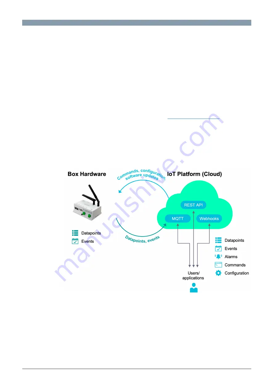
The offering consists of a hardware component - the Connect Box - and a software
component, either the cloud license or the on-premise license. Depending on the customer
use case, the appropriate software component needs to be selected. Both versions use the
IoT Platform in the back-end and the user console as a central interface to activate, manage,
and configure the device.

With the Connect Box cloud license, data can either be sent to a server by API Restful or
MQTT (connection with LAN or 4G, SIM card is provided and pre-mounted), or be converted
locally to BACnet IP or Modbus IP. Configuration, pairing of equipment, and selection of
properties are done remotely on our web platform (console of configuration). Functionalities
such as graphs, alarms, and synoptics are included in the box license. The 4G SIM card
subscription is also included in the license.

Summary of Contents for Connect Box

Page 1: ...ssible for all If the building already has a BMS the device connects to the main bus as the third party If there is no BMS a BMS network is directly created by the device Telemetry and controls Collects data and controls equipment Smart converter Unifies various field communication protocols on one device Web connected Automatically connects to the cloud via 3G 4G or ethernet cable Powerful IoT de...

Page 2: ...ll service no networking skills required thanks to 4G cloud connectivity BMS essentials included in the user console on connectbox siemens com Public API management and documentation The offering consists of a hardware component the Connect Box and a software component either the cloud license or the on premise license Depending on the customer use case the appropriate software component needs to ...

Page 3: ...t Box CWG L3 IOT P55695 L100 A200 3 years cloud license IoT for Connect Box CWG L3 S P55695 L100 A210 3 years cloud license Small for Connect Box CWG L3 M P55695 L100 A220 3 years cloud license Medium for Connect Box CWG L3 L P55695 L100 A230 3 years cloud license Large for Connect Box CWG L3 SAT P55695 L100 A240 3 years cloud license Satellite for Connect Box CWG L3 ADD2 P55695 L100 A260 3 years ...

Page 4: ...nna e g EAD WMO86916 Technical documentation of equipment Technical documentation of IoT sensors Diagram of the communication network s of the BMS The optional hardware cannot be ordered through Siemens Technical and mechanical design 3 GSM antenna 4 LoRaWAN antenna 5 Plug in terminal block with screw terminals RS485 1 RS485 2 Modbus RTU 6 USB micro port used for maintenance only 7 Plug in termina...

Page 5: ...unication to subsystem Ethernet 1 2 Green Continuously ON Continuously ON Link activ No connection KNX Green Continuously ON Continuously OFF Communication No communication to subsystem Power supply Green Continuously ON Connected power supply is compatible Red Continuously ON Connected power supply is not compatible To avoid damage change the power supply Product documentation Related documents s...

Page 6: ...void any risk of injury caused by a fall Where children are likely to be present In an outdoor locations Installation WARNING Electric shock Incorrect installation of the device may lead to electric shock injuries when touching the device Install the device in a lockable cabinet or use terminal covers Do not install the device in locations where children are likely to be present Conductors with a ...

Page 7: ... 100Base TX IEEE 802 3 compatible Bit rate 10 100 Mbps autosensing Protocol BACnet IP on UDP IP BACnet SC on TCP IP and HTTPS on TCP IP Cabling in house cabling only cable type 10 Mbps Min CAT3 shielded cable is recommended 100 Mbps Min CAT5 shielded cable is recommended Cable length Max 100 m 330 ft Modbus RTU interface Interface type EIA 485 not isolated Baud rate 300 600 1200 2400 4800 9600 192...

Page 8: ...LTE FDD B1 3 4 5 7 8 12 13 18 19 20 26 38 40 41 23dBm Rx sensitivity 110dBm 698 960MHz 1 0 5 0dBi 1710 2690MHz 1 0 3 8dBi Antenna type Omnidirectional rubber antenna with SMA connector Typical impedance 50 Ohm KNX interface Type KNX S and LTE mode Baud rate 9600 bauds Cabling in house cabling only 2 wire cable 0 75 mm2 AWG20 or 1 mm2 AWG18 With external supply Internal bus power Sink max 50 mA USB...

Page 9: ...Hz 917 2 MHz 917 4 MHz 917 6 MHz 917 8 MHz 918 0 MHz 918 2 MHz Downlink 923 3 MHz Europe EU_863_870 All SF5 to SF12 Uplink 868 10 MHz 868 30 MHz 868 50 MHz 867 10 MHz 867 30 MHz 867 50 MHz 867 70 MHz 867 90 MHz Downlink 869 525 MHz Europe EU_433 All SF5 to SF12 Uplink 433 175 MHz 433 375 MHz 433 575 MHz Downlink 434 665 MHz India IN_865_870 All SF5 to SF12 Uplink 865 0625 MHz 865 4025 MHz 865 985 ...

Page 10: ...peration as per IEC EN 60721 3 3 Class 1K22 2K12 Temperature 20 85 C 4 185 F Class 3K23 Operation in enclosed dry locations having no temperature or humidity control Temperature 0 40 C 32 104 F Mechanical ambient conditions Transport per IEC EN 60721 3 2 Operation as per IEC EN 60721 3 3 Class 2M4 Class 3M11 Standards directives and approvals Product standards IEC EN 62368 1 Information Technology...

Page 11: ...ing two conditions 1 This device may not cause harmful interference and 2 this device must accept any interference received including interference that may cause undesired operation FCC Caution Changes or modifications not expressly approved by Siemens Switzerland Ltd could void user authority to operate the equipment United States representative https new siemens com us en products buildingtechno...

Page 12: ... limits set forth for an uncontrolled environment This equipment should be installed and operated with minimum distance 20 cm between the radiator and your body The LoRaWAN antenna delivered by Siemens meets the FCC IC regulations If the installer makes the choice to use another antenna the maximum antenna gain allowed is 5 8 dBi to comply with FCC IC regulations limiting both maximum RF output po...

Page 13: ... 50 Ohm typical impedance Maximum antenna gain see table below Frequency band Antenna gain dBi GSM850 1 GSM1900 6 GPRS850 4TS 1 GPRS1900 4TS 6 WCDMA Band2 10 WCDMA Band4 9 WCDMA Band5 7 LTE Band2 10 LTE Band4 11 LTE Band5 7 LTE Band7 10 LTE Band12 6 LTE Band13 6 LTE Band25 10 LTE Band26 8 LTE Band41 9 LTE Band66 9 LoRaWAN antenna characteristics Gain 5 8 dB Housing Color Grey Dimensions per DIN 43...

Page 14: ...terface KNX KNX interface Power 12 24 VDC power input Dimensions All dimensions in mm and inches Issued by Siemens Switzerland Ltd Smart Infrastructure Global Headquarters Theilerstrasse 1a CH 6300 Zug 41 58 724 2424 www siemens com buildingtechnologies Siemens Switzerland Ltd 2022 Technical specifications and availability subject to change without notice Document ID A6V13605540_en _b Edition 2022...

Reviews: