background image

8 / 26 


Siemens 

HMI-LED 

CB1P3946en 

Building Technologies 

HMI-LED overview 

2013-08-19 

2.4  Communication protocol and interface 

The HMI-LED is connected to T-HI (RJ45) interface of Climatix 

POL

 400/600 

controller via standard network cable. The HMI-LED is set as Modbus master, and 
the Climatix 

POL

 400/600 controller is set as Modbus slave. 

The connection diagram is illustrated as below: 


The connection interfaces of HMI-LED are shown as below: 


The communication protocol is Modbus RTU with RS485 connector. 

The default protocol is as follows: 

Baud rate 

9600 

Parity 

Data bits 

Stop bits 

 
Define the Climatix controller T-HI port as Modbus slave in SCOPE, and configure 
the “target” member “ModbusOverservice” as “Active”. 


Connection diagram 

Interfaces


Communication 
protocol 

Communication 
settings 

Summary of Contents for Climatix HMI-LED POL831.25/STD

Page 1: ...Climatix HMI LED POL831 25 STD Basic Documentation CB1P3946en 2013 08 19 Building Technologies ...

Page 2: ...Technologies 2013 08 19 Siemens Switzerland Ltd Building Technologies Group International Headquarters Gubelstrasse 22 CH 6301 Zug Tel 41 41 724 24 24 Fax 41 41 724 35 22 www siemens com sbt 2012 2013 Siemens Switzerland Ltd Subject to change ...

Page 3: ...m list page 10 3 3 Page transition 10 3 3 1 Default page transition 10 3 3 2 Parameter list page or alarm history page transition 11 3 4 Present value list page 11 3 5 Parameter list page 12 3 6 Alarm list page 12 3 7 Alarm history page 13 4 HMI LED Programming 14 4 1 Basics 14 4 1 1 Initialization of Modbus communication 14 4 1 2 Register assignment 14 4 2 Hot key configuration 15 4 2 1 Unit ON O...

Page 4: ...ons The Climatix HMI LED product can only be operated by personnel who have been instructed by Siemens Building Technologies or their delegates and whose attention has been drawn to potential risks When wiring the system high voltage section must be strictly segregated from the AC 24 V safety extra low voltage SELV section in order to ensure protection against electric shock hazard Always observe ...

Page 5: ...2 SELV Safety Extra Low Voltage UINT Unsigned Integer Name Explanation Climatix Controller family with common tools SAPRO SAPRO programming tool SCOPE SCOPE commissioning and service tool 1 3 Purpose and scope This document provides information regarding the Climatix HMI LED device including the functions and operations The target readers of this document are technical personnel of Siemens OEM cus...

Page 6: ...sub page To get value from the present value list or parameter list To confirm the modification of parameter list or the password input Key SET Press and hold To switch to the parameter list page and alarm history page Press To switch among digit position in parameter configuration page Key ESC Press and hold To exit to upper level menu To exit from the parameter list page To cancel the modificati...

Page 7: ...r represented Lowercase letter displayed on LED Lowercase letter represented A a B b C c D d E e F f G g H h I i J j L l N n O o P p Q q R r S s T t U u V v Y y Z z 2 3 Local connection The local connection is a peer to peer connection between the HMI LED and one controller Climatix POL 400 600 controller The HMI LED provides a female RJ45 plug for standard net cable Display example on HMI LED scr...

Page 8: ...400 600 controller is set as Modbus slave The connection diagram is illustrated as below The connection interfaces of HMI LED are shown as below The communication protocol is Modbus RTU with RS485 connector The default protocol is as follows Baud rate 9600 Parity N Data bits 8 Stop bits 2 Define the Climatix controller T HI port as Modbus slave in SCOPE and configure the target member ModbusOverse...

Page 9: ...eters according to the current password level refer to Section 3 4 If the parameter list value cannot be displayed at the current password level users need to input the password of higher levels The alarm list page only shows the latest alarm with alarm code 3 2 Default pages The HMI LED provides the following three default pages which could be displayed automatically under certain circumstances O...

Page 10: ...in 5 minutes 3 2 3 Alarm list page When an alarm occurs the alarm list page will be displayed automatically to show the alarm information Only the latest alarm could be displayed on this page When a new alarm occurs the new alarm code will replace the old one which will be moved to the alarm history page 3 3 Page transition 3 3 1 Default page transition Select the value from the present value list...

Page 11: ...figuration page and the alarm history page Press key UP DOWN on the parameter configuration page to change the value The workflow is as follows 3 4 Present value list page The predefined values will be displayed alternately if there is no operation within 5 minutes The first 5 present values in the value list can be displayed on the screen alternately The number of scrolled values can be defined M...

Page 12: ...ct the parameter list page will be displayed as below Press key UP DOWN to scroll the parameter list on the screen Then press key SET to configure the selected parameter Press and hold key ESC to exit from the parameter list page and it will redirect to the present value list page 3 6 Alarm list page The alarm list page will be displayed automatically to show the latest alarm when an alarm occurs ...

Page 13: ...arm history page If there is no history alarm AL will be displayed as below Press key UP DOWN to switch among the history alarm pages The maximum number of history alarms in record is 32 If the number of history alarms reaches the upper limit the new alarm will be recorded and the earliest alarm will be removed from the history list Press and hold key SET ESC on the alarm history page to clear the...

Page 14: ...egister assignment The object or variable in SAPRO must be assigned to the register Only the Input register and Holding register are supported in the HMI LED according to the Modbus register list refer to Chapter 5 Appendix Modbus register list There are two ways to assign the register self define global variable recommend and mapping Using mapping method users need to define the corresponding aut...

Page 15: ...en to corresponding Holding register Further corresponding actions should be completed in SAPRO 4 2 1 Unit ON OFF Press key SET UP to write value 1 to the Holding register 137 Then a 2 second pulse will be created to support the carrying out ON OFF action with one key The application example of Unit ON OFF is shown as below 4 2 2 Alarm Acknowledgement When an alarm occurs press key SET DOWN to ack...

Page 16: ...pulse is created 4 3 Display value configuration The following displayed values need to be assigned to the input register according to the Modbus register list refer to Chapter 5 Appendix Modbus register list 4 3 1 Temperature display The engineering unit of temperature displayed on the HMI LED screen is C For example for controller B1 which connects to NTC sensor there is a temperature variable a...

Page 17: ...xact engineering unit and factional digital the Input register should be defined in SAPRO For example if the Input register 1 is defined as Boole variable then the VL_In needs to be converted from Boole to REAL and the VL_Unit should be configured as 0 as well as the VL_Factional Later the value will be transferred to the Input register 1 and the configuration will be written to the Input register...

Page 18: ... with this setpoint the 4 bit UINT should be set as 2002 The parameter quantity can be defined in SAPRO by configuring the Input register 136 as below 4 5 Alarm management The current alarm is displayed as alarm code on the HMI LED screen with the latest occurred and highest level as its highest priority The HMI LED provides 16 alarm codes with 16 levels and AL01 is the highest level For dismissed...

Page 19: ...ing Technologies HMI LED Programming 2013 08 19 Current alarms are saved to the Input register 101 History alarms are saved to the Input register 102 133 This part is programmed in the application example Current alarms History alarms Note ...

Page 20: ...vel password the HMI LED can visit the Holding registers 1 60 The service level password is stored in the Holding register 60 With factory level password the HMI LED can visit the Holding registers 1 100 The factory level password is stored in the Holding register 100 The data type of password is string so its function block is different from the normal parameter reading via AccessDB The Holding r...

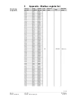
Page 21: ... VL14 30014 VL15 VL15 30015 VL16 VL16 30016 VL17 VL17 30017 VL18 VL18 30018 VL19 VL19 30019 VL20 VL20 30020 VL21 VL21 30021 VL22 VL22 30022 VL23 VL23 30023 VL24 VL24 30024 VL25 VL25 30025 VL26 VL26 30026 VL27 VL27 30027 VL28 VL28 30028 VL29 VL29 30029 VL30 VL30 30030 VL31 VL31 30031 VL32 VL32 30032 VL33 VL33 30033 VL34 VL34 30034 VL35 VL35 30035 VL36 VL36 30036 VL37 VL37 30037 VL38 VL38 30038 VL39...

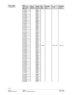
Page 22: ...VL14 30064 CFG VL15 30065 CFG VL16 30066 CFG VL17 30067 CFG VL18 30068 CFG VL19 30069 CFG VL20 30070 CFG VL21 30071 CFG VL22 30072 CFG VL23 30073 CFG VL24 30074 CFG VL25 30075 CFG VL26 30076 CFG VL27 30077 CFG VL28 30078 CFG VL29 30079 CFG VL30 30080 CFG VL31 30081 CFG VL32 30082 CFG VL33 30083 CFG VL34 30084 CFG VL35 30085 CFG VL36 30086 CFG VL37 30087 CFG VL38 30088 CFG VL39 30089 CFG VL40 30090...

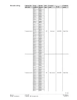
Page 23: ...40015 PL16 40016 PL17 40017 PL18 40018 PL19 40019 PL20 40020 PL21 40021 PL22 40022 PL23 40023 PL24 40024 PL25 40025 PL26 40026 PL27 40027 PL28 40028 PL29 40029 Password level 1 PL30 40030 INT User Level 999 9999 Read Write PL31 40031 PL32 40032 PL33 40033 PL34 40034 PL35 40035 PL36 40036 PL37 40037 PL38 40038 PL39 40039 PL40 40040 PL41 40041 PL42 40042 PL43 40043 PL44 40044 PL45 40045 PL46 40046 P...

Page 24: ...9 Read Write PL61 40061 PL62 40062 PL63 40063 PL64 40064 PL65 40065 PL66 40066 PL67 40067 PL68 40068 PL69 40069 PL70 40070 PL71 40071 PL72 40072 PL73 40073 PL74 40074 PL75 40075 PL76 40076 PL77 40077 PL78 40078 PL79 40079 PL80 40080 PL81 40081 PL82 40082 PL83 40083 PL84 40084 PL85 40085 PL86 40086 PL87 40087 PL88 40088 PL89 40089 PL90 40090 PL91 40091 PL92 40092 PL93 40093 PL94 40094 PL95 40095 PL...

Page 25: ...6 30101 HL01 30102 HL02 30103 HL03 30104 HL04 30105 HL05 30106 HL06 30107 HL07 30108 HL08 30109 HL09 30110 HL10 30111 HL11 30112 HL12 30113 HL13 30114 HL14 30115 HL15 30116 HL16 30117 HL17 30118 HL18 30119 HL19 30120 HL20 30121 HL21 30122 HL22 30123 HL23 30124 HL24 30125 HL25 30126 HL26 30127 HL27 30128 HL28 30129 HL29 30130 HL30 30131 HL31 30132 HL32 ALXX 30133 WORD Read only Alarm information ...

Page 26: ... Technologies 2013 08 19 Siemens Switzerland Ltd Building Technologies Group International Headquarters Gubelstrasse 22 CH 6301 Zug Tel 41 41 724 24 24 Fax 41 41 724 35 22 www siemens com sbt 2012 2013 Siemens Switzerland Ltd Subject to change ...

Reviews: