background image

Appendix 


A.2 Ordering data 


ASM 456 interface module 

60


Operating Instructions, 07/2015, J31069-D0162-U001-A6-7618 

Connectors 

M12 connectors can be obtained from the relevant specialist dealers (e.g. Binder). 

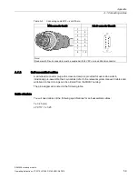
Table A- 4 

Pin assignment 

M12 connector (male) 

Pin 

Signal 

Core color 


+24 V 

Note data sheet 

provided by cable 

manufacturer 

RxD 

0 V 

RxD 

TxD 

TxD 

Free 

PE / shield 

A.2


Ordering data 

Table A- 5 

Ordering data - ASM 456 


Article number 

ASM 456 communications module  

for PROFIBUS DP V1 max. 2 readers can be connected 

6GT2002-0ED00 

ECOFAST terminal block 

6ES7194-3AA00-0AA0 

M12, 7/8" terminal block 

6ES7194-3AA00-0BA0 

Labels  

20 x 7 mm (pack of 340) 

3RT1900-1SB20 


Table A- 6 

Ordering data - accessories for ECOFAST connection 


Article number 

PROFIBUS ECOFAST hybrid plug 180 (pack of 5) 


with pin insert 


with socket insert 


6GK1905-0CA00 


6GK1905-0CB00 

PROFIBUS ECOFAST termination plug with terminating resistor 

6GK1905-0DA10 

ECOFAST hybrid cable (pre-assembled) 

6XV1830-7Bxxx * 

ECOFAST hybrid cable (not pre-assembled, sold by the meter) 

6XV1830-7AH10 

 *) These cables are available in different lengths. See Catalog IK PI for more details. 


Summary of Contents for ASM 456

Page 1: ...______________ ___________________ ___________________ ___________________ SIMATIC Ident RFID systems ASM 456 interface module Operating Instructions 07 2015 J31069 D0162 U001 A6 7618 Introduction 1 Description 2 Installation 3 Connection 4 Parameterization 5 Diagnostics 6 Firmware update 7 Technical specifications 8 Dimensional drawings 9 Appendix A ...

Page 2: ...ion may be operated only by personnel qualified for the specific task in accordance with the relevant documentation in particular its warning notices and safety instructions Qualified personnel are those who based on their training and experience are capable of identifying risks and avoiding potential hazards when working with these products systems Proper use of Siemens products Note the followin...

Page 3: ...tion of PROFIBUS DP and supply voltage 30 4 5 Connecting an ASM 456 up to functional earth 31 5 Parameterization 33 5 1 Hardware configuration 33 5 2 Parameter setting by means of GSD file 35 5 3 Parameter assignment with FB 45 55 and FC 56 36 5 3 1 Input parameters for ASM 456 36 5 3 2 Table of commands for ASM 456 38 5 4 Parameter assignment with the Ident profile and FB 101 116 132 40 5 4 1 Inp...

Page 4: ... interface module 4 Operating Instructions 07 2015 J31069 D0162 U001 A6 7618 A Appendix 57 A 1 Connecting cables 57 A 1 1 Routing of standard cables 57 A 1 2 Self assembled cables 59 A 2 Ordering data 60 A 3 Service Support 62 ...

Page 5: ... addition to these operating instructions you require the operating instructions for the DP master used You will find information on programming the module and a complete description of errors faults in the descriptions of the blocks FB 45 56 or FC 56 and in the function manual Ident profile and Ident blocks The manuals of the relevant product family contain information on the readers and code rea...

Page 6: ...the hardware of the interface module ASM 456 They comprise introductory chapters and reference chapters e g technical data The operating instructions include the following subject areas Connecting the interface module ASM 456 Parameterizing the interface module ASM 456 Diagnostics information Display elements of interface module ASM 456 Description of the firmware update Technical data and dimensi...

Page 7: ...e 2 1 Interface module ASM 456 with ECOFAST or M12 7 8 terminal block When operating the interface module with a SIMATIC S7 convenient function blocks are available to the user The following RFID systems and code reader systems can be operated with the ASM 456 RF200 normal addressing RF300 normal addressing filehandler RF600 RF620R RF630R RF680R RF685R MOBY D MOBY E MOBY I normal addressing fileha...

Page 8: ...dler is also implemented on ASM 456 The file handler is a file administration system similar to DOS for the Ident system MOBY I U and RF300 It consists of one program which is executed on the interface module For the SIMATIC application FC 56 and the RFID standard profile S7 are available Other features Degree of protection IP67 System integration with ECOFAST or M12 7 8 concept T functionality th...

Page 9: ...5 J31069 D0162 U001 A6 7618 9 Design The ASM has a terminal block for connecting up to the PROFIBUS DP which is available as an option and the ECOFAST version or M12 7 8 The following figure shows the basic design of the ASM 456 Figure 2 2 Basic design of the ASM 456 ...

Page 10: ... The following figure shows how the ASM 456 is integrated in an automation system Figure 2 4 Sample configuration ASM 456 The ASM 456 is linked into STEP 7 by means of a GSD file The ASM can then be configured using HW Config of the SIMATIC Manager the device configuration of the TIA Portal or another PROFIBUS tool e g operating mode You will find the GSD file on the DVD RFID Systems Software Docu...

Page 11: ...restrictions regarding the mounting position of the ASM 456 Mounting and clearance dimensions The following table shows the installation dimensions and clearance distances Table 3 1 Mounting dimensions Dimensions Mounting width 60 mm Mounting height 210 mm Mounting depth with ECOFAST terminal block 60 mm without connector with terminal block M12 7 8 54 mm without connector ...

Page 12: ...owing table shows the screws suitable for installing the I O modules Table 3 2 Screw types Screw type Description M5 cylinder head screw according to ISO 1207 ISO 1580 DIN 84 DIN 85 The minimum screw length must be 20 mm You also need a set of DIN 125 washers Cylindrical head screw with M5 hexagon socket according to DIN 912 Tools required Medium sized cross head screwdriver or 8 mm socket wrench ...

Page 13: ...irements The base unit is already mounted Tools required Recessed head screwdriver medium size Installing the terminal block 1 Fit the terminal block onto the base unit 2 Screw the terminal block onto the base unit torque 1 to 1 3 Nm Tighten the screws already in the terminal block uniformly Figure 3 1 Plug the terminal block onto the base unit and screw it tight Note Degree of protection IP65 IP6...

Page 14: ... block You will find the labels in the base unit when it is supplied 8 labels on the base unit 1 label on the terminal block Requirements You can order replacement labels For order numbers refer to the appendix Tools required 2 5 to 4 mm screwdriver Replacing labels 1 Push the screwdriver into the small opening of the label at an angle then lever it out Figure 3 2 Removing labels 2 Push the label ...

Page 15: ...M 456 is wired up and operational Follow the steps below to remove the ASM 1 Switch off the supply voltage for the ASM 456 2 Disconnect the wiring from the terminal block 3 Undo the 4 securing screws of the terminal block 4 Remove the terminal block from the basic device 5 Disconnect the wiring on the basic device 6 Remove the securing screws from the basic device ...

Page 16: ...Installation 3 5 Removing the ASM 456 ASM 456 interface module 16 Operating Instructions 07 2015 J31069 D0162 U001 A6 7618 ...

Page 17: ...upport industry siemens com cs ww en view 35222591 You will find information on setting up a PROFIBUS network with STEP 7 in the manual PROFIBUS with STEP 7 https support industry siemens com cs ww en view 59193579 Reader connector system One reader always occupies one M12 connector socket X1 X2 on the ASM 456 A pre assembled cable therefore permits the optimum and simple connection of the reader ...

Page 18: ...een communications module Reader M12 connector eight pin socket 160 mohm m depending on the current consumption may lead to a voltage drop on the reader This voltage drop can mean that the required minimum voltage on the reader is below the required 20 V Cable lengths 20 m 6GT2891 4FN50 are not permitted for the RF680R RF685R readers 4 1 Setting the PROFIBUS address Properties With the PROFIBUS ad...

Page 19: ...onnection block M12 7 8 Permitted PROFIBUS DP addresses are 1 to 99 1 Remove the two seal caps from the rotary switches if necessary use a 14 mm socket wrench 2 Set the required PROFIBUS address on the rotary switches using a screwdriver Lower rotary switch 1st position Upper rotary switch 10th position 3 Screw the two seal caps back onto the rotary switches torque 0 5 to 0 8 Nm Figure 4 2 Setting...

Page 20: ...onfiguration plug s screw connection 2 Loosen the screw connection of the cap on the configuration connector and pull it off 3 Set the PROFIBUS address with the DIL switches Figure 4 4 Setting the PROFIBUS address on the configuration plug 4 Screw the cover cap back down plug the configuration plug onto the connection block and screw the configuration plug to the connection block 5 After starting ...

Page 21: ...t be terminated with the terminating resistor Requirements You have set the PROFIBUS address according to your project Required tools Screwdriver stripping and crimping tool for wiring the ECOFAST connector plug if you are not using pre assembled ECOFAST connector plugs Accessories required Pre assembled ECOFAST hybrid cable with ECOFAST connector The cable is available in different lengths If you...

Page 22: ... ECOFAST connector plugs Pin Assignment View of ECOFAST connector plug wiring end for supply and loop through connec tion A PROFIBUS DP signal A B PROFIBUS DP signal B 1 Electronics encoder supply 1L voltage supply for ASM 456 and write read device 2 Ground for electronic encoder supply 1M 3 Load voltage ground 2M 4 Load voltage supply 2L unused on ASM 456 You will find the assembly instructions i...

Page 23: ...down the interlock for ECOFAST connector plugs on the connection block 2 Connect the ECOFAST connector plugs for 1L and the PROFIBUS DP into the sockets on the connection block In so doing note the mechanical coding of the connector plugs for supply and loop through connection 3 Press up the interlock for ECOFAST connector plugs Figure 4 5 Connecting up ECOFAST connector plugs ...

Page 24: ...corresponding ECOFAST connection module For procedure refer to connecting up ECOFAST connector plugs For order number refer to Ordering data section Figure 4 6 Connecting the ECOFAST terminating resistor Note The terminating resistor is supplied by the electronic encoder supply 1L Perfect functioning of the terminating resistor is only guaranteed if the electronics encoder supply 1L is within the ...

Page 25: ...Wire connection block M12 7 8 when the supply voltage is switched off The PROFIBUS address is set according to your configuration and the terminating resistor is switched on if required Tools required Stripping tool screwdriver for wiring the M12 or 7 8 connector if you are not using a pre assembled connector Required accessories Preassembled cables with connectors If you do not use preassembled c...

Page 26: ...ment for the M12 7 8 connector Table 4 2 Connection assignment for M12 connector PROFIBUS DP Pin Assignment View of M12 connector wiring side 1 Supply positive P5V2 2 Data line A RxD TxD N 3 Data reference potential M5V2 4 Data line B RxD TxD P 5 Shield Thread Shield Can only be used for the M12 terminating resistor Looping the voltage through to the next connector via a 5 core cable is not permit...

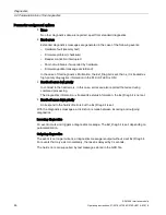
Page 27: ...s load voltage supply 2M 2 Chassis electronics sensor supply 1M 3 PE 4 Electronics encoder supply 1L voltage supply for ASM 456 and write read device 5 Load voltage supply 2L unused on ASM 456 Note When connecting up the supply voltage we recommend the cable specified in the Ordering data section cable 5 x 1 5 mm2 pre assembled with 7 8 connectors If you want to prepare the cable yourself you shou...

Page 28: ...D0162 U001 A6 7618 Connecting up M12 7 8 connector 1 Press the connector M12 or 7 8 into the relevant round socket on the connection block Make sure the connectors and sockets are properly interlocked tongue and groove 2 Use the knurled locking ring to secure the connector Figure 4 7 Connecting M12 7 8 connectors ...

Page 29: ...minate PROFIBUS DP with the M12 terminating resistor For the order number refer to the section Ordering data 1 Plug the M12 terminating resistor into the right hand M12 circular socket connector Loop through on the terminal block Make sure the interlock has properly engaged 2 Use the knurled locking ring to secure the M12 terminating resistor Figure 4 8 Connecting the M12 terminating resistor Clos...

Page 30: ...ply and one socket for looping through the supply voltage and PROFIBUS DP The connector for supply and the socket for loop through connection are linked with one another internally Result If you remove the terminal block during operation other PROFIBUS nodes do not fail Figure 4 9 Loop through connection of PROFIBUS DP and supply voltage NOTICE Ensuring the degree of protection The IP65 IP66 or IP...

Page 31: ...rents and the cable cross sections required this may result in the cable isolation and contacts overheating and to the device being damaged 4 5 Connecting an ASM 456 up to functional earth Properties The ASM 456 needs to be connected to functional earth This normally happens automatically when you mount the device on a grounded metal support If you mount the module on a support that is not grounde...

Page 32: ...able with minimum cross section of 4 mm2 Cable lug Connecting the ASM 456 to functional earth Standard grounding via the securing screw Optional grounding via a grounding cable 1 Mount the module on the grounded metallic base Grounded metallic base Unpainted thread or surface of the nut 1 Isolate the grounding cable and secure the cable lug 2 Screw the cable lug on to the communication module M5 g...

Page 33: ...nfig of the SIMATIC Manager using the Options Install new GSD function The file is incorporated into the project view of the TIA Portal using the Options Manage device description file function You can incorporate the communications module in your project using the hardware catalog Figure 5 1 Network view in the TIA Portal Depending on the connected reader you need to use the appropriate module Wi...

Page 34: ...rtal You will find the file on the RFID Systems Software Documentation DVD in the folder daten PROFI_GSD ASM456 To allow the configuration software to use the full functionality diagnostics texts firmware update support of GSD revision 5 or higher is required The ASM 456 is displayed in the device configuration under Other field devices PROFIBUS DP Ident Systems SIEMENS AG MOBY ...

Page 35: ...ting the relevant parameters Parameter name Value Note User Mode Ident profile RFID standard profile Default FB 45 FC 45 FB 55 FC 55 FC 56 MOBY Mode RF200 RF300 RF600 MV4x0 MOBY U D Default RF680R RF685R MOBY I E normal addressing RF300 file handler MOBY U file handler only with FC 56 multitag or RFID standard profile MOBY I file handler Transmission speed 19 2 kBd 57 6 kBd 1 115 2 kBd Default 1 D...

Page 36: ... type SLG4x The VMDS memory size is 16KB The INIT command for the VMDS must be specified using 4000 hex 5 RF300 filehandler 11 0 scanning_time MOBY I B 16 00 FF A value not equal to 00 is only practical if parameters for MOBY_mode have been set accordingly MOBY D RF200 RF300 reserved 00 MOBY U B 16 00 C8 12 0 option_1 B 16 00 02 04 13 0 distance_limiting MOBY U normal transmit power B 16 05 0A 0F ...

Page 37: ...per ASM 8 0 MDS IO control B 16 0 1 4 5 Enable disable presence check 9 0 ECC_mode TRUE FALSE TRUE is only permitted when MOBY mode is set to 1 9 2 priority_RW TRUE FALSE 9 3 priority_RWD TRUE FALSE 10 0 MOBY mode B 16 1 4 5 6 MOBY I U 11 0 scanning_time MOBY I B 16 00 FF A value not equal to 00 is only of any use if MOBY_mode has been parameterized accordingly MOBY U B 16 00 C8 12 0 SLG_number B ...

Page 38: ...h normal addressing Command code Description available in the MOBY system normal chained 01 41 Write to transponder all 02 42 Read transponder read fixed code all 03 43 Initialize transponder RF300 RF620R RF630R MOBY U D 04 44 Reader status RF200 RF300 RF620R RF630R MOBY U D 08 48 Turn off transponder MOBY U 0A 4A Switch antenna on off RF200 RF300 RF620R RF630R MOBY U D 0B 4B Transponder status RF...

Page 39: ...ITE Write data in file W READ Read data from file R DELETE Delete file on transponder D MOBY I U RF300 filehandler ATTRIB Give file attribute Y COVER Protect transponder structure C MOBY I U RF300 filehandler DIR Read transponder directory G MOBY I U RF300 filehandler MDS STATUS Request transponder status F END Terminate communication with the transponder K MOBY U RF300 filehandler TRACE Absolute ...

Page 40: ...Parameter assignment with the Ident profile and FB 101 116 132 5 4 1 Input parameters for ASM 456 Note that the input parameters of the RFID standard profile differ from those of the Ident profile essentially due to the changed physical address setting of the reader Figure 5 3 Input parameters for ASM 456 with the Ident profile and RFID standard profile with FB 101 116 132 ...

Page 41: ... file WRITE 77 w Writes data to a file PHYSICAL READ 70 p Reads data from a transponder code reader system by specifying the physical start address the length and the password PHYSICAL WRITE 71 q Writes data to a transponder code reader system by specifying the physical start address the length and the password READER STATUS 74 t Reads out the status of the communications module reader TAG STATUS ...

Page 42: ... ASM 456 interface module 42 Operating Instructions 07 2015 J31069 D0162 U001 A6 7618 Command Command code Description HEX ASCII READ CONFIG 61 a Reads out the parameters from the communications mod ule reader WRITE CONFIG 78 x Sends new parameters to the communications module reader ...

Page 43: ...of the ASM 456 Table 6 1 Status LEDs for ASM 456 LEDs Meaning ON Lights up when there is logic voltage at the ASM is generated by the 24 V sup ply voltage DC 24 V Lights up when the 24 V supply voltage is connected to the ASM ACT_1 ACT_2 Lights up when the reader processes a user command no significance with RF200 RF300 RF600 MOBY D U ERR_1 ERR_2 1 A flashing pattern indicates the last error to oc...

Page 44: ...dling On ASM is in start up mode Connection to DP Master failed ASM not detecting a baud rate Check the PROFIBUS DP connec tion Check the DP Master Bus interrupt DP Master not functioning Check all cables on your PROFIBUS DP network Check whether the connector plugs for the PROFIBUS DP are securely plugged into the ASM flashes On The project data sent to the ASM by the DP Master do not match the c...

Page 45: ...rmware On Off 1 x flash every 3 s Off Off 1 x flash every 3 s Off ASM successfully ramped up waiting for reset command n x flash es m x flashes The last reported fault in the channel can be seen from the number of flash es n m On Flashing Rapid flashing Flashing Rapid flashing Firmware update alternate flashing of the error LEDs at approximately 1 Hz not relevant 6 2 Parameterization of the diagno...

Page 46: ...mation in the PLC SF LED is ON Hard soft errors low priority In contrast to the hard errors in this case errors are also reported that arise during command processing The diagnostics information is treated like status information the Ext_Diag bit is not set Hard soft errors high priority Correspond to the hard soft errors but the Ext_Diag bit is set With the diagnostics messages a distinction is m...

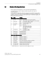
Page 47: ...luding header 7 status_type Bit 7 1b Identifier for status 0 alarm Bit 6 0 1d Type for status message 8 slot_number Bit 7 0 0d Device in total 9 specifier Bit 7 2 Reserved Bit 1 0 00b No further differentiation 10b Status inactive outgoing 01b Status active incoming 11b Reserved 10 channel_num Bit 7 0 1d Relating to reader 1 2d Relating to reader 2 11 function_num See Profile Guideline 12 error_de...

Page 48: ...Diagnostics 6 3 Structure of the diagnostics frame ASM 456 interface module 48 Operating Instructions 07 2015 J31069 D0162 U001 A6 7618 ...

Page 49: ...80R RF685R are connected to the ASM 456 the firmware update of the readers must be performed via the WBM of the readers You can start the WBM from the TIA Portal Requirements The ASM is connected to PROFIBUS with functional DP communication basic communication only no application required The firmware update can be made regardless of whether an application is running If the firmware update is perf...

Page 50: ...f the ASM during which the new firmware is activated active commands on the ASM are canceled If the option is not selected the ASM 456 continues to operate with the previous firmware version The new firmware is activated the next time the power supply is cycled While you download to the ASM this is indicated by alternate flashing of the ERR_1 and ERR_2 LEDs at approximately 1 Hz With the appropria...

Page 51: ...ption is selected a successful update is followed by a new startup of the ASM active commands on the ASM are canceled If the option is not selected the ASM 456 continues to operate with the previous firmware version The new firmware is activated the next time the power supply is cycled 7 Click the Run update button to start the update While you download to the ASM 456 this is indicated by alternat...

Page 52: ...Firmware update ASM 456 interface module 52 Operating Instructions 07 2015 J31069 D0162 U001 A6 7618 ...

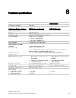
Page 53: ...s 8 pin Max cable length 1000 m reader dependent 2 m standard length for other standard cables and self assembled cables refer to the section Connecting cables Page 57 Connectable readers 2 x readers of the RFID families RF200 RF300 RF600 MOBY D U Software functions SIMATIC S7 function blocks FB 45 55 normal addressing with out multitag Ident profile RFID standard profile with FB 101 116 132 FC 56...

Page 54: ...All mounting positions are possible Weight Base unit M12 7 8 terminal block ECOFAST terminal block Approx 210 g Approx 235 g Approx 130 g Degree of protection IP67 Environmental conditions Temperature range during operation 0 55 C Temperature range during transporta tion and storage 40 70 C MTBF Mean Time Between Failures in years 122 years Approvals cULus File E116536 1 To allow this the relevant...

Page 55: ...le Operating Instructions 07 2015 J31069 D0162 U001 A6 7618 55 Dimensional drawings 9 The following figure shows the dimensional drawing of an ASM 456 with bus connection block Figure 9 1 Dimensional drawing of ASM 456 in mm ...

Page 56: ...Dimensional drawings ASM 456 interface module 56 Operating Instructions 07 2015 J31069 D0162 U001 A6 7618 ...

Page 57: ... of standard cables Figure A 1 M12 connecting cable reader Connecting cable MOBY E I U Length 2 m 5 m Figure A 2 Connecting cable extension cable M12 M12 RF200 RF300 RF600 connecting cable Extension cable for all RFID MOBY systems Length 2 m 5 m 10 m 20 m 50 m Figure A 3 Connecting cable M12 D sub Connecting cable MOBY D Length 2 m ...

Page 58: ...mption of the connected reader must however be taken into account You will find information in the relevant system manuals Sequential connection of more than 2 sub sections to form a long section of cable should be avoided due to the additional contact resistances Pin assignment Table A 1 M12 connecting cable reader M12 connector male Write read device connector female 1 2 2 5 3 3 4 4 5 6 6 1 7 8 ...

Page 59: ...d with 24 VDC via an additional connector A 1 2 Self assembled cables A write read connector plug with screw on clamps is provided for users who want to individually pre assemble their own cables refer to the relevant system manual Cables and write read connector plugs can be ordered from the MOBY catalog The pin assignment is listed in the following table Cable structure You will need cables of t...

Page 60: ...ns module for PROFIBUS DP V1 max 2 readers can be connected 6GT2002 0ED00 ECOFAST terminal block 6ES7194 3AA00 0AA0 M12 7 8 terminal block 6ES7194 3AA00 0BA0 Labels 20 x 7 mm pack of 340 3RT1900 1SB20 Table A 6 Ordering data accessories for ECOFAST connection Article number PROFIBUS ECOFAST hybrid plug 180 pack of 5 with pin insert with socket insert 6GK1905 0CA00 6GK1905 0CB00 PROFIBUS ECOFAST te...

Page 61: ...ug 7 8 for voltage 5 per pack with pin insert with socket insert 6GK1905 0FA00 6GK1905 0FB00 Covering caps 7 8 10 items 6ES7194 3JA00 0AA0 These cables are available in different lengths See Catalog IK PI for more details Table A 8 Ordering data RFID accessories Article number Reader cable MOBY I E U 2 m 6GT2091 4FH20 5 m 6GT2091 4FH50 MOBY D reader cable 2 m 6GT2691 4FH20 Reader cable RF200 RF300...

Page 62: ...Support for Process Industries and Drives On the Internet on the Support home page https support industry siemens com cs de en of Process Industries and Drives PD you will find various services There you will find the following information for example Our newsletter containing up to date information on your products Relevant documentation for your application which you can access via the search fu...

Page 63: ...iate courses to get you started Please contact your local training center or the central training center in D 90327 Nuremberg Phone 49 0 180 523 56 11 0 14 min from the German landline network deviating mobile communications prices are possible For information about courses see the SITRAIN homepage http sitrain automation siemens com sitrainworld ...

Page 64: ...Appendix A 3 Service Support ASM 456 interface module 64 Operating Instructions 07 2015 J31069 D0162 U001 A6 7618 ...

Reviews: