Diagnostics
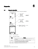
6.1 Diagnosis using LEDs
ASM 456 interface module
44
Operating Instructions, 07/2015, J31069-D0162-U001-A6-7618
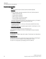
LEDs
Meaning
PRE_1, PRE_2
2)
RFID: Indicates the presence of a transponder.
MV: LED on - camera on and in stop mode
LED off - no connection to camera or error status on camera
LED flashes - a flashing pattern shows the value of "number_MDS".
RxD_1, RxD_2
Indicates live communication with the reader. May also indicate malfunctions on
the reader.
1)
The meaning of the individual flash patterns and the associated fault/error descriptions can be
found in the relevant FB and FC documentation.
2)
In multitag mode, this LED uses a flash interval to indicate the number of data carriers currently
within the range of influence of the reader.
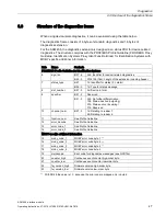
Table 6- 2
LED display for PROFIBUS diagnosis
BF
SF
Cause of error
Error handling
On
–
•
ASM is in start-up mode.
–
•
Connection to DP Master failed.
•
ASM not detecting a baud rate
•
Check the PROFIBUS DP connec-
tion.
•
Check the DP Master
•
Bus interrupt
•
DP Master not functioning
•
Check all cables on your
PROFIBUS DP network.
•
Check whether the connector plugs
for the PROFIBUS DP are securely
plugged into the ASM.
flashes
On
•
The project data sent to the ASM
by the DP Master do not match the
configuration of the ASM.
•
Check the project for the ASM
(input/output, PROFIBUS address).
•
Correct GSD file being used?
flashes
–
•
ASM has detected the baud rate,
but is not activated by the DP Mas-
ter.
•
ASM has not been assigned project
plans.
•
Check the PROFIBUS address set
in ASM and/or in the project soft-
ware.
•
Check the project for the ASM
(station type).
On
flashes
•
There is a hardware defect in the
ASM.
•
Replace the ASM.
Off
On
•
Diagnosis available
•
Evaluate the diagnostic information.
On
Off
•
The set PROFIBUS address is
incorrect or greater than 99.
•
Set the address in the range 1 to 99
and carry out new run-up.
– = Status not relevant


