AlgoPilot terminalB3Q661 / B3Q681 / B3Q686
Operating instructions
Building Technologies
Control Products and Systems
Page 1: ...AlgoPilot terminal B3Q661 B3Q681 B3Q686 Operating instructions Building Technologies Control Products and Systems ...
Page 2: ...in the subject thereof By acceptance of the document the recipient acknowledges these rights and under takes not to publish the document nor the subject thereof in full or in part nor to make them available to any third party without our prior express writ ten authorization nor to use it for any purpose other than for which it was delivered to him ...
Page 3: ...LOCKING OPERATION logging out 25 Switching ORGANIZATION to MANNED UNMANNED 26 Switching INDIVIDUAL ZONE OFF ON without time limit 28 Switching INDIVIDUAL ZONE OFF ON with time limit 30 Switching ALL ZONES in a SECTION OFF ON 32 Switching DETECTORS OFF ON 34 Service functions 36 Switching REMOTE TRANSMISSION OFF ON 36 Switching ALARM DEVICES OFF ON 38 Testing ALARMDEVICES 40 TEST CONDITION per SECT...
Page 4: ...perating elements 89 Standby display 90 Operating menus with softkeys 91 Menu types and properties 92 Menu navigation 94 Operator access and access rights 96 User category 96 Password 96 Authorization level 97 Starting operation 98 Logging in 99 Logging out 101 Logging in Logging out navigation overview 103 Message categories 104 Overview of message categories 104 Alarm buttons and displays 106 Al...
Page 5: ...cellaneous 125 Area Section Zone terminology 125 Manned and Unmanned operating mode 126 Timeouts 128 Function lists 4 129 FIRE ALARM SIGNAL operation 129 EXTINGUISHING operation 132 CONTROLS operation 134 Operation DEVICE 135 ALARMING 138 DIRECT ACCESS 139 SETTINGS 139 ...
Page 6: ...er This introductory page About this document Contains information about terms and abbrevi ations which are used in this document as well as information about the document ver sions Safety regulations Contains all the information you need to safely work with this system Operating instructions Œ Ž Specific instructions for working with this system This section contains descriptions of the steps nee...
Page 7: ...ns disclaims all liability for damage or injuries caused by the incor rect application of the instructions or disregard of warnings of danger contained in the documen tation This applies in particular to Personal injuries or damage caused by improper use and incorrect use Personal injuries or damage caused by disregarding safety instructions in the documentation or on the product Personal injuries...
Page 8: ...ification on site Check the product operability and release the product sys tem or device for use by the operator customer They are also responsible for trouble shooting They have had the training appropriate to his her func tion and to the products devices and systems to be commissioned and have at tended the technical train ing courses for commis sioning personnel Maintenance personnel They unde...
Page 9: ... as Operate or Full message are shown in bold The softkeys are selected by pressing the corresponding button to the left or right of a menu The wording inside the angle brackets indicates how they relate to the other buttons This helps to distinguish them from a display message LED displays The indicator lamps on the panel are known as LEDs Display The liquid crystal display LCD shows text message...
Page 10: ...ance may lead to the consequences indicated Classification Meaning Consequences DANGER Imminent danger à May cause danger to life or se rious bodily injury WARNING Dangerous situation à May cause serious bodily harm CAUTION May cause dangerous situations à May cause minor injuries NOTE Possibly harmful situation à May cause damage to the product or to objects in the immediate vicinity of the prod ...
Page 11: ...al voltage supply must be provided with a sign reading DANGER External voltage Mains leads to the control panel must be installed separately and provided with a clearly marked fuse Earthing must be carried out in compliance with local safety regulations When work is carried out in explosion hazardous areas the appropriate safety precautions must be taken Assembly in stallation com missioning and i...
Page 12: ...g Please re quest written approval from us and the relevant authorities concerning intended system modifica tions and system extensions Components and spare parts Locally procured components and spare parts must comply with the technical specifications laid down by the manufacturer This compliance is always ensured with original spare parts Only use fuses with the specified fuse characteristics Wr...
Page 13: ...s The document is primarily concerned with how something is done Brief step by step instructions are therefore provided for all actions Additional information F You will find more information which will provide a greater understanding of this fire detection system in chapter Basic system information from page 85 onwards Before getting started i For a better understanding of how to use these operat...
Page 14: ...a softkey may be labeled as follows Zone OFF when the corresponding zone is switched ON The labeling changes to Zone ON when the corresponding zone is switched OFF The softkey can also be used to call up a sub menu when mixed statuses arise At section level a softkey can have the following meaning for example All DETECTOR zones OFF when all zones are switched ON or All DETECTOR zones ON when all z...
Page 15: ...ctions of other nodes 2 Then select the function for switching off this zone Search methods There are three different ways of going to a specific node Searching through tree Direct access using address Direct access using message i The Searching through tree method is used in this document to set a particular status If possi ble the Direct access using message method is used to reset and return to...
Page 16: ...ollowing message Input CSX no AA SSS ZZZ EEE v The cursor moves automatically 01 003 006 ___ each time a number is entered 3 Once the input is complete press the Jump to softkey or press 3 The node selected and all the functions available appear on the display 4 Now continue by selecting the Zone OFF and OFF softkeys Direct access using message We would recommend using this method when there is a ...
Page 17: ...Operating instructions Œ Ž 17 Building Technologies A6V10225450_b_en_ Fire Safety 2017 09 07 This page is left empty on purpose ...
Page 18: ...tector test mode 1 Elements in ALARM System fault Alarm delay off Remote alarm active Alarm device active Premises manned Step Action 1 Press button Silence buzzer Œ 2 Press button Acknowledge 3 Read top line of display Ž IF top line reads Fire brigade REQUESTED 8 THEN Alarm message has already been transferred to fire brigade FIRE BRIGADE in 8 THEN Alarm message is transferred to fire brigade in ...
Page 19: ...ll point or only available with B3Q661 Press Alarm delay off button IF No transfer to fire brigade 8 THEN Phone fire brigade Minor incident IF Fire brigade already informed 8 THEN Try to stop fire brigade Press Reset button Õ The system returns to Normal operation IF Countdown running 8 THEN Press Reset button straightaway Õ The system returns to Normal operation IF No transfer to fire brigade 8 T...
Page 20: ...lt message If the fault cannot be rectified you should call the local Siemens Service Organ ization NOTE See below for detailed description for specific faults Defective automatic detec tor FAULTS Total 1 01 Detector Main building 1st floor Room 102 Full message Functions for sel message Operate Perform the following steps to rectify a fault caused by a defective automatic detector Step Action 1 F...
Page 21: ...ual call point Step Action 1 Find location of defective manual call point 2 IF THEN Glass plate broken Replace glass plate Other defect Call the local Siemens Service Organization No paper in printer FAULTS Total 1 01 Printer PAPER END Main building 1st floor Conference room Full message Functions for sel message Operate Perform the following steps to remedy the fault if all the printer paper has ...
Page 22: ...e Perform the following steps to remedy a fault caused by a power failure Step Action 1 IF THEN Power failure in the public supply network No actions needed The emergency power battery will supply the sys tem for at least 12 hours depending on customer specification up to 72 hours Mains supply OK Check fuse building s current distributor and re place if necessary Other faults The local Siemens Ser...
Page 23: ...n building ok Quest login Silence buzzer Alarm device fault Remote transmission fault Alarm device off Remote alarm off System on Detector test mode System fault Alarm delay off Remote alarm active Alarm device active Premises manned 4 3 5 2 Logging in with password Perform the following steps to log in with a password Step Action Result Comment 1 Enter password using keyboard ΠThe password dialo...
Page 24: ...Turn key to horizontal posi tion The primary menu and the turn key to log out message appear on the display 3 Start operation NOTE You can access the operating unit while the key is in the horizontal position Guest login Allows users to access authorization level 1 functions without asking for a password Step Action Result Comment 1 Press softkey Operate or Functions for sel message The password d...
Page 25: ...e Premises manned 2 3 Precondition Return to pri mary menu You can only log out using the Õ button in the primary menu If any other menu from any menu sub menu or main menu is displayed you first need to return to the primary menu Perform the following steps to return to the primary menu Step Action Result Comment 1 Press Õ Œ button This takes you straight to the primary menu from any other menu X...
Page 26: ...ith function key Proceed as follows to switch from Manned to Unmanned using the function key Step Action Result Comment 1 Press button Premises manned Π2 Press softkey Functions for sel message 3 EITHER to switch over your own ar ea OR to switch over all areas Press softkey Switch to UNMANNED or Switch to MANNED Press softkey Switch ALL to UNMANNED or Switch ALL to MANNED softkey Depending on act...
Page 27: ...The main menu appears on the display 2 Press softkey Browse The sub menu is displayed 3 Press softkey Browse FIRE DETECTION The AREAS menu is displayed If need be use scroll keys to select the area you want 4 Press softkey Switch to MANNED or Switch to UNMANNED The new operating mode can be read off the display from the Information category The LED is lit up in the Manned status NOTE Switching ove...
Page 28: ... fault messages Operating ac cess If you still don t have operating access when starting operation work the release procedure is automatically called up Switching OFF an individual zone without time limit A zone switched OFF without a time limit remains OFF until switched back ON again Perform the following steps to switch OFF a zone without a time limit Step Action Result Comment 1 Press softkey ...
Page 29: ...d to switch the zone ON Perform the following steps to switch a zone ON Step Action Result Comment 1 Press button Isolation Isolation messages appear on the display 2 Use the scroll keys to select the zone to be switched ON The zone selected is displayed in versely 3 Press softkey Functions for sel message 4 Press softkey ON OFF functions The sub menu is displayed 5 Press softkey Zone ON Implement...
Page 30: ...esult Comment 1 Press softkey Operate The main menu appears on the display 2 Press softkey Browse The sub menu is displayed 3 Press softkey Browse FIRE DETECTION The AREAS menu is displayed Use the scroll keys to select the area you want 4 Press softkey Select SECTION The SECTIONS menu is displayed Use the scroll keys to select the section you want 5 Press softkey Selected ZONE The ZONES menu is d...
Page 31: ...elect the area you want 4 Press softkey Select SECTION The SECTIONS menu is displayed Use the scroll keys to select the section you want 5 Press softkey Select ZONE The ZONES menu is displayed Use the scroll keys to select the zone you want 6 Press softkey Zone OFF The sub menu and the time input dialog ap pear on the display 7 Enter time hh mm using numerical keys The cursor indicates the value t...
Page 32: ...ss If you still don t have operating access when starting operation work the release procedure is automatically called up Switching OFF allzones in a section You can use this command to switch OFF all the detectors in a section Perform the following steps Step Action Result Comment 1 Press softkey Operate The main menu appears on the dis play 2 Press softkey Browse The sub menu is displayed 3 Pres...
Page 33: ...ions for sel message 4 Press softkey DETECTOR zone functions The sub menu is displayed 5 Press softkey All DETECTOR zones ON Implementation messages Implementing and Implemented NOTE Perform the following steps if not all the zones in the section in question have been switched OFF Step Action Result Comment 1 Press button Isolation Isolation messages are displayed 2 Use the scroll keys on the disp...
Page 34: ...s softkey Operate The main menu appears on the display 2 Press softkey Browse The sub menu is displayed 3 Press softkey Browse FIRE DETECTION The AREAS menu is displayed Use the scroll keys to select the area you want 4 Press softkey Select SECTION The SECTIONS menu is displayed Use the scroll keys to select the section you want 5 Press softkey Select ZONE The ZONES menu is displayed Use the scrol...
Page 35: ...l message 4 Press softkey Select ELEMENT 5 Press softkey More functions 6 Press softkey Element ON Implementation messages Implementing and Implemented Switching off a detector when there is a fault message Perform the following steps to switch OFF a detector when in fault status Step Action Result Comment 1 Press Faults button Fault messages are displayed 2 Use scroll keys to select detector to b...
Page 36: ...off remote transmission Step Action Result Comment 1 Press button Œ Remote alarm off Implementing message LED lights up If you press the Ê button the remote alarms of all assigned areas are switched off imme diately Switching ON remote alarm using function key Perform the following steps to switch ON the remote transmission of alarms for all assigned ar eas Step Action Result Comment 1 Press butto...
Page 37: ...play 2 Press softkey Alarming The sub menu is displayed 3 Press softkey Remote transmissions The sub menu is displayed 4 Press softkey Remote transm fire OFF or Remote transm fault OFF or Remote transm other OFF Implementation messages Implementing and Implemented Switching ON remote trans mission using menu Perform the following steps to switch on the remote transmission of an individual area Ste...
Page 38: ...ces Step Action Result Comment 1 Press button ΠAlarm device off Implementing message LED lights up When you press the Alarm device off button the alarm devices of all assigned areas are switched off immediately Switching ON alarm devices using function key Perform the following steps to switch ON the alarm devices of all assigned areas Step Action Result Comment 1 Press button ΠAlarm device off ...
Page 39: ...rming The sub menu is displayed 3 Press softkey Alarm horns The sub menu is displayed 4 Press softkey Alarm horn OFF Implementation messages Implementing and Implemented Switching ON alarm devices using menu Perform the following steps to switch on the alarm devices of an individual area Step Action Result Comment 1 Press softkey Operate The main menu appears on the dis play 2 Press softkey Alarmi...
Page 40: ...ss If you still don t have operating access when starting operation work the release procedure is automatically called up Testing alarm devices Perform the following steps to test the alarm devices Step Action Result Comment 1 Press softkey Operate The main menu appears on the dis play 2 Press softkey Alarming The sub menu is displayed 3 Press softkey Alarm horns The sub menu is displayed 4 Press ...
Page 41: ...Operating instructions Œ Ž 41 Building Technologies A6V10225450_b_en_ Fire Safety 2017 09 07 This page is left empty on purpose ...
Page 42: ...and collective devices How does it work When a device is activated its response indicator flashes for a few seconds and an appropriate message is displayed during this time on the terminal When in this operating mode the response time is shorter No alarm messages are generated What does per SECTION mean Per SECTION means all detector or manual call point zones within a SECTION NOTE The steps for T...
Page 43: ...re dis played 2 Press softkey DETECTOR zone functions 3 Press softkey All DETECTOR zones TEST Implementation messages Implementing and Implemented Ending Test condition operating mode Perform the following steps to end Test condition operating mode for all detector zones within a SECTION Step Action Result Comment 1 Press button Isolation 2 Select one of the detector zones to be reset to Normal op...
Page 44: ...with this specific line are set to the Test condition operating mode with one single command How does it work All appropriate zones which are linked to devices on the line selected are switched into test mode NOTE FFor general information about the Test condition operating mode see chapter TEST CONDITION per SECTION on page 42 Operating ac cess If you still don t have operating access when startin...
Page 45: ...be executed depends on the type of line board The line functions are displayed 2 Press softkey Detector line TEST Implementation messages Implementing and Implemented Ending Test condition operating mode Perform the following steps to end Test condition operating mode for all detector zones of a LINE Step Action Result Comment 1 Navigate to the LINE you want us ing Operate t Browse t HARDWARE leve...
Page 46: ...igate to the ZONE you want us ing Operate t Browse t Browse FIRE DETECTION or Browse EXTINGUISHING t Select SECTION t Select ZONE The zone functions are displayed 2 Press softkey TEST RENOVATION INST TEST funct 3 Press softkey Zone TEST Implementation messages Implementing and Implemented Ending Test condition operating mode Perform the following steps to end Test condition operating mode for one ...
Page 47: ...T FDM FDS FDC FDL 2 Attach detector tester to detector Note marking The detector exchanger and detector tester DZ1193 is needed for AlgoRex smoke de tectors and neural smoke de tectors The detector tester RE6T is needed for AlgoRex heat de tectors The rise in temperature is simu lated using a hot air fan The detector exchanger and tester FDUD292 is needed for SintesoTM devices Detector exchanger a...
Page 48: ...lgoRex type DM1101 DM1131 DM1151 type KAC and SintesoTM type FDM221 Perform the following steps to test these types of manual call point Step Action Result Comment 1 Set corresponding manual call point zones to Test condition op erating mode Test key 2 Insert test key in opening à Test alarm is simulated 3 Wait until response indicator on manual call point flashes 4 Remove test key The function te...
Page 49: ...doors again The function test is complete Continue with the next manual call point Testing DM11x4 type manual call points This procedure describes the test principle for manual call points of type DM1104 DM1134 DM1154 direct operation type Perform the following steps to test these types of manual call point Step Action Result Comment 1 Set corresponding manual call point zones to Test condition op...
Page 50: ...mode should be ended straightaway The Installation test operating mode is normally switched on and off at ZONE level but can al so be done at SECTION level The Installation test operating mode should only be used by security personnel and is used to test the alarm organization and fire controls Operating ac cess If you still don t have operating access when starting operation work the release proc...
Page 51: ... message F see note below 4 Press softkey TEST RENOVATION INST TEST funct 5 Press softkey Zone INST TEST OFF Implementation messages Implementing and Implemented Setting all de tector zones within one SECTION to Installation test operating mode Perform the following steps to set all detector zones to Installation test operating mode Step Action Result Comment 1 Navigate to the ZONE you want us ing...
Page 52: ...rmal operation Use the scroll keys on the display 3 Press softkey Functions for sel message F See note below 4 Press softkey Select SECTION 5 Press softkey DETECTOR zone functions 6 Press softkey All DETECTOR zones INST TEST OFF Implementation messages Implementing and Implemented NOTE A summary section message is displayed under the following conditions When the section only contains zones of the...
Page 53: ...Operating instructions Œ Ž 53 Building Technologies A6V10225450_b_en_ Fire Safety 2017 09 07 This page is left empty on purpose ...
Page 54: ...delayed DO1153 30 45s delayed DOT1151 52 unchanged 25 C min or 82 C Sinteso FDO switched off FDT 80 C at least 20 sec pending FDOOT 80 C at least 20 sec pending Fsee also documents 1009 1040 1027 7004 Detectors in Renovation operating mode are considered to be out of action from an insurance and approval standpoint A message of the Isolation category is therefore generated Manual call points funct...
Page 55: ...or zone to Normal operation Perform the following steps to reset one detector zone to Normal operation operating mode Step Action Result Comment 1 Press button Isolation 2 Select detector zone which is to be reset to Normal operation Use the scroll keys on the display 3 Press softkey Functions for sel message 4 Press softkey TEST RENOVATION INST TEST funct 5 Press softkey Room RENOVATION OFF Imple...
Page 56: ...depending on zone type Warning à1st alarm à 1st subsequent alarm à 2nd subsequent alarm Control groups Activate deactivate Operating ac cess If you still don t have operating access when starting operation work the release procedure is automatically called up Activating a detector zone Perform the following steps to activate a detector zone Step Action Result Comment 1 Navigate to the DETECTOR ZON...
Page 57: ...te t Browse t Browse CONTROLS t Select SECTION t Selected ZONE The zone functions are displayed 2 Press softkey ACTIVATE zone Implementation messages Implementing and Implemented Deactivating a control group Perform the following steps to deactivate a control group Step Action Result Comment 1 Press button Information 2 Select the control zone to be deac tivated Use the scroll keys on the display ...
Page 58: ...eactivated No impact on logical status of element AnalogPLUS detector element FD20 detector element Digital element Activation sets danger level 3 deactivation resets to danger level 0 Control elements Element is activated deactivated Operating ac cess If you still don t have operating access when starting operation work the release procedure is automatically called up Activation of an interactive...
Page 59: ... Implemented The element s response indicator goes out Activating a digital element Perform the following steps to activate a digital element Step Action Result Comment 1 Navigate to the ELEMENT you want Digital element The element selected is displayed in versely 2 Press softkey More functions 3 Press softkey ACTIVATE element Implementation messages Implementing and Implemented An alarm message f...
Page 60: ...ns 5 Press softkey DEACTIVATE element Implementation messages Implementing and Implemented 6 Press button Reset to reset the alarm message The alarm message disappears NOTE You can only perform a reset if the corresponding element is deactivated i In order to reverse the impact of activation you first have to reverse the activation itself and not just its impacts This is particularly important for...
Page 61: ... setting a message of the Information category may be generated NOTE A message of the Information category can be generated by e g a confirmation contact Deactivating a control element with Information message Perform the following steps to deactivate a control element with message of the Information category Step Action Result Comment 1 Press button Information 2 Use the scroll keys to select the...
Page 62: ...ent without Information message Perform the following steps to deactivate a control element without message of the Information category Step Action Result Comment 1 Navigate to the ELEMENT you want Control element The element selected is displayed in versely 2 Press softkey More functions 3 Press softkey DEACTIVATE element Implementation messages Implementing and Implemented ...
Page 63: ...Operating instructions Œ Ž 63 Building Technologies A6V10225450_b_en_ Fire Safety 2017 09 07 This page is left empty on purpose ...
Page 64: ...ay temporarily change parameter sets Attention Each temporary adjustment is automatically reset when the station is restarted Operating ac cess If you still don t have operating access when starting operation work the release procedure is automatically called up Changing pa rameter set Perform the following steps to set another parameter set Step Action Result Comment 1 Navigate to the ELEMENT you...
Page 65: ...he default parameter set Step Action Result Comment 1 Press button Information 2 Select message Parameter set changed 3 Press softkey Functions for sel message 4 Press softkey Parameter set functions 5 Press softkey Parameter set DEFAULT Implementation messages Implementing and Implemented NOTE Reset parameter set means that the parameter set is reset to the value originally defined in the system ...
Page 66: ...rk the release procedure is automatically called up Replace device On operating mode The command is available at element level A message to this effective is displayed on the ter minal Only one element can be replaced per replacement session The Replace device Off operating mode or restarting the station ends this operating mode Perform the following steps to set a defective manual call point to R...
Page 67: ...Step Action Result Comment 1 Press button Information 2 Select manual call point in Replace device operating mode Use the scroll keys on the display 3 Press softkey Functions for sel message 4 Press softkey More functions 5 Press softkey Device replace mode OFF Implementation messages Implementing and Implemented NOTE Once this command has been executed the message Change in hardware configuration...
Page 68: ...placed per replacement session Perform the following steps to set a defective SintesoTM detector to Test condition operating mode Step Action Result Comment 1 Press softkey Functions for sel message 2 Press softkey Select ZONE Implementation messages implementing 3 Press softkey TEST RENOVATION INST TEST funct 4 Press softkey Zone TEST Implementation messages implementing NOTE The corresponding zo...
Page 69: ...form the following steps to set a replaced SintesoTM detector to Normal operation operating mode Step Action Result Comment 1 Press softkey Functions for sel message 2 Press softkey TEST RENOVATION INST TEST funct 3 Press softkey Zone TEST OFF Implementation messages implementing NOTE The corresponding zone has been reset to Normal operation The message Change in hardware configuration disappears ...
Page 70: ...on is not available for SintesoTM devices FDnet Establish and remedy the fault display for an open line via AlgoWorks For application and rectification See AlgoWorks Online Help i This function is only available with interactive detector lines It is only useful on loop lines Stub line opera tion forwards Separates the loop line path which faces backwards Stub line opera tion backwards Separates th...
Page 71: ...age using the scroll keys on the display 3 Press softkey Functions for sel message Press softkey Functions for sel message 4 Press softkey More functions Press softkey More functions 5 Press softkey More functions Press softkey More functions 6 Press softkey Stub line forward Press softkey Stub line backward 7 Press button Õ Press button Õ 8 Press button Faults Press button Faults 9 Fault messages...
Page 72: ...ion Perform the following steps to switch back to normal operation Step Action Result Comment 1 Press button Isolation 2 Select message Stub line backward Use the scroll keys on the display 3 Press softkey Functions for sel message 4 Press softkey Detector line NORMAL MODE Implementation messages Implementing and Implemented ...
Page 73: ...essage but the contrast is increased or decreased by one stage each time the button is pressed Repeat this step until the display contrast you want is reached Setting BUZZER VOLUME Operating ac cess If you still don t have operating access when starting operation work the release procedure is automatically called up Setting buzzer volume Perform the following steps to set the volume of the termina...
Page 74: ...ps to set the time and date Step Action Result Comment 1 Press softkey Operate The main menu appears on the display 2 Press softkey Settings The sub menu is displayed 3 Press softkey More functions 4 Press softkey Set TIME and DATE 5 Enter time hh mm ss and date dd mm yy using numerical keys The cursor indicates where the value is to be entered The cursor can be moved using the Next field softkey ...
Page 75: ...level 2 Select the CT CI function unit you want Use the scroll keys on the display 3 Press softkey LED TEST Implementation messages Implementing and Implemented Running PRINTER TEST Operating ac cess If you still don t have operating access when starting operation work the release procedure is automatically called up Running printer test Perform the following steps to test the printer Step Action ...
Page 76: ...off the printer Step Action Result Comment 1 Navigate to the Operation DEVICE using Operate t Browse t HARDWARE level 2 Press softkey More functions 3 Press softkey Printer OFF Implementation messages Implementing and Implemented Switching print er PSA ON Perform the following steps to switch on the printer Step Action Result Comment 1 Navigate to the Operation DEVICE using Operate t Browse t HARD...
Page 77: ...e Papierrolle herausnehmen 3 Papierklappe anheben und neue Papierrolle über den Papierhalter einschieben 4 Papierende leicht an die Papierklappe andrücken und längs dieser in die Papiereinführung des Druckers schieben Zum Einführen des Papiers den Hebel A nach unten drücken 5 Papier mit dem Rändelrad nachziehen 7 Aufwickel Taste drücken Drucker wieder einschalten A 6 Papierende um die Walze der Au...
Page 78: ... continued Paper supply The figure shows how the printer paper is supplied Print intensity If the print intensity is insufficient you should inform the local Siemens Service Organization Spare paper rolls Use one of the following products Our art no 379977 4 items JUJU TP 50KS A HONSHU PS 65 B1 MITSUBISHI F 200 U7X ...
Page 79: ...y 2 Press softkey Alarming The sub menu is displayed 3 Press softkey Alarm counters The sub menu is displayed 4 Press softkey Read counter FIRE ALARMS The number of fire alarms ap pears on the display Displaying number of re mote alarms Perform the following steps to read the counter for remote alarms Step Action Result Comment 1 Press softkey Operate The main menu appears on the display 2 Press s...
Page 80: ...ting instructions Œ Ž 80 Building Technologies A6V10225450_b_en_ Fire Safety 2017 09 07 Resetting ALARM COUNTER Resetting coun ter for fire alarms The counter for fire alarms can only be reset with AlgoWorks ...
Page 81: ...other function units Operating ac cess If you still don t have operating access when starting operation work the release procedure is automatically called up Reading event memory for a AREA Perform the following steps to read the event memory at AREA level e g for one fire section Step Action Result Comment 1 Navigate to the AREA you want using Operate t Browse t Browse FIRE DETECTION Use the scro...
Page 82: ... Operate t Browse t HARDWARE level Use the scroll keys on the display 2 Press softkey Poll EVENT MEMORY 3 Press softkey ALL messages or ALARM messages or FAULT messages or ISOLATION messages or INFORMATION messages or TEST ALARM messages 4 Set the FROM TO area by entering the time and date and press ü to start the search The Next field softkey can be used to move the cursor 5 Press softkey Print I...
Page 83: ...work the release procedure is automatically called up Deleting event memory Perform the following steps to delete the event memory Step Action Result Comment 1 Navigate to the STATION you want us ing Operate t Browse t HARDWARE level Use the scroll keys on the display 2 Press softkey Delete EVENT MEMORY Implementation messages Implementing and Implemented The deletion function is carried out immed...
Page 84: ......
Page 85: ...lgoRex concept Intended use of this section This section can be used to train operators or for self study In what cases can this section be skipped This section can be skipped if just an excerpt of this document is to be used to provide brief op erating instructions Status and con figuration dependency The menus depend on the configuration system status and authorization level i e they may dif fer...
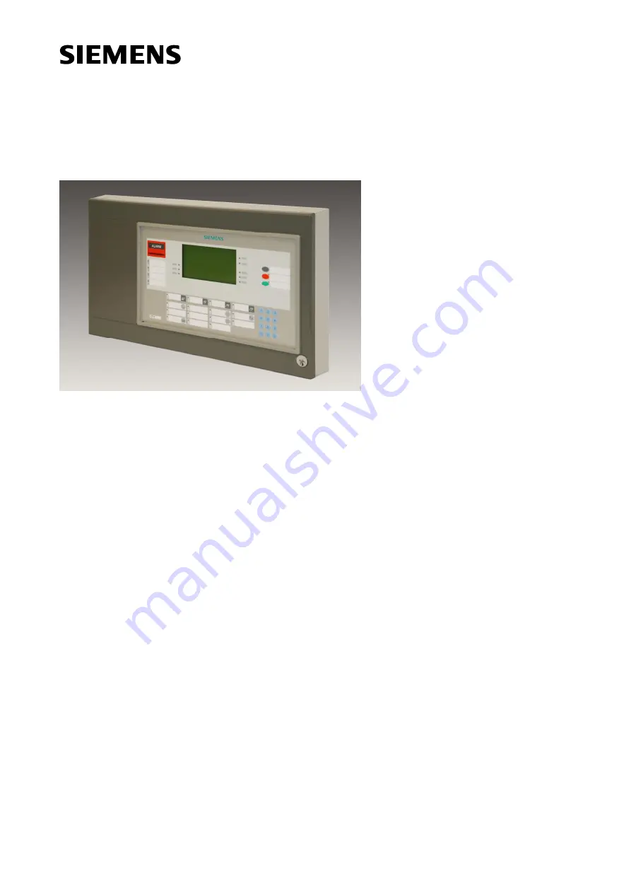
Page 86: ...arm device active Premises manned 9 1 3 4 6 7 8 2 10 5 Œ Text display field display with yellow lighting and corresponding buttons Appears yellow for all messages or during operation is automatically switched off if system is not being operated dark if there are no danger messages and no user activities are taking place ALARM field lights up when there is an alarm signal Ž Display fields sometimes...
Page 87: ...are A distinction is made between the following operating elements Display buttons Function keys Numerical key pad Key switch Where is there a detailed descrip tion All the terminal display and operation elements are described in detail in the corresponding chapters The following pages contain a somewhat detailed view of the elements Terminal vari ants Standard terminal B3Q661 Nordic terminal B3Q6...
Page 88: ...splay information during user queries LEDs LEDs are used to Display a particular AlgoRex system operating state Guide the user through a particular process Optical displays The various optical displays are shown in the following figure LEDs LEDs Display LEDs Faults Information Alarms Alarm device fault Remote transmission fault Alarm device off Remote alarm off System on Detector test mode System ...
Page 89: ...ages e g scrolling and selecting messages operating the menu and activating functions from the menu Function keys There are a number of function keys on the AlgoPilot terminal These provide direct access to certain functions Numerical key pad For inputting numerical values such as passwords or addresses The numerical key pad also includes the confirmation button ü and delete button Õ Key switch Th...
Page 90: ...is in normal operation and there are no messag es to display What is displayed The standby display indicates Time and date Text which can be defined by the user maximum 6 lines Operate softkey Example The standby display may for example look like this Siemens AlgoRex Fire detection system Version EP7F Z1 Responsible 6789 Joe Example Phone 04 SEP 2002 10 35 Operate ...
Page 91: ...matically called up Example of user intervention us ing menu softkeys The system is providing the user with information about 2 pending alarms The corresponding menu is displayed at the same time The user can use the corresponding softkeys to call up the measure text Œ to display the functions for the message selected or to go to the main menu Ž or to display the elements in alarm condition 1 2 3 ...
Page 92: ...functions can also be combined in sub menus The menu is tree like in structure with various levels of branches Navigation softkeys allow the user to switch between menus There is at least one softkey for navigation in each menu Labeling of softkeys A softkey s labeling indicates it basic functionality It may be a function which is performed im mediately e g LED test or take you to a sub menu e g H...
Page 93: ... have a hierarchy structure This produces a menu tree Menu extension If too many functions need displaying on one and the same hierarchical level the menu can be extended But this is not the same thing as a sub menu because here all the softkeys are at the same hierarchical level Status dependency The menu only shows permitted functions It is therefore dependent on the status of the corre sponding...
Page 94: ... primary menu press the Escape softkey Accessing message specific func tions To edit messages on the display use the category selection keys and scroll keys to select the corresponding message Then press the Functions for sel message softkey to go to the menu with all the functions available for the specific message Example Accessing sub menu Since there are a lot of sub menus it is not worth list...
Page 95: ...ected back to the previ ous page Select Select Lower level Higher level Go to Navigation within the logical and physical tree structure Back to MAIN MENU Goes from any position in a sub menu back to the main menu Back Goes from a sub menu back to the last menu Escape Goes from the main menu back to the primary menu Õ This button has the same function as Abort but functions at the sub menu level If...
Page 96: ...on level has its own password Password Properties The password is made up of up to 8 characters A password is defined for a particular authorization level It is defined by the service engineer in the system configuration Password prompt A text on the display requesting the password Password input The user enters the password Key switch The key switch grants access to users with a key This user doe...
Page 97: ... available depend on the authorization level FSee chapter Function lists 4 on page 129 Changing au thorization level There are two ways of changing authorization level Entering a password Activating the key switch if present A Mixed form is also possible where you activate the key switch if present to e g go to au thorization level 2 1 and later enter a password to go to a higher level When can au...
Page 98: ...ith a password or The user logs in first and then starts the operation This method is used when accessing with a key switch The main menu appears once the user has logged in Start End Yes No No Yes You decide to just trying to start to operate You may be logged in from an earlier operation Start to operate Already logged in Login procedure Login procedure Start to operate Continue to operate You d...
Page 99: ...es manned 2 Logging in with password Logging in using key switch Enter password using Πnumerical keys Turn key switch if present This is the most flexible way of logging in This way of logging in provides access to various authorization levels depending on the password entered Logging in with a key switch only provides access to one authorization level If you need to access a higher level you can...
Page 100: ...ologies A6V10225450_b_en_ Fire Safety 2017 09 07 Logging in continued Password input Detailed description of how to enter a password ok End Yes No No Yes Start Enter digits 0 9 Wrong digit Press key Password completed Press key or select softkey ...
Page 101: ... a password But it can be used to explicitly log out Logging out us ing the timeout Operation is automatically blocked if no keys have been pressed for a certain length of time timeout 1 10 minutes or 0 timeout 0 means No automatic logout Service engineer set ting The user is of course not automatically logged out when the key is in the horizontal position Logging out us ing the keypad The figure ...
Page 102: ...2 Building Technologies A6V10225450_b_en_ Fire Safety 2017 09 07 Logging out continued Logging out with the key Only possible if the user logged in with the key switch Logged in Turn key to vertical position Remove key Logged out ...
Page 103: ...nd out Navigation paths Navigation during the log in out phase depends a lot on how the menu is used See diagram be low Changing from primary to main menu et vice versa LoggedIN Prim aryM enu M ainM enu Operate Escape Timeout Password entry Keyswitch ON Password entry Keyswitch ON Key 0 9 Password query Password query Keyswitch OFF Keyswitch ON Key 0 9 Operate P rim aryM enu LoggedO U T Logout Log...
Page 104: ...nse 4 Representation on the terminal Faults Information Alarms 1 2 3 4 Alarms category Faults category Isolation category Information category If there is a message the LED for this category lights up Properties The table below shows the properties for the various messages Alarm Fault Isolation Information How are the messages displayed All messages are displayed spontaneous ly All messages are di...
Page 105: ...gade REQUESTED Total 2 01 AUTOM Fire ALARM Main building 1st floor Room 104 Intervention text Function for sel message Operate 02 AUTOM FIRE ALARM Main building 1st floor Corridor Example of message of the FAULT category FAULTS Total 3 01 AUTOM Fire ALARM Main building 1st floor Room 104 Short message Function for sel message Operate 02 AUTOM FIRE ALARM Main building 1st floor Corridor Example of ...
Page 106: ...Remote transmission fault System fault Remote alarm off Detector test mode Premises manned ALARM Œ ALARM bar lights up 01 Autom Brandalarm Hauptgebäude 1 Stock Raum 104 Feuerwehr aufgeboten Total 2 02 Autom Brandalarm Hauptgebäude 1 Stock Korridor Alarm e quittieren durch Drücken der Taste Quittieren Massnahmentext Funktionen für gewählte Meldung Bedienung Display shows the alarm message s Note Th...
Page 107: ... at any time or just when there are alarms R em otealarm ac tive Remote alarm active LED lights up when the remote transmis sion of alarms is active A larmdelay off Alarm delay off LED lights up if the alarm delay is switched OFF If the relevant Alarm delay off key is pressed the active re mote alarm transmission delay is stopped This results in imme diate remote transmission Scrolling through ala...
Page 108: ...us are reset A message appears on the display while the system is undertak ing the acknowledgement Resetting alarm s Resetting returns the system to standby Reset Pressing the Reset button results in External horn stops sounding CAK is reset Controls which depend on the acknowledged and active sta tus are reset A message appears on the display while the system is resetting Handling alarms which ca...
Page 109: ...Basic system information 109 Building Technologies A6V10225450_b_en_ Fire Safety 2017 09 07 This page is left empty on purpose ...
Page 110: ...building 1st floor Room 104 Intervention text Function for sel message Operate Elements in ALARM 02 AUTOM FIRE ALARM Main building 1st floor Corridor Plan 063 01 01 004 Operator guidance text Prompts the operator to undertake the right actions in a particular situation Fire brigade REQUESTED Total 2 01 AUTOM Fire ALARM Main building 1st floor Room 104 Intervention text Function for sel message Ope...
Page 111: ... Fire ALARM Main building 1st floor Room 104 Intervention text Function for sel message Operate Elements in ALARM 02 AUTOM FIRE ALARM Main building 1st floor Corridor Menu selection key to display the intervention text The measures text is displayed as follows Fire brigade REQUESTED Total 2 01 AUTOM Fire ALARM Main building 1st floor Room 104 Intervention text Escape 02 AUTOM FIRE ALARM Main build...
Page 112: ...sage Operate Elements in ALARM 02 AUTOM FIRE ALARM Main building 1st floor Corridor Top line Alarm message s Number of alarms State of the remote 1 alarm scroll box last alarm Scroll keys Element information st Guidance text Intervention text Function keys for operation Top line Displays the following information Number of alarms Status of remote alarm transmission Possible messages Fire brigade R...
Page 113: ...tinued Scroll keys For scrolling through alarm messages if there are more than two such messages Function keys Context dependent functions such as Displaying measures texts Functions for selected messages Operating Go to main menu User guidance Text which prompts the operator of how to respond in a particular situation ...
Page 114: ...ire detectors when the system is in Manned operating mode Checks whether anyone has acknowledged the danger alarm within a pre programmed time But if this time passes without acknowledgement the alarm is transmitted to the fire brigade The time remaining is shown on the display in minutes and seconds V2 alarm inves tigation time This is a countdown which is active for automatic fire detectors when...
Page 115: ...ef V1 time to give the person re sponsible time to decide what measures to take This person will generally acknowledge the alarm which triggers the V2 time The fire lo cation can be found during this time At the fire location you must decide whether it is a real fire and whether the fire brigade has to intervene If this is the case the nearest manual call point should be activated In the case of a...
Page 116: ... are temporarily switched off Examples Some system parts which can be temporarily switched off are zones elements horns remote transmission printer i Switching off system parts prevents them functioning The Isolation function must therefore be used with great care As soon as the conditions are normal again any switched off system parts must be switched back on again straightaway Information What i...
Page 117: ...rks in active alarm readiness It is only switched off in exceptional cases e g to test the monitoring functions How is the Remote transmission switched off All types of remote transmission can be switched off on using the menu There is however a separate function key for switching off the remote transmission of fire alarms LED and button for remote alarm transmission Relates to the following termi...
Page 118: ...able LED and button for switching off alarm devices Relates to the following terminal button and LED Alarm device off Ê button for switching over Ë LED indicates the OFF status 1 2 Alarm device active Button Œ Performs switching over LED ON Alarm device off OFF Alarm device stand by Activating alarm devices The alarm devices of a specific area can be activated via the menu A separate function key ...
Page 119: ...n the terminal This means that neither acoustic alarm devices nor remote transmission functions are activated Test alarms are saved in the event memory and logged spontaneously if there is a printer con nected Recommenda tions regarding test condition Run function test on regular basis The intervals between these tests are defined by the ser vice engineer Only ever set the fire detector of one SEC...
Page 120: ...Basic system information 120 Building Technologies A6V10225450_b_en_ Fire Safety 2017 09 07 This page is left empty on purpose ...
Page 121: ...oted that this index is a relative value where 2 means sensitivity higher by a factor of 2 compared with a parameter set with index 1 This means that the during measurements in the CEN smoke tunnel according to EN54 the detector will be activated at half the smoke density An AlgoRex smoke sensitivity index of 0 means No alarm if just smoke is present What does Response time mean This is the approx...
Page 122: ...al influence 4 with max thermal influence 110 sec 110 sec APS015S DOT1151 52 DOT1151 Ex 1 without thermal influ ence 2 with max thermal influence 85 sec 85 sec APS019S 2 without thermal influ ence 4 with max thermal influence 85 sec 85 sec APS081S 4 without thermal influ ence 8 with max thermal influence 60 sec 30 sec APS082S for China only Similar to APS005S but with adapted thermal detection par...
Page 123: ...15x i e no carbon monoxide evaluation The carbon monoxide evaluation is only activated by selecting one of the special parameter sets for DOTE1152 These parameter sets are labeled as SE The detector DOTE1152 is a very powerful smoke detector according to EN54 7 It is not a carbon monoxide warning device and it will never indicate a carbon monoxide warn ing to the control panel Parameter sets avail...
Page 124: ...the display Lamp test What is the pur pose of the Lamp test To test that all indicators LEDs the display and the alarm buzzer are functioning correctly All the terminal s optical and acoustic devices are activated for a few seconds Accessing the lamp test The lamp test is accessed via the station menu Time and date The time and date do not normally need correcting The time and date are set by the ...
Page 125: ... neighbors Example of a section st Section 1 floor ASECTION fire Select AREA Select ZONE Back to MAIN MENU 01 Ground floor 02 First floor Call POINT zone functions DETECTOR zone functions 03 Second floor What is a Zone A zone normally covers one room in a building for collective detectors several rooms It is the logical name for a detector zone comprising at least one detector Automatic fire detec...
Page 126: ...tors and manual call points are processed in different ways i e the Cerberus alarm concept is activated Interactive detectors may also have a different sensitivity level depending on the Manned or Unmanned operating mode and depending on the parameter set Changeover methods A changeover can take place Automatically Manually using the menu Manually using a button NOTE If several systems organized a...
Page 127: ... query is started If there is no operating access then the pass word query is started Confirmation query is displayed Display shows the new operating state 2 6 Faults Information Alarms 1 2 3 4 5 6 0 7 8 9 Alarm device fault Remote transmission fault Alarm device off Remote alarm off System on Detector test mode System fault Alarm delay off Remote alarm active Alarm device active Premises manned 1...
Page 128: ...h every subsequent input Operation timeout Defines the delay time during which the system waits for an operating process before the cur rent message appears again This timeout can be configured for operation with and without pending alarms Background lighting timeout Defines the period for which the display background lighting remains lit after user input This timeout can be configured depending o...
Page 129: ...OLATION messages ü ü Ê INFORMATION messages ü ü Ê TEST ALARM messages ü ü Ê SECTION Ê DETECTOR zone functions ü ü ü Ê ALL DETECTOR zones OFF with without time limit ü ü ü Ê ALL DETECTOR zones ON ü ü ü Ê ALL DETECTOR zones TEST ü ü ü Ê ALL DETECTOR zones TEST OFF ü ü ü Ê ALL DETECTOR zones INSTALLATION ü ü ü Ê ALL DETECTOR zones INSTALLATION TEST OFF ü ü ü Ê CALL POINT zone functions ü ü ü Ê All CA...
Page 130: ... ü Ê Zone INSTALLATION TEST ü ü ü Ê Zone INSTALLATION TEST OFF ü ü ü Ê Zone RENOVATION ü ü ü Ê Zone RENOVATION OFF ü ü ü Ê Zone Activate FAULT TEST ü ü ü Ê ACTIVATE zone ü Ê Zone manual call points zone digital Ê Zone OFF with without time limit ü ü ü Ê Zone ON ü ü ü Ê TEST functions ü ü ü Ê Zone TEST ü ü ü Ê Zone TEST OFF ü ü ü Ê Zone Activate FAULT TEST ü ü ü Ê ACTIVATE zone ü Ê DEACTIVATE zone ...
Page 131: ...t functions Ê CHANGE parameter set Ê Parameter set DEFAULT Ê Element FD20 Ê Poll INFORMATION ü ü ü Ê Element OFF ü ü ü Ê Element ON ü ü ü Ê ACTIVATE element ü ü Ê DEACTIVATE element ü ü Ê Element Other Ê Poll INFORMATION ü ü ü Ê Element OFF ü ü ü Ê Element ON ü ü ü Ê Device replace mode ON ü ü Ê Device replace mode OFF ü ü Ê ACTIVATE element ü ü Ê DEACTIVATE element ü ü Ê Control elements Ê Poll I...
Page 132: ...ns ü ü ü Ê See chapter FIRE ALARM SIGNAL operation starting on page 129 Ê Extinguishing functions ü ü ü Ê Blocking functions ü ü ü Ê BLOCKING autom man exting ü ü ü Ê ENABLE autom man exting ü ü ü Ê BLOCKING autom exting ü ü ü Ê ENABLE autom exting ü ü ü Ê Test functions ü Ê Initiate TEST horn ü Ê Initiate TEST warning panel ü Ê Exting control TEST ü Ê Exting control TEST OFF ü Ê Exting control RE...
Page 133: ...apter FIRE ALARM SIGNAL operation starting on page 129 Ê Zone zone control Ê See chapter FIRE ALARM SIGNAL operation starting on page 129 Ê Element interactive Ê See chapter FIRE ALARM SIGNAL operation starting on page 129 Ê Element other Ê See chapter FIRE ALARM SIGNAL operation starting on page 129 Ê Control elements Ê See chapter FIRE ALARM SIGNAL operation starting on page 129 ...
Page 134: ...e chapter FIRE ALARM SIGNAL operation start ing on page 129 Ê Section Ê All ZONES OFF ü ü ü Ê All ZONES ON ü ü ü Ê Zone Ê See chapter FIRE ALARM SIGNAL operation starting on page 129 Ê Element digital Ê See chapter FIRE ALARM SIGNAL operation starting on page 129 Ê Control elements Ê See chapter FIRE ALARM SIGNAL operation starting on page 129 ...
Page 135: ...MEMORY ü Ê Poll EVENT MEMORY ü ü ü Ê All messages ü ü ü Ê ALARM messages ü ü ü Ê FAULT messages ü ü ü Ê ISOLATION messages ü ü ü Ê INFORMATION messages ü ü ü Ê TEST ALARM messages ü ü ü Ê Station CC11 Ê Poll INFORMATION ü ü Ê Printer OFF ü ü Ê Printer ON ü ü Ê Initiate PRINTER TEST ü ü Ê Delete EVENT MEMORY ü Ê Poll EVENT MEMORY ü ü Ê All messages ü ü Ê ALARM messages ü ü Ê FAULT messages ü ü Ê IS...
Page 136: ...FF ü Ê Stub line forward ü Ê Stub line backward ü Ê Detector line TEST ü Ê Detector line TEST OFF ü Ê FU A line card Ê Poll INFORMATION ü ü ü Ê FU A line Ê Poll INFORMATION ü ü ü Ê Reconfigure D Bus ü ü Ê Readdress D Bus ü ü Ê Device read in ü Ê Localization by INSERTION ü Ê Localization by ACTIVATION ü Ê Detector line NORMAL MODE ü Ê Detector line OFF ü Ê Detector line TEST ü Ê Detector line TEST...
Page 137: ... Detector line NORMAL MODE ü Ê Detector line TEST ü Ê Detector line TEST OFF ü Ê FU FD20 line card Ê Poll INFORMATION ü ü ü Ê Reconfigure D Bus ü ü Ê Detector line OFF ü Ê Detector line NORMAL MODE ü Ê Detector line TEST ü Ê Detector line TEST OFF ü Ê FU Collective line card Ê Poll INFORMATION ü ü ü Ê Detector line TEST ü Ê Detector line TEST OFF ü Ê FU Power supply monitoring Ê Poll INFORMATION ü...
Page 138: ... OFF ü ü ü Ê Alarm horn START ü ü ü Ê Alarm horn STOP ü ü ü Ê Alarm horn TEST ü ü ü Ê Remote transmission Ê REMOTE transm fire ON ü ü ü Ê REMOTE transm fire OFF ü ü ü Ê REMOTE transm fault ON ü ü ü Ê REMOTE transm fault OFF ü ü ü Ê REMOTE transm other ON ü ü ü Ê REMOTE transm other OFF ü ü ü Ê Alarm counter Ê Poll counter REMOTE ALARMS ü ü ü Ê oll counter FIRE ALARMS ü ü ü ...
Page 139: ...horization level 1 2 1 2 2 3 Ê Enter LOGICAL ADDRESS CSX ü ü ü Ê Enter PLAN NUMBER ü ü ü SETTINGS Authorization level 1 2 1 2 2 3 Ê Display contrast brighter ü ü ü Ê Display contrast darker ü ü ü Ê Buzzer volume quieter ü ü ü Ê Buzzer volume louder ü ü ü Ê Reconfigure C bus ü ü Ê Set time and date ü ü ...
Page 140: ...dquarters Theilerstrasse 1a CH 6300 Zug Tel 41 58 724 2424 www siemens com buildingtechnologies Siemens Switzerland Ltd 2009 Technical specifications and availability subject to change without notice Document no A6V10225450_b_en_ Manual CS11 2 Edition 2017 09 07 Register 7 ...