background image

s


________________________________________________________________________________  

Siemens Energy & Automation, Inc.    3333 Old Milton Parkway Alpharetta, GA 30202


25


Starter Dimensions: 


All dimensions are shown in inches 

Catalog Number 

MH 

MW 

72EG34AFP – 72KG34AFP 

11.50 

11.00 

5.63 

10.75 

10.25 

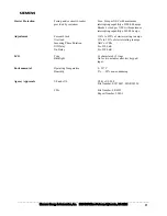
72LG34AFP – 72PG34AFP 

11.50 

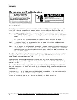
11.00 

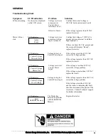
7.13 

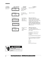
10.75 

10.25 

72RG32AFP 12.00 

16.75 

7.16 

11.00 

15.75 

72EG35AFP – 72KG35AFP 

11.50 

11.00 

5.63 

10.75 

10.25 

72LG35AFP 11.50 

11.00 

7.13 

10.75 

10.25 

72MG35AFP – 72PG35AFP 

12.00 

16.75 

7.13 

11.00 

15.75 

 
Note:  All panel mounting holes are 5/16”.  Starter and Fault contactor can extend up to ¼” 
beyond the width of the mounting panel.

Summary of Contents for 72EG34AFP

Page 1: ...s Class 72G Starter Set up Guide for Hydraulic Elevator Pump Motors SFIS 72G00 0905 September 2005 ...

Page 2: ...the purpose of this manual and product labels CAUTION indicates a potentially hazardous situation which if not avoided may result in minor or moderate injury QUALIFIED PERSON For the purposes of this manual and product labels a qualified person is one who is familiar with the installation construction operation or maintenance of the equipment and the hazards involved In addition this person has th...

Page 3: ... Fault Menus Selectable Stall Prevention User selectable Dynamic based upon average start time Instantaneous senses stall condition and reacts immediately or Time Based Adjustable Current Limit Allows precise control during starting Table of Contents Special Features 3 Starter Selection 4 Features Overview 6 Control Power Connections 7 Motor Connections 10 Inside Delta Motor Wiring 10 In Line Moto...

Page 4: ...89 72KG34AFP 25 30 60 80 26 100 93 340 72LG34AFP 30 40 75 105 35 131 121 447 72MG34AFP 40 50 100 130 43 163 151 553 72NG34AFP 50 60 125 156 52 196 181 663 72PG34AFP In Delta Configuration 75 100 252 83 315 292 1071 72RG32AFP Table 2 In Delta 460 575 Volt starter ratings HP 460V HP 575V Rated Current Amps Overload Range Amps Current Limit Range Amps Manufacturer Catalog Number 15 20 22 7 27 26 94 7...

Page 5: ...13 49 45 166 72KG34AFP 10 15 30 42 15 57 53 196 72LG34AFP 15 20 40 55 20 75 70 257 72MG34AFP 20 25 50 68 24 93 87 319 72NG34AFP 25 30 60 80 29 112 104 382 72PG34AFP In Line Configuration 40 50 130 48 181 168 618 72RG32AFP Table 4 In Line 460 575 Volt starter ratings HP 460V HP 575V Rated Current Amps Overload Range Amps Current Limit Range Amps Manufacturer Catalog Number 10 15 18 6 25 24 85 72GG3...

Page 6: ...ides overload current imbalance reverse phase single phase and shorted SCR protection In addition to those faults on power up the starter will check the motor configuration Power wiring terminations Liquid Crystal Display Port for Infrared or Serial Communication Ground Screw The Fault Contactor provides a means for interrupting current during shorted SCR conditions It DOES NOT provide electrical ...

Page 7: ...ls 1 and 2 are internally connected An external jumper wire is required to connect terminal 1 to terminal 9 to feed the NO Ready contacts Figure 2 Control Power Connections The customer control connections on the Solid State Elevator Starter feature a removable terminal block The layout is shown to the left All terminations are screw type To Contactor Terminals 1 and 2 are tied internally in unit ...

Page 8: ...l a control board that the unit is in a fault condition Terminal 9 should be connected via a jumper wire to either terminal 1 or 2 This provides a hot feed to the fault contactor coil when the NO Ready contact is closed The terminals marked 10 and 11 are the switched side of the NO Ready contact This configuration allows terminal 10 to be used to signal that the starter is ready to run while termi...

Page 9: ...___ Siemens Energy Automation Inc 3333 Old Milton Parkway Alpharetta GA 30202 9 Typical Control Power Connections Figure 3 The figure above shows a typical control wiring diagram While this diagram may not apply to all installations it does show various connections to the starter ...

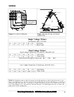
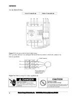
Page 10: ...Inside Delta Motor Wiring The motor wiring should be connected exactly as shown in Figure 4 If it is not the starter will detect a motor wiring error If you have elected to cycle the fault contactor on each start you must contact technical support for directions on configuring the starter and wiring in a required off delay timer Figure 4 Power Wiring for In Delta Configuration ...

Page 11: ...her in the motor 4 7 5 8 6 9 Low Voltage Connections 12 lead motor 220 240 VAC T1 T2 T3 T6 T4 T5 1 7 2 8 3 9 6 12 10 4 11 5 Soft Starter Motor Leads Note This Solid State starter is wired at the factory for in delta operation on 6 and 12 lead motors only If you have a 9 lead delta motor you must run it as the In Line configuration show on the following page If you have a submersible application wh...

Page 12: ...Inc 3333 Old Milton Parkway Alpharetta GA 30202 12 In Line Motor Wiring Line Connections Motor Connections Figure 5 Conversion for In Line Applications It is up to the end user to reconfigure the leads from the starter to the fault contactor for In Line operation Figure 5a Motor wiring for in line Applications ...

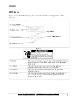
Page 13: ...Enter Menu Button Figure 6 Up Button This key is used to move up in all of the menu structures It also is used to increase or select different parameters in the parameter adjust mode Exit Button This key is used to exit menus and to exit the parameter adjustment menus after selections have been made Enter Button This key is used to enter menus and to enter the parameter adjustment menus Down Butto...

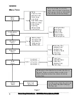
Page 14: ... Password Use this menu to Reset the starter and access further information through the Password Starting Amps Overload Amps Line Rotation Off Delay Ms Set On Delay Ms Power On Time Running Time Starting Time Number of Starts Power Ups View Total Faults Last Fault Last Fault 1 Last Fault 2 Select Last Fault 3 Fault Type Fault Run Status Fault Time Running Time View Fault Amps This is the default s...

Page 15: ...y increase the starting time This setting should not be less than twice the motor s FLA 425 of the starter current rating as measured in Amps Overload Amps This setting should be set at or below the FLA of the hydraulic pump motor 50 of the starter rating in Amps Line Rotation The choices for this are either ABC or CBA To change the setting from the factory default of ABC rotation select the right...

Page 16: ...VA Expected Operations rated load 10 x 106 cycles Ready Output Mechanical Relay Number of Contacts 1 Normally Open 7 8 1 Normally Closed 9 10 11 Rated Operational Current 3 0 Amps 120 VAC Make Break VA 3600 360 VA Expected Operations rated load 100 000 cycles Duty Cycle Rating Duty Cycle 30 140 of rated FLA Starts per hour 80 Motor Protection Overload Class 5 adjustment range is 33 to 125 of Rated...

Page 17: ...r NEC with maximum interrupting capability of 42 000 amps Adjustment Current Limit 116 to 425 of starters rating in amps Overload 33 to 125 of starters rating in amps Incoming Phase Rotation ABC or CBA Off Delay 0 to 2500 mS On Delay 0 to 2500 mS LCD Type 16 characters by 2 lines Backlight On for two minutes after last keypad input Environmental Operating Temperature 0 50 C Humidity 5 95 non conde...

Page 18: ...ontrollers After a Fault Condition of NEMA standard ICS 2 1993 Industrial Control and Systems Controllers Contactors and Overload Relays Rated Not More Than 2000 Volts AC or 750 Volts DC This checklist does not represent an exhaustive survey of maintenance steps necessary to ensure safe operation of the equipment Particular applications may require further procedures Should further information be ...

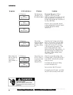
Page 19: ... screen still displays Ready replace the starter LCD indicates Voltage too low at Control Power Input If the voltage is less than 105 VAC correct the voltage problem If the voltage is greater than 105 VAC replace the starter LCD indicates Voltage too low at Control Power Input If the voltage is less than 105 VAC correct the voltage problem If the voltage is greater than 105 VAC replace the starter...

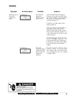
Page 20: ...rotor is spinning in the correct direction If the rotor does not turn in the correct direction change the incoming phases back to their original connections and change the Line Rotation setting in the Parameter Menu LCD indicates The motor is not correctly connected to the starter Disconnect Line Power For In Delta Applications the following measurements should be less than 10 ohms t1 to center le...

Page 21: ... fault contactor be cycled with each run the starter can be configured to check for motor wiring faults only when the motor run command is initiated Consult technical support for further assistance Motor is wired correctly starter still indicates Motor Wiring fault Disconnect line power With an ohmmeter check for a shorted SCR by measuring the resistance of each phase from the line to load termina...

Page 22: ... more of the incoming lines are over 528 volts for 460 volts units or 632 volts for 575 volt units verify the reading with a meter If the meter reading matches the starter s reading correct the voltage problem If the meter reading does not agree with the starters voltage reading contact technical support Motor Starts but does not come up to speed in a timely manner or at all LCD indicates before s...

Page 23: ...a clamp on ammeter Check the voltages across the SCRs by measuring across the line and load terminals when the unit is up to speed These voltages should be less than a few volts If any are above 10 VAC contact technical support The Default trip point for the ratio of the lowest to the highest current is 33 This setting is adjustable in the OEM menu accessible via a password If the setting has to b...

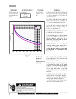
Page 24: ...is some type of viscosity control either heaters or re circulation If this is not the case contact technical support for assistance on configuring the Instantaneous Stall Protection Motor trips out on an Overload fault after coming up to speed LCD indicates The Starter has detected an Overload condition while up to Voltage The overload setting should be set to the FLA of the motor See Figure 8 for...

Page 25: ...log Number H W D MH MW 72EG34AFP 72KG34AFP 11 50 11 00 5 63 10 75 10 25 72LG34AFP 72PG34AFP 11 50 11 00 7 13 10 75 10 25 72RG32AFP 12 00 16 75 7 16 11 00 15 75 72EG35AFP 72KG35AFP 11 50 11 00 5 63 10 75 10 25 72LG35AFP 11 50 11 00 7 13 10 75 10 25 72MG35AFP 72PG35AFP 12 00 16 75 7 13 11 00 15 75 Note All panel mounting holes are 5 16 Starter and Fault contactor can extend up to beyond the width of...

Page 26: ...gy Automation Inc Siemens is a registered trademark of Siemens AG Publication No SFIS 72G00 0905 Subject to change without prior notice Printed in the U S A Siemens Energy Automation Inc 3333 Old Milton Parkway Alpharetta GA 30202 1 800 964 4114 sea info siemens com http www sea siemens com controls ...

Reviews: