background image

Siemens IK PI · 2004

6/42

AS-Interface Slaves

Introduction

I/O modules for operation in the field

6

Function

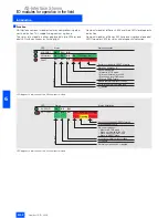
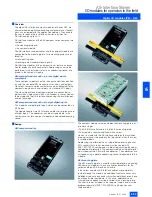
AS-Interface compact modules features comprehensive diag-
nostic indication. This supports diagnosis at a glance.

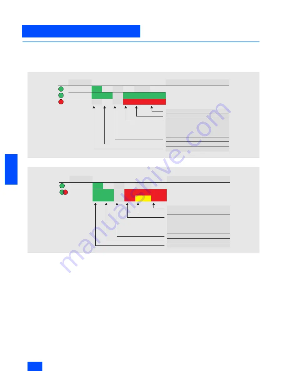
The status of a module is either displayed via two LEDs or one 
dual LED with continuous or flashing light.

Compact modules of Series K60 have three LEDs for diagnostic 
indication.

Compact modules of Series K45 have one single and one dual 
LED (two-color LED) for status and diagnostic indication.


LED diagnostic indication of the K60 compact module

LED diagnostic indication of the K45 compact module

LED

AUX PWR

1

)

AS-Interface

FAULT

NSA0_00318

States

Off

Off
Off

Off

Off

Off

Status description

On
On

On

On

On

On

On

Flashing

Flashing

Sensor overload with RESET of slaves
Slave has address = 0
No communication:

– Master in STOP mode

– Slave not entered in the LPS

– Slave has wrong IO&D code

– Slave in RESET state

Module completely without voltage
U

Aux 

failure Normal operation and

U

Aux 

applied

LED

AUX PWR
AS-i / FAULT

NSA0_00313

States

Off

Off
Off

Status description

Sensor overload with RESET of slaves
Slave has address = 0
No communication:

– Master in STOP mode

– Slave not entered in the LPS

– Slave has wrong IO&D code

– Slave in RESET state

Module completely without voltage
U

Aux 

failure

Normal operation and U

Aux 

applied

On
On

On

On

Flashing Flashing

Flashing

Summary of Contents for 50295

Page 1: ...pecial integrated solutions 6 94 AS Interface Communication modules AS Interface Slaves continued 6 98 Modules with special functions 6 98 Counter modules 6 100 Earth fault detection modules 6 103 Overvoltage protection module 6 105 AS Interface motor starters and IP65 67 load feeders 6 105 AS Interface compact starters IP65 400 V AC 6 113 AS Interface motor starters IP67 24 V DC 6 116 ECOFAST mot...

Page 2: ...connected at any point thanks to specially developed wiring and connection using the insulation displacement method This concept gives you tremendous flexibility and considerably cuts costs The AS Interface is a single master system Communications processors CPs are available for SIMATIC systems which control process or field communication as masters The system expansion now allows double the quan...

Page 3: ... actuators and sensors are physically distributed throughout the machine e g in a bot tling plant or on a production line AS Interface replaces complicated wiring harnesses and con nects binary and analog actuators and sensors such as proxim ity switches valves or indicator lights to a controller e g SI MATIC or PC In practice this means The installation runs without problems because data and powe...

Page 4: ...bles Network components such as repeaters extenders The power supply unit for supplying power to the slaves modules for connecting standard sensors actuators Actuators and sensors with integrated ASIC slave Fail safe modules for transmission of secure data through AS Interface Address programming device for setting the slave address AS Interface master for SIMATIC 0 1 Integrated interface CP 343 2...

Page 5: ...y power Connection method Contacting of the AS Interface cable using the insulation displacement method Permissible cable length max 100 m w o repeater extender 500 m range with repeater extender parallel connection of repeaters Cycle time max 5 ms with full expansion 10 ms using A B method Number of stations max 31 slaves accord to Complete AS Interface Spec V2 0 62 slaves accord to Complete AS I...

Page 6: ...y working to the new specifi cation are identified accordingly in the catalog Addressing A B slaves A B slaves can be addressed like standard slaves via all com mercial AS Interface addressing units conforming to specifica tion 2 1 AS Interface addressing units that do not conform to the new specification 2 1 can readdress A B slaves only as A slaves As far as addressing is concerned an analog sla...

Page 7: ...K2 200 0CQ20 0AA3 K45 compact module 4 inputs M12 connection 3RK2 200 0CQ20 0AA3 M8 screw type connection 3RK2 200 0CT20 0AA3 M8 snap on connection 3RK2 200 0CU20 0AA3 2 x 2 inputs 3RK2 200 0CQ22 0AA3 3 outputs 3RK2 100 1EQ20 0AA3 2 outputs 2 inputs 1 3RK2 400 1BQ20 0AA3 3RK2 400 1HQ00 0AA3 K60 compact module 8 inputs 2 outputs 3RK2 400 1HQ00 0AA3 8 inputs 3RK2 200 0DQ00 0AA3 4 inputs 3 outputs 3R...

Page 8: ...lsafe PLC or special master is not required Simple system structure due to standardized AS Interface technique Safe and non safe data on the same bus Existing systems can be expanded quickly and easily Safe signals can be combined in groups Integration of the safety signals in the plant diagnostics con cept Approved up to category 4 acc to EN 954 1 Safety at Work is certified by the German Technic...

Page 9: ...il now only two elements could be OR gated Logical AND operation In addition to the standard AND gating in the main path of an enabling circuit an AND operation can be inserted into an OR operation More than two elements can be gated in this AND Buffer Temporary shutdowns are stored in a buffer for the purpose of diagnostics Number of devices The number of devices that the safety monitor can proce...

Page 10: ...ng circuits 3RK1 105 1BE04 0CA0 Safety monitor with extended functionality One enabling circuit 3RK1105 1AE04 2CA0 Two enabling circuits 3RK1105 1BE04 2CA0 Configuration software 3RK1 802 2FB06 0GA0 Cable set 3RK1 901 5AA00 L L K1 K2 Start 1 1 13 1 23 1 Y1 AS i AS i 1 Y2 AS i 1 2 3 L M 1 32 1 14 1 24 PE K1 K2 L M N M K1 K2 M L 1 Y1 g_nsa0_xx_00356 L L Start 2 Start 1 K1 K2 K3 K4 1 13 1 23 1 Y1 AS ...

Page 11: ...fe inputs 2 standard outputs with UAux 3RK1 205 0BQ00 0AA3 3RK1 405 0BQ00 0AA3 3RK1 405 0BQ00 0AA3 AS Interface chip SAP 4 SAP 4 SAP 4 Operational voltage in accordance with AS Interface specification in V 26 5 to 31 5 26 5 to 31 5 26 5 to 31 5 Total current input in mA 45 270 270 Input connection PNP PNP PNP Inputs Sensor supply via AS Interface Sensors Mechanical switching contact Mechanical swi...

Page 12: ... closed Socket 7 and 8 Not assigned closed Not assigned closed Not assigned closed AS Interface certificate Yes Yes Yes Approvals UL CSA UL CSA UL CSA Degree of protection IP67 IP67 IP67 Earth connection PIN 5 of each M 12 socket is connected to the grounding plate in the mounting plate via a pin outputs only sockets 5 and 6 PIN 5 of each M 12 socket is connected to the grounding plate in the moun...

Page 13: ...01 2EA00 K60F safe compact module 1 2FE 2A 3RK1 405 0BQ00 0AA3 2FE 2A with UAux 3RK1 405 1BQ00 0AA3 K60 mounting plate 3RK1 901 0CA00 3RK1 901 1AA00 Input bridge for K45 K60F Black version 3RK1 901 1AA00 Red version 3RK1 901 1AA01 3RK1 901 1KA01 AS Interface M12 sealing caps protected against manipulation For spare M12 sockets one packing contains ten sealing caps 3RK1 901 1KA01 N S A 0 _ 0 0 0 2 ...

Page 14: ... and Pin 4 of Socket 1 is connected to Pin 2 of Socket 2 If both socket pairs are assigned the inputs are linked Socket Assignment data sheet function 1 Pin 1 and Pin 2 affects bits D0 and D1 Channel 1 Pin 3 and Pin 4 affects bits D2 and D3 Channel 2 Pin 5 not assigned 2 Pin 1 and Pin 2 affects bits D2 and D3 Channel 2 Pin 5 not assigned 3 Unused 4 Unused 1 2 3 4 ADDR 1 2 3 4 G_NSA0_XX_00355 Socke...

Page 15: ...ive doors guards or other covers when a dangerous state exists e g for coastdown movements of the switched off machine The safety switch with tumbler has two main tasks Enabling the machine when the protective device is closed and locked Disabling the machine when the protective device is open The position switch can only be switched using the associated coded actuator It is not possible to bypass...

Page 16: ...P65 3SF3 210 0DV00 0BA2 Molded plastic enclosure EN 50 047 50 mm wide slow action contact 1 NC Overtravel plunger 3SF3 210 0CV00 0BA2 Roller plunger 3SF3 210 0DV00 0BA2 Roller lever 3SF3 210 0EV00 0BA2 Angular roller lever 3SF3 210 0FV00 0BA2 Swivel lever 3SF3 210 0GV00 0BA2 Molded plastic enclosure EN 50 047 50 mm wide snap action contact 1 NC Overtravel plunger 3SF3 210 1CV00 0BA2 Roller plunger...

Page 17: ...l position switch Direct connection of AS Interface to Safety at Work For use up to Category 4 acc to EN 954 1 IP65 Slow action contact one NC Molded plastic enclosure Side and front operation 52 mm wide 30 N extraction force 3SF3 257 6XX00 0BA2 5 N extraction force 3SF3 257 6XX40 0BA2 Automatic ejection 3SF3 257 6XX30 0BA2 Actuator Standard Width length of enclosure 27 mm rmin 150 mm 3SX3 218 Uni...

Page 18: ...le operated switch are positively driven The AS Interface cable operated switches are ready to operate after pretensioning of the pull wire or the rope When the rope is pretensioned it must be released before the cable operated switch can be returned to the original state Selection and Ordering data 1 Accessories technical specifications contact travel circuit diagrams and dimensional drawings are...

Page 19: ...nstructions for the respective devices Benefits Double scan function Cascading of host and guest devices Two transmission channels Design A SIGUARD Light Curtain or light array comprises a transmitter and a receiver that must be mounted opposite each other Depending on the resolution and length a specific number of transmit and receive diodes are arranged in a vertical row The infra red LEDs of th...

Page 20: ... for 90 mm resolution Response time of the complete system Response time 3SF7842 response time of AS Interface safety monitor max 40 ms Degree of protection IP65 Supply current in mA Max 130 transmitter Max 140 receiver Operating mode Protection mode without restart lockout Transmitter receiver synchronization Optical synchronization two transmission channels can be selected Infra red disturbance ...

Page 21: ...eceiver 3SF7 842 6BL01 1500 Transmitter 3SF7 842 6BM00 1500 Receiver 3SF7 842 6BM01 1650 Transmitter 3SF7 842 6BN00 1650 Receiver 3SF7 842 6BN01 1800 Transmitter 3SF7 842 6BP00 1800 Receiver 3SF7 842 6BP01 SIGUARD Standard Light Curtain 30 mm resolution Type 4 acc to IEC 61 496 1 2 150 Transmitter 3SF7 842 6DB00 150 Receiver 3SF7 842 6DB01 225 Transmitter 3SF7 842 6DC00 225 Receiver 3SF7 842 6DC01...

Page 22: ...0 Receiver 3SF7 842 6EP01 2100 Transmitter 3SF7 842 6ER00 2100 Receiver 3SF7 842 6ER01 2400 Transmitter 3SF7 842 6ES00 2400 Receiver 3SF7 842 6ES01 2700 Transmitter 3SF7 842 6ET00 2700 Receiver 3SF7 842 6ET01 3000 Transmitter 3SF7 842 6EU00 3000 Receiver 3SF7 842 6EU01 SIGUARD Standard Light Curtain 90 mm resolution Type 4 acc to IEC 61 496 1 2 750 Transmitter 3SF7 842 6JG00 750 Receiver 3SF7 842 ...

Page 23: ...y Type 4 acc to IEC 61 496 1 2 Sensing range in m Function 18 Transmitter 3SF7 842 6SE00 18 Receiver 3SF7 842 6SE01 18 Transmitter 3SF7 842 6PG00 18 Receiver 3SF7 842 6PG01 18 Transmitter 3SF7 842 6MH00 18 Receiver 3SF7 842 6MH01 60 Transmitter 3SF7 842 6SE50 60 Receiver 3SF7 842 6SE51 60 Transmitter 3SF7 842 6PG50 60 Receiver 3SF7 842 6PG51 60 Transmitter 3SF7 842 6MH50 60 Receiver 3SF7 842 6MH51...

Page 24: ...scanner calculates the precise coordinates of the obstruction seen from the light propagation time If the obstruction or the person is located within defined ranges a Stop function is executed Switch off is then performed via the safe interface within the system response time The Stop function is reset when the protective zone is free again depending on the operating mode either automatically or f...

Page 25: ...ecuring only live zones Route monitoring for driverless transport systems Detection of persons and objects that approach the vehicle The laser scanner offers a greater protection range than bumpers and therefore permits higher speeds Collision protection for shifting units Protection of persons who are in the path of the vehicle Objects in the path of the vehicle are detected early damage to the v...

Page 26: ...en extremely short light pulses are emitted a time difference occurs between the transmitted and received light pulse The propagation time of the light pulse is a direct measurement of the target distance The operating range of the scanner 190 is subdivided into angle segments of 0 36 Protection and warning field pairs The device has 4 switchable protection and warning field pairs LS4Soft operatin...

Page 27: ...ailures of up to 20 ms e g AS Interface power pack 3RX9 307 0AA00 Overcurrent protection 1 25 A fuse medium slow Supply current in mA Typ 350 LS4 4 AS Interface laser scanner 3SF7 834 6DD00 Inputs Restart Reset Connection of a command device for with restart lockout operating mode and or device resets dynamically monitored 24 V DC opto decoupled Zone pair switchover Selection of zone pairs via 4 c...

Page 28: ...g see assignment of SF coding P3 LS4 RESET via PC AS Interface master call Assignment of SF coding P2 0 0 1 1 P1 0 1 0 1 SF 1 2 3 4 LS4 4 AS Interface laser scanner 3SF7 834 6DD00 Assignment PIN1 PIN2 PIN3 X1 M12 plug for device connection AS i AS i X2 M12 connector for external power supply 24 V DC supply 24 V Out Mass X3 M12 socket for protective zone changeover SF pair 1 SF pair 2 SF pair 3 X4 ...

Page 29: ... 1 L E D 5 x 1 4 0 5 2 1 4 4 5 9 5 1 2 9 5 2 1 2 2 9 5 23 56 6 51 5 74 4 90 158 166 192 155 4 9 NSC 00610 9 X 2 N S C 0 _ 0 0 6 3 1 a X 3 X 4 X 1 O p t i c a l i n t e r f a c e M 1 2 c o n n e c t o r A S I n t e r f a c e M 1 2 c o n n e c t o r o p t i o n a l a u x i l i a r y v o l t a g e M 1 2 s o c k e t p r o t e c t i o n f i e l d c h a n g e o v e r A d d r e s s i n g s o c k e t A S ...

Page 30: ... in an enclosure Selection and Ordering data 1 See Catalog LV 10 Section Pushbuttons and Indicator Lamps Design Order No 3SF5 801 3AA08 AS Interface EMERGENCY STOP housing Two NC contacts AS Interface F adaptor Yellow cover 3SF5 801 3AA08 Yellow cover with protective collar 3SF5 801 3AB08 3SF5 402 1AA01 AS Interface EMERGENCY STOP front plate AS Interface F adaptor For AS Interface EMERGENCY STOP ...

Page 31: ...TIC S5 For operation in the S5 115U an adapter casing is required In I O mode 32 byte are used in the I O address space Display of the connected and activated slaves and their oper ational readiness Connection of the two AS Interface cables through connectors with terminal strip solder free connection with screw lock One pushbutton per master unit for switching the operating status and entering th...

Page 32: ...S Interface segment Power loss 7 9 W Perm environmental conditions Operating temperature 0 C to 60 C Transport storage temperature 40 C to 70 C Relative humidity max 95 at 25 C Design Module format Double height Eurocard format Dimensions W x H x D in mm 160 x 233 4 x 20 32 Weight 400 g Space required 1 slot CP 2430 communications processor 6GK1 243 0SA20 For connecting SIMATIC S5 115U 135U 155U t...

Page 33: ... the connection of the distributed I O sys tem ET 200X to AS Interface This module can be used to activate up to 31 AS Interface slaves and if bi directional slaves are implemented up to 248 binary components Up to 6 CP 142 2 can be operated on the ET 200X Design 16 byte inputs and 16 byte outputs are used in the address space of the ET 200X Operating statuses displayed by LEDs in the frontplate D...

Page 34: ...rom the AS Interface shaped cable According to the AS Interface Specification V2 0 Power loss 2 W Current consumption Through backplane bus Typ 50 mA at 24 V DC Through AS Interface from the AS Interface shaped cables According to the AS Interface specification V 2 0 Perm environmental conditions Operating temperature 0 C to 55 C Transport storage temperature 40 C to 70 C Relative humidity 95 at 2...

Page 35: ... on AS Interface per CP In addition the integrated analog value processing also makes analog values per CP max 31 analog slaves each with up to 4 channels available to the S7 200 at the AS Interface Up to two CP 243 2s can be operated simultaneously on the S7 200 Design The CP 243 2 is connected to the S7 200 like an expansion module It features Two terminals for direct connection of the AS Interf...

Page 36: ...nting 0 C to 55 C Vertical mounting 0 C to 45 C Transport storage temperature 40 C to 70 C Relative humidity Max 95 at 25 C Design Module format S7 22x expansion module Dimensions W x H x D in mm 71 2 x 80 x 62 H 16 mm with holes for wall mounting Weight Approx 250 g Space required 1 slot CP 243 2 communications processor 6GK7 243 2AX01 0XA0 For connection of SIMATIC S7 200 2nd generation to AS In...

Page 37: ... connection for SIMATIC S7 300 and ET 200M Connection to the AS Interface allows ac cess to max 248 DI 186 DO per CP The integrated analog value processing also supports evalua tion of very simple analog signals per CP at max 31 analog slaves each with four channels Design The CP 343 2 is connected to the S7 300 like an expansion module It features Two terminals for direct connection of the AS Int...

Page 38: ...tal conditions Operating temperature 0 C to 60 C Transport storage temperature 40 C to 70 C Relative humidity max 95 at 25 C Design Module format S7 300 design Dimensions W x H x D in mm 40 x 125 x 120 Weight Approx 190 g Space required 1 slot CP 343 2 communications processor 6GK7 343 2AH00 0XA0 For connection of SIMATIC S7 300 and ET 200M to the AS Interface without front connector Front connect...

Page 39: ...8 DI 186 DO per CP The integrated analog value processing also supports evalua tion of very simple analog signals per CP at max 31 analog slaves each with four channels The CP 343 2 P functionality is identical to that of the CP 342 2 An old S7 user program can therefore be used with the new CP without any limitations Also the AS Interface configuration can be downloaded or uploaded with the STEP ...

Page 40: ...ironmental conditions Operating temperature 0 C to 60 C Transport storage temperature 40 C to 70 C Relative humidity max 95 at 25 C Design Module format S7 300 design Dimensions W x H x D in mm 40 x 125 x 120 Weight Approx 190 g Space required 1 slot Configuration software Optional STEP 7 V5 2 or later CP 343 2 P communications processor 6GK7 343 2AH10 0XA0 For connection of SIMATIC S7 300 and ET ...

Page 41: ...t carry ing capacity outputs Slave Type Pin assignment Connection technique Order No K60 digital 8 Inputs 2 Outputs 2 A A B special M12 3RK2 400 1HQ00 0AA3 8 Inputs Standard Y II 3RK1 200 0DQ00 0AA3 A B new 3RK2 200 0DQ00 0AA3 4 Inputs 4 Outputs 2 A Standard 3RK1 400 1DQ00 0AA3 Standard 3RK1 400 1CQ00 0AA3 1 A Y II 3RK1 400 1DQ01 0AA3 Standard 3RK1 400 1DQ03 0AA3 4 Inputs 3 Outputs 2 A A B Y II 3R...

Page 42: ...ndication of the K45 compact module LED AUX PWR1 AS Interface FAULT NSA0_00318 States Off Off Off Off Off Off Status description On On On On On On On Flashing Flashing Sensor overload with RESET of slaves Slave has address 0 No communication Master in STOP mode Slave not entered in the LPS Slave has wrong IO D code Slave in RESET state Module completely without voltage UAux failure Normal operatio...
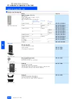
Page 43: ...with up to eight digital inputs This module has eight digital inputs which can be connected via M12 plugs The module requires two AS Interface addresses for processing all eight inputs The addresses can be assigned here in the same manner as for a compact module via a double addressing socket Design K60 compact module The compact modules are mounted on the mounting plate in just two work stages Th...

Page 44: ...E 0106 PELV Safety Class III 8 inputs 2 outputs 8 inputs 8 inputs new 2 A A B slave Standard slaves A B slaves Special assignment Y II assignment Y II assignment 3RK2 400 1HQ00 0AA3 3RK1 200 0DQ00 0AA3 3RK2 200 0DQ00 0AA3 Total current input in mA 300 270 270 Socket assignment inputs PIN 1 Sensor supply L PIN 2 Data input II PIN 3 Sensor supply L PIN 4 Data input I PIN 5 Earth connection PIN 1 Sen...

Page 45: ...IN2 D1 Socket 2 PIN4 IN2 D1 PIN2 4 IN2 D1 PIN4 IN2 D1 Socket 3 PIN4 IN3 D2 PIN2 IN4 D3 PIN2 4 IN3 D2 PIN4 IN3 D2 PIN2 IN4 D3 Socket 4 PIN4 IN4 D3 PIN2 4 IN4 D3 PIN4 IN4 D3 Socket 5 PIN4 OUT1 D0 PIN2 OUT2 D1 PIN4 OUT1 D0 PIN4 OUT1 D0 PIN2 OUT2 D1 Socket 6 PIN4 OUT2 D1 PIN4 OUT2 D1 PIN4 OUT2 D1 Socket 7 PIN4 OUT3 D2 PIN2 OUT4 D3 PIN4 OUT3 D2 PIN4 OUT3 D2 PIN2 OUT4 D3 Socket 8 PIN4 OUT4 D3 PIN4 OUT4 ...

Page 46: ...d slaves Standard slaves Y II assignment Y assignment Y II assignment 3RK1 200 0CQ00 0AA3 3RK1 400 1DQ02 0AA3 3RK1 100 1CQ00 0AA3 Total current input in mA 270 270 270 Socket assignment inputs PIN 1 Sensor supply L PIN 2 Data input II PIN 3 Sensor supply L PIN 4 Data input I PIN 5 Earth connection PIN 1 Sensor supply L PIN 2 Data input II PIN 3 Sensor supply L PIN 4 Data input I PIN 5 Earth connec...

Page 47: ...ired Hole spacing is compatible to K45 mounting plate for wall mounting Standard rail mounting Standard mounting rail wall mounting On shaped bracket the corre sponding slide rings are re quired Hole spacing also compatible to coupling module FK FK E application module Note Additional seals are only necessary when the flat cables terminate inside the module 3RK1 902 0AR00 Additional seals are only...

Page 48: ...ts 2 A A B Y II 3RK2 400 1FQ03 0AA3 4 Inputs 2 Outputs Standard 3RK1 400 1MQ00 0AA3 4 Inputs 3RK1 200 0CQ00 0AA3 2 x 2 Inputs 2 x 2 Outputs 1 A Y 3RK1 400 1DQ02 0AA3 4 Outputs 2 A Y II 3RK1100 1CQ00 0AA3 Accessories 3RK1 901 0CA00 K60 mounting plate To fit all K60 compact modules Wall mounting 3RK1 901 0CA00 Mounting onto standard rails 3RK1 901 0CB00 3RK1 901 1KA00 AS Interface M12 sealing caps F...

Page 49: ...2 I n p u t s i g n a l b r i d g e d w i t h P i n 4 P i n 3 S u p p l y L P i n 4 I n p u t s i g n a l b r i d g e d w i t h P i n 2 P i n 5 E a r t h c o n n e c t i o n N S A 0 _ 0 0 0 0 8 a 1 2 4 3 5 Y c a b l e s i n g l e c a b l e P i n 1 S u p p l y L P i n 2 I n p u t s i g n a l 2 P i n 3 S u p p l y L P i n 4 I n p u t s i g n a l 1 P i n 5 E a r t h c o n n e c t i o n N S A 0 _ 0 0 ...

Page 50: ... E a r t h c o n n e c t i o n 1 2 4 3 5 N S A 0 _ 0 0 0 0 9 a P i n 1 P i n 2 O u t p u t s i g n a l 2 P i n 3 S u p p l y L P i n 4 O u t p u t s i g n a l 1 P i n 5 E a r t h c o n n e c t i o n N S A 0 _ 0 0 0 1 1 1 2 4 3 5 1 2 4 3 5 S i n g l e c a b l e P i n 1 P i n 2 O u t p u t s i g n a l 2 P i n 3 S u p p l y L P i n 4 O u t p u t s i g n a l 1 P i n 5 E a r t h c o n n e c t i o n L e...

Page 51: ...emented with even greater consistency For IP68 test conditions see Section Tests IP68 IP69K Cleaning with pressurized cleaning equipment as is frequently necessary in the food beverages and tobacco industries is problem free IP69K When trailing cables are used many users require that the AS Interface bus cable is routed in a round cable The K60R module permits direct connection to a round cable An...

Page 52: ...R modules The voltage drop resulting from the ohmic resistance approx 0 11 W m must be taken into account The total maximum load for all four connec tions of the round cable distributor 3RK1901 1NR00 is 4 A In applications with only round cables the AS Interface bus ca ble and the 24 V DC power supply can be routed together up to 20 m when using a round cable 4 x 1 5 mm With longer cables routing ...

Page 53: ... ID ID2 code 0 F Assignment of data bits Socket 1 data bit D0 PIN2 4 IN1 D0 Socket 2 data bit D1 PIN2 4 IN2 D1 Socket 3 data bit D2 PIN2 4 IN3 D2 Socket 4 data bit D3 PIN2 4 IN4 D3 Socket 5 data bit D0 PIN4 OUT1 D0 Socket 6 data bit D1 PIN4 OUT2 D1 Socket 7 data bit D2 PIN4 OUT3 D2 Socket 8 data bit D3 PIN4 OUT4 D3 4 inputs 4 outputs IP68 IP69K Standard assignment 3RK1 400 1CR00 0AA3 AS Interface ...

Page 54: ...nge in V 20 to 30 DC Current carrying capacity in A 4 at T 40 C Conductor M12 Degree of protection IP68 Ambient temperature in C 25 to 85 Storage temperature in C 25 to 85 Number of M 12 sockets 1 x M12 connector 2 x M12 sockets Design Order No 4 inputs 4 outputs 1 IP68 IP69K Standard assignment Current carrying capacity 200 mA inputs 2 A outputs Standard slave Delivery of modules is without mount...

Page 55: ... plate for wall mounting Mounting plate for mounting onto standard rail M12 T hub 4 0 1 5 2 N S A 0 _ 0 0 3 4 2 6 0 2 9 N S A 0 _ 0 0 0 2 7 a 7 3 4 5 6 0 3 3 3 9 1 5 2 3 4 9 1 0 N S A 0 _ 0 0 1 8 0 7 3 4 5 6 0 3 3 3 9 1 5 2 3 4 9 1 0 2 0 M12x1 M12x1 M12x1 56 45 17 NSA0_00340 1 2 3 4 3 4 1 2 1 2 3 4 Male cable plug Fem cable plug Cover ring Wiring diagram 4 pole ...

Page 56: ...nting plate has the same hole pattern as the K60 compact module This means that K60 compact modules can be mounted flush in combination with K45 modules The flat cables are laid without obstructions in the special depressions in the mounting plates The second mounting plate has the drilled holes and the stan dard rail mounting adapter of the application modules Installation of the flat cables has ...

Page 57: ... 2EA00 mounting plate Mounting horizontal and vertical fixing is possible on generally available shaped rails with screws on slides max M5 not included in the scope of supply on mounting plate 3RK1 901 2EA00 or 3RK1 901 2DA00 Addressing The addresses are assigned using an integrated addressing socket M12 sockets that are not required must be sealed with 3RK1 901 1KA00 blank plugs in order to guara...

Page 58: ... sockets Note 2 To supply the output circuit an external supplementary supply AUX POWER of 20 to 30 V DC is necessary The supplementary supply must comply with VDE 0106 PELV Safety Class III 4 inputs 4 inputs 4 inputs Standard slaves Standard slaves Standard slave Standard assignment Standard assignment Standard assignment M12 M8 screw connection M8 screw connection 3RK1 200 0CQ20 0AA3 3RK1 200 0C...

Page 59: ...t per module in A 3 0 2 I O configuration 0 3 3 ID ID2 code A 0 0 F F F Assignment of data bits Socket 1 PIN4 IN1 D0 PIN2 IN2 D1 PIN4 2 IN1 D0 PIN4 IN1 D0 PIN2 OUT3 D2 Socket 2 PIN4 2 IN2 D1 Socket 3 PIN4 OUT3 D2 Socket 4 PIN4 IN3 D2 PIN2 IN4 D3 PIN4 OUT4 D3 PIN4 IN2 D1 PIN2 OUT3 D3 Number of I O sockets 2 4 2 4 outputs 3 outputs 2 outputs 2 inputs Current carrying capacity of outputs 1 A Current ...

Page 60: ...ting On shaped bracket the corresponding slide rings are required Hole spacing compati ble with K60 mounting plate Standard mounting rail wall mounting On shaped bracket the corresponding slide rings are required Hole spacing compati ble to coupling module FK FK E application module Standard mounting rail wall mounting On shaped bracket the corresponding slide rings are required Hole spacing compa...

Page 61: ...dard 3RK1 400 1BQ20 0AA3 2 x 1 input 1 output 0 2 A Y 3RK1 400 0GQ20 0AA3 4 outputs 1 A Standard 3RK1 100 1CQ20 0AA3 3 outputs A B 3RK2 100 1EQ20 0AA3 2 outputs 2 inputs 2 new 2 A 3RK2 400 1BQ20 0AA3 Accessories 3RK1 901 2EA00 K45 mounting plate For wall mounting 3RK1 901 2EA00 For mounting onto standard rails 3RK1 901 2DA00 3RK1 901 1NN00 Distributor For AS Interface flat cable Supplied inclusive...

Page 62: ...ate for wall mounting 3RK1 901 2EA00 Drilled holes and mounting possibilities as for the K60 compact module Mounting plate for standard rail mounting 3RK1 901 2DA00 Drilled holes and mounting possibilities as for the application module Distributor 3RK1 901 1NN00 33 NSA00028 3 45 33 45 73 4 5 80 10 31 NSA0_00029b 45 66 7 80 14 N S A 0 _ 0 0 3 0 9 ...

Page 63: ... n p u t s i g n a l 3 2 4 1 N S A 0 _ 0 0 0 0 6 a 5 P i n 1 S u p p l y L P i n 2 I n p u t s i g n a l b r i d g e d w i t h P i n 4 P i n 3 S u p p l y L P i n 4 I n p u t s i g n a l b r i d g e d w i t h P i n 2 P i n 5 E a r t h c o n n e c t i o n N S A 0 _ 0 0 0 0 8 a 1 2 4 3 5 Y c a b l e s i n g l e c a b l e P i n 1 S u p p l y L P i n 2 I n p u t s i g n a l 2 P i n 3 S u p p l y L P i...

Page 64: ... of all sensors Modules in A B technology permit up to 62 stations to be con nected to an AS Interface network Application module decoding table K45 Note When using the K45 module instead of coupling modules 3RG9 010 0AA00 and 3RG9 030 0AA00 the K45 mounting plates 3RK1 901 2EA00 wall mounting or 3RK1 901 2DA00 mounting onto standard rails are required Application module Comparison type K45 Order ...

Page 65: ...in mA 100 200 Connection of sensors 2 and 3 wire system 2 3 and 4 wire system Switching level High in V 10 Input current Low High in mA 1 5 5 Connection of AS Interface EMI Watchdog I O configuration 0 ID code 0 1 Assignment of data bits Socket 1 Input D0 PIN4 IN1 D0 PIN2 IN2 D1 Input D0 and D1 Socket 2 Input D1 PIN4 IN2 D1 Socket 3 Input D2 PIN4 IN3 D2 PIN2 IN4 D3 Socket 4 Input D3 PIN4 IN4 D3 In...

Page 66: ...protection free wheeling diode Built in External 24 V DC supply voltage Via M 12 plug 24 V DC via black flat cable Via M 12 plug 24 V DC via black flat cable Watchdog Not available Built in Connection of AS Interface EMI EEMI EMI EEMI I O configuration 3 ID code 0 1 Assignment of data bits Socket 1 Input D0 PIN4 IN1 D0 PIN2 IN2 D1 Socket 2 Input D1 PIN4 IN2 D1 Socket 3 Output D2 PIN4 OUT1 D2 PIN2 ...

Page 67: ... the yellow AS Interface cable Watchdog Built in Connection of AS Interface EMI I O configuration 3 ID code F Assignment of data bits Socket 1 Input D0 and output D2 Socket 2 Socket 3 Input D1 and output D3 Socket 4 AS Interface certificate Yes Approvals UL CSA ship building Degree of protection IP67 Ambient temperature in C 25 to 85 Storage temperature in C 40 to 85 Number of I O sockets 2 I O di...

Page 68: ... of AS Interface EMI EEMI I O configuration 8 ID code 0 1 0 Assignment of data bits Socket 1 Output D0 PIN4 OUT1 D0 PIN2 OUT2 D1 Output D0 Socket 2 Output D1 PIN4 OUT2 D1 Output D1 Socket 3 Output D2 PIN4 OUT3 D2 PIN2 OUT4 D3 Output D2 Socket 4 Output D3 PIN4 OUT4 D3 Output D3 AS Interface certificate Yes Approvals UL CSA ship building Degree of protection IP67 Ambient temperature in C 25 to 85 St...

Page 69: ...eal Viton 3 terminating seal Viton 1 coupling module 4 shaped seal 3 terminating seal 1 coupling module 4 shaped seal Viton 3 terminating seal Viton Special features Integrated high grade steel threaded bushings High grade steel threaded bushings Note Cable baskets are connected electrically in parallel and are suitable for single T and double T junctions PG coupling module PG E coupling module 3R...

Page 70: ...ng modules FK coupling module 3RG9 010 0AA00 PG coupling module 3RG9 220 0AA00 FK E coupling module 3RG9 030 0AA00 3RG9 901 1NA00 3RG9 901 1JA00 PG E coupling module 3RG9 240 0AA00 N S A 0 0 0 3 9 8 0 6 6 3 1 9 6 4 5 2 5 1 2 3 4 2 7 N S A 0 0 0 4 0 8 0 6 6 3 1 9 6 4 5 2 5 1 0 3 8 5 M 1 2 1 2 3 4 1 6 2 7 N S A 0 0 0 4 1 8 0 6 6 3 1 9 6 4 5 2 5 2 7 N S A 0 0 0 4 3 8 0 6 6 3 1 5 3 4 5 6 9 6 2 0 N S A...

Page 71: ... in the AS Interface master Preprocessing takes place in the master The user program fetches the analog value as one value into the user program on the next system function call The analog value is therefore updated extremely quickly This procedure takes place in reverse order in the case of output modules Technical specifications NSA0_00352a A n a l o g m o d u l e A S I n t e r f a c e m a s t e...

Page 72: ...unction 50 Hz line filter 4 to 20 mA or 20 mA selectable 3RK1 207 1BQ40 0AA3 2 outputs For 2 wire actuators 4 to 20 mA or 20 mA or 0 to 20 mA selectable 3RK1 107 1BQ40 0AA3 Thermal resistance Resistance 2 inputs For 4 wire sensors Deactivated smoothing function 50 Hz line filter Pt 100 or Ni 100 or 0 to 600 mA selectable 3RK1 207 3BQ40 0AA3 Voltage 2 inputs Deactivated smoothing function 50 Hz lin...

Page 73: ... s o r s u p p l y m a x 5 0 m A f o r b o t h c h a n n e l s f r o m P i n 1 a n d P i n 3 n n B r i d g e f r o m t o M 3 c a n b e s e t i n t e n a l l y v i a p a r a m e t e r i s a t i o n n N S A 0 _ 0 0 0 1 7 a 1 2 4 3 5 P i n 1 S u p p l y L D C 2 4 V P i n 2 P i n 3 S u p p l y M g r o u n d P i n 4 P i n 5 C a b l e s h i e l d A l l p i n a s s i g n m e n t s a r e s h o w n w i t h...

Page 74: ... K F GE BI Exhaust air via plug in connector 3RK 1408 0CT01 0CA0 AirBox K S GE BI Exhaust air via sintered filter valve supply via U aux 3RK 1408 1CT00 0CA0 AirBox K F SW BI Exhaust air via plug in connector valve supply via U aux 3RK 1408 1CT01 0CA0 AirBox K S SW BI Pneumatic application module 2 inputs 2 outputs monostable Exhaust air via sintered filter 3RK 1408 0BT00 0CA0 AirBox 1 F GE MO Exha...

Page 75: ...direct connection to the AS Interface cables and therefore do not require a base unit 1 For further information about these modules see Section Actuator Sensor Interface Modules with special functions Counter modules Series Range Mounting on 35 mm standard rails to DIN EN 50 022 Wall mounting using push in lugs Order No 3RP1 903 Other possibilities SlimLine S22 5 4I 4O 2I 2O electronic relay outpu...

Page 76: ...e voltage Flat module and F90 module 4I 4O The flat module and F90 module with four inputs and four out puts have a dual LED for diagnostics functions LED AUX PWR1 AS Interface FAULT NSA0_00318 States Off Off Off Off Off Off Status description On On On On On On On Flashing Flashing Sensor overload with RESET of slaves Slave has address 0 No communication Master in STOP mode Slave not entered in th...
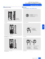
Page 77: ...unctions Design Removable terminals The removable terminal is the innovative connection technique from Siemens for AS Interface SlimLine modules of the S22 5 and S45 Series The complete terminal block can be quickly and easily dismantled and reassembled It is not necessary to dis connect the terminals during this process Note The devices will be converted from 2004 and will be available under the ...

Page 78: ...screw type and Cage Clamp ter minals is fully retained Technical specifications Technical specifications common to all SlimLine modules NSA0_00364 NSA0_00365 NSA0_00366a NSA0_00367a CLICK Operational voltage in accordance with AS Interface specification in V 26 5 to 31 6 Input connection PNP AS Interface certificate Available or under application in the case of new products Approvals UL CSA ship b...

Page 79: ... 0AA2 3RK2 200 0CG02 0AA2 Total current input in mA 50 270 270 Inputs Sensor supply via AS Interface Short circuit and overload withstand capability Short circuit and overload withstand capability Short circuit and overload withstand capability Voltage range in V 20 to 30 20 to 30 20 to 30 Current carrying capacity for sensor supply in mA 200 200 Connection of sensors 2 wire system 2 and 3 wire sy...

Page 80: ... of output PNP transistor Relay PNP transistor Current carrying capacity per output in A DC 12 DC 13 typ 2 2 Maximum summation current per module in A 4 4 Short circuit protection Built in External back up fuse Built in Inductive interference protection free wheeling diode Built in Not applicable Built in Polarity reversal protection Not built in Not applicable Not built in External 24 V DC supply...

Page 81: ... Built in Inductive interference protection free wheeling diode Not applicable Built in Built in Polarity reversal protection Not applicable Built in Built in External 24 V DC supply voltage Not applicable Via screw terminals Terminal 7 Terminal 10 M Via screw terminals Terminal 7 Terminal 10 M Ith 6 AC 15 3 DC 13 24 V 1 DC 13 110 V 0 2 DC 13 230 V 0 1 Watchdog Built in Built in Built in I O confi...

Page 82: ...in mA 1 5 5 1 5 5 1 5 5 Outputs Type of output Electronics Electronics Electronics Current carrying capacity per output in A DC 12 DC 13 typ 1 2 1 Maximum summation current per module in A 4 4 4 Short circuit protection Built in Built in Built in Inductive interference protection free wheeling diode Built in Built in Built in Polarity reversal protection Built in Built in Built in External 24 V DC...

Page 83: ...ummation current per module in A 4 4 Short circuit protection External back up fuse 6 A gL gG Built in No internal fusible link Inductive interference protection free wheeling diode Not applicable Polarity reversal protection Built in Built in External 24 V DC supply voltage Not applicable Terminal 13 L24 Terminal 19 M24 Terminal 13 L24 Terminal 19 M24 Ith 5 AC 15 3 DC 13 24 V 1 DC 13 110 V 0 2 DC...

Page 84: ...reversal protection Built in Built in External 24 V DC supply voltage Sensor supply Terminal 13 U_s Terminal 19 U_s Actuator supply Terminal 14 L Terminals 20 to 24 M Not applicable Ith 5 AC 15 3 DC 13 24 V 1 DC 13 110 V 0 2 DC 13 230 V 0 1 Watchdog Built in Built in I O configuration 7 7 ID ID2 code 0 F 0 F Assignment of data bits Data bit D0 IN1 OUT1 IN1 OUT1 Data bit D1 IN2 OUT2 IN2 OUT2 Data b...

Page 85: ... Electronics Electronics Current carrying capacity per output in A DC 12 DC 13 typ 2 2 Maximum summation current per module in A 4 4 Short circuit protection Built in Built in Inductive interference protection free wheeling diode Built in Built in Polarity reversal protection Built in Built in External 24 V DC supply voltage Terminal 13 L24 Terminal 19 M24 Terminal 13 L24 Terminal 19 M24 Ith AC 15...

Page 86: ...nsistor 1 A 3RK1 100 1CG00 0AA2 SlimLine S45 3RK1 400 1CE00 0AA2 SlimLine S45 module Inputs PNP transistor Type Connection terminals Slave type Inputs Outputs 4 inputs 4 outputs Screw type Standard 2 and 3 wire PNP transistor 1 A 3RK1 400 1CE00 0AA2 PNP transistor 2 A 3RK1 400 1CE01 0AA2 2 and 3 wire floating PNP transistor 1 A floating 3RK1 402 3CE01 0AA2 2 and 3 wire Relay 3RK1 402 3CE00 0AA2 Ca...

Page 87: ...7 N 1 A S i A S i O U T 1 2 3 4 5 6 7 8 9 1 0 1 1 1 2 A d d r e s s i n g s o c k e t L E D s f o r c o m m u n i c a t i o n L E D s f o r i n p u t s 1 4 2 w i r e s e n s o r N 2 N 3 N 4 A S i A D D R I N 3 I N 4 A S i A S i N 1 N 2 N S A 0 _ 0 0 3 2 8 N 1 1 2 3 4 5 6 7 8 9 1 0 1 1 1 2 O U T 3 w i r e s e n s o r A S i 1 4 5 6 2 3 7 1 0 1 1 1 2 8 9 A S i I N 1 I N 2 I N 3 I N 4 1 3 1 6 1 7 1 8 ...

Page 88: ...the master and slave until six AS Interface cycles have elapsed The PLC cycle is not synchronous with the AS Interface cycle For this reason the time that must elapse be fore the output image and input image of the master and PLC are consistent is extended by one AS Interface cycle and one PLC cycle respectively Formula for the cycle time 4 6 5 ms 5 ms 10 ms 180 ms Note 1 The following function bl...

Page 89: ...ty in A DC 12 DC 13 typ 1 2 1 2 Total current of all outputs in A 4 6 4 6 Short circuit protection Built in Inductive interference protection free wheeling diode Built in External voltage supply 24 V DC Built in via terminal screws Built in via Combicon male connector Watchdog Built in I O configuration 7 ID ID2 code 0 F Assignment of data bits Data bit D0 IN1 OUT1 Data bit D1 IN2 OUT2 Data bit D2...

Page 90: ... interference protection free wheeling diode Built in External voltage supply 24 V DC Via screw terminal Via Combicon pin connector Watchdog Built in I O configuration 7 ID ID2 code 0 F Assignment of data bits Data bit D0 IN1 OUT1 Data bit D1 IN2 OUT2 Data bit D2 IN3 OUT3 Data bit D3 IN4 OUT4 AS Interface certificate Yes Approvals UL CSA ship building Degree of protection IP20 Ambient temperature ...

Page 91: ...D3 Data bit D1 Group signal G2 D1 Inputs I 2 1 to I 2 4 D0 to D3 Data bit D2 Group signal G3 D2 Inputs I 3 1 to I 3 4 D0 to D3 Data bit D3 Group signal G4 D3 Inputs I 4 1 to I 4 4 D0 to D3 AS Interface certificate Yes Approvals UL CSA ship building Degree of protection IP20 Ambient temperature in C 25 to 70 Storage temperature in C 40 to 85 Displays Inputs outputs Yellow LED Connection Via screw t...

Page 92: ...istor floating 3RG9 004 0DC00 16 inputs Screw type terminals PNP transistor 3RG9 002 0DE00 Combicon 3RG9 004 0DE00 Accessories Combicon connector set For 4I 4O modules with Combicon connection One set comprises 4 x 5 pin connector for connecting Standard sensors actuators 2 x 4 pin connector for AS Interface and external auxiliary voltage 3RX9 810 0AA00 9 0 7 5 3 7 N S A 0 0 0 7 4 S I E M E N S L ...

Page 93: ...nductive interference protection free wheeling diode Built in External voltage supply DC 24 V Not required all inputs and outputs are sup plied via the AS Interface cable Flat module 4 input 4 outputs 200 mA for all I Os screw type terminals 3RK1 400 0CE00 0AA3 Watchdog Built in I O configuration 7 ID ID2 code F F Assignment of data bits Data bit D0 IN1 OUT1 Data bit D1 IN2 OUT2 Data bit D2 IN3 OU...

Page 94: ...oad proof if UAux is connected to 0 the outputs will be overload and short circuit proof maximum summation current 200 mA If the switching outputs are overloaded the module will not respond to master calls AS Interface communication module for circuit board mounting 3RG9 005 0SA00 The 4I 4O module for PCB mounting can be used to scan up to four mechanical contacts or to activate up to four LEDs wh...

Page 95: ...e module will not respond to master calls AS Interface communication module for circuit board mounting 3RK1200 0CD00 0AA2 1 Note For pad numbering see the Section Dimensional Drawings Via the 4I module for PCB mounting up to four mechanical switches or 3 wire sensors can be connected whereby the in puts are supplied from the AS Interface cable It is mounted easily via a Card edge board to board co...

Page 96: ...to 30 20 to 30 20 to 30 Switching current in mA 3 3 3 Outputs Type of output Electronics Electronics Electronics Electronics Load voltage in V 20 to 30 19 to 30 19 to 30 U Aux 0 8 V Short circuit protection Built in Built in Built in Built in Inductive interference protection free wheeling diode Built in free wheel ing diode External 24 V DC supply voltage Via solder pins Via solder pins Via solde...

Page 97: ...th solder pins protected by a housing 3RK1 400 0CD01 0AA3 Printed circuit board with solder pins for horizontal mounting 3RG9 005 0SA00 Outputs supplied via external auxiliary voltage 24 V PELV Printed circuit board with gold plated direct connector for 30 pole plug connector for easy installation with direct connector 3RK1 400 1CD00 0AA2 4 inputs Printed circuit board with gold plated direct conn...

Page 98: ...e maximum frequency is the required pulse shape To ensure that the counter loads a pulse as valid a low value must be applied to the input for at least 300 µs while a high value must be applied for at least 1 ms This results in a maximum frequency for the counter module independent of the controller of fFCmax 1 1 3 ms 769 Hz for the counter module see diagram nsa00084 In the event of non complianc...

Page 99: ...evel Low High in V 5 10 Input current Low High in mA 2 10 I O configuration 0 ID code F AS Interface certificate Yes Approvals UL CSA ship building Degree of protection IP20 Ambient temperature in C 25 to 70 Storage temperature in C 40 to 85 Displays AS i Green LED on red LED off status O K Green LED off red LED on no data traffic Green LED flashing red LED on null address Green LED off red LED fl...

Page 100: ...iary voltages are not monitored for earth faults by this module Note The earth fault detection module is a passive module with out an IC Therefore it does not require an individual address in the AS Interface network Typical connections N S A 0 _ 0 0 0 9 0 a P E P E 5 k 6 5 k 6 2 4 V 1 A S i 4 A S i 2 3 T 3 R R E S 6 7 L 2 4 8 O K 9 F A U L T 1 2 M 2 4 1 1 M 2 4 1 0 M 2 4 R E S R E S 1 A S i 4 A S...

Page 101: ...arrying capacity 1 DC 12 in A 1 max 2 per module DC 13 in A 500 24 V 2 DC 13 in mA 200 48 V 2 Operating cycles DC 12 2 106 Rated operating voltage range in V 24 to 48 DC Degree of protection IP20 Dimensions H x W x D in mm 102 22 5 92 Rated temperature in C 25 Ambient temperature in C 25 to 70 Storage temperature in C 40 to 85 Addressing The module does not require an individual AS Interface addre...

Page 102: ...No 3RK1 408 8KE00 0AA2 Earth fault detection module with screw terminals 3RK1 408 8KE00 0AA2 with Cage Clamp terminals 3RK1 408 8KG00 0AA2 4 7 45 NSB0_01412 102 5 36 65 86 A C 68 92 Standard terminal Removeable terminal Screw type terminal Spring type terminal A 84 108 C 83 106 A 84 3 107 6 C 81 104 N S B 0 _ 0 1 4 1 3 A B C 7 4 8 6 5 3 6 1 2 0 1 1 0 x 1 5 6 8 4 7 2 2 5 ...

Page 103: ...urrent isn The nominal discharge current is the peak value of a peak cur rent with an 8 20 microsecond waveform for which the overvolt age protection module is rated in accordance with a specific test program With the 8 20 waveform 100 of the value is reached after 8 microseconds and 50 of the value is reached after 20 micro seconds Protection level Up The protection level of an overvoltage protec...

Page 104: ...rve form 8 20 Core to PE in kA 10 10 Core to core in kA 0 5 0 5 Protective level Up at sn Core to PE in kV 1 8 1 8 Core to core in V 100 70 Protective level Up at 1 kV µs Core to PE in V 700 600 Core to core in V 50 40 Mechanical data degree of protection with coupling module IP67 Dimensions H x W x D in mm 80 45 25 Temperature range Ambient temperature in C 25 to 85 Storage temperature in C 40 to...

Page 105: ... just 2 versions the fact that the electronic contact elements in the power section are non wearing current detection used for monitoring the energy connector emergency operation in the event of an overload as well as remote resetting via the AS Interface after overload tripping The ERS compact starter is designed for direct on line starting in reversing mode The electronic overload protection and...

Page 106: ...pact starters indi cate the following device states LED AUX PWR AS Interface STATE 1 NSA0_00322 Status description Control signal applied No auxiliary power Auxiliary power on No power for slave electronics Station address 0 AS Interface communication absent AS Interface communication o k On States Flash ing On On Flash ing Off On Off LED RUN READY FAULT NSA0_00323 OVERLOAD States Status descripti...

Page 107: ... tripping operation Input signal DI0 can be used to check the status of the device Inputs Outputs Input signals Device status Meaning DI0 Ready 0 Device not ready error Manual mode Device has neen switched to manual mode locally switch back to automatic mode using hand held unit Overload short circuit tripping The circuit breaker recloses once a cooling off period has elapsed FAULT signal Defectiv...

Page 108: ... status of the device Inputs Outputs Input signals Device status Meaning DI0 Ready 0 Device not ready error Manual mode Device has been switched to manual mode locally switch back to auto matic mode using hand held unit Tripped signal Rotary coding switch in position Tripping LOCAL Direct shut off Tripping REMOTE Remote shut off or continued operation when pro grammed in the user programme FAULT s...

Page 109: ...driven auxiliary contacts and separate inputs Via LED at the housing Auxiliary voltage applied AS Interface communication OK AS Interface communication faulty Station address 0 module not addressed Via LED at the hand held terminal ON or clockwise rotation or anti clockwise rotation Main circuit Rated operational voltage 500 V AC to DIN VDE 0106 Part 101 AC 600 V to CSA and UL Safety separation be...

Page 110: ...ct starter Electromechanical reversing starter with two spare digital inputs 3RK1 322 S02 1AA Three phase motor 4 pole at 400 V AC standard output P Setting range of the overcurrent release kW A 0 06 0 14 to 0 20 0 B 0 06 0 18 to 0 25 0 C 0 09 0 22 to 0 32 0 D 0 10 0 28 to 0 40 0 E 0 12 0 35 to 0 50 0 F 0 18 0 45 to 0 63 0 G 0 21 0 55 to 0 80 0 H 0 25 0 70 to 1 0 0 J 0 37 0 9 to 1 25 0 K 0 55 1 1 ...

Page 111: ...02 0CB00 Connector set for power loop through connection 9 pole Comprising 1 connector housing with Pg 16 cable gland 1 male insert 9 pole 6 male contacts Suitable for cable 4 2 5 mm2 6 2 5 mm2 3RK1 902 0CC00 Suitable for cable 4 4 mm2 6 4 mm2 3RK1 902 0CD00 Connector set for motor connection 1 5 mm2 9 pole Comprising 1 connector housing with Pg 16 cable gland 1 male insert 9 pole 8 male contacts ...

Page 112: ...l i n p u t P i n 3 S u p p l y L P i n 4 S i g n a l i n p u t P i n 5 P E 6 1 4 8 3 5 2 7 L 2 L 3 L 1 X 2 6 1 4 8 3 5 2 7 L 2 L 3 L 1 X 1 8 3 5 6 1 4 2 7 L 2 L 3 L 1 X 3 N S A 0 _ 0 0 3 4 9 P i n 1 P i n 2 P i n 3 P i n 4 P i n 5 P i n 6 P i n 7 P i n 8 C e n t e r n o t a s s i g n e d P h a s e L 2 s p a r e G N D f o r b r a k e o p t i o n a l D C 2 4 V f o r b r a k e o p t i o n a l P h a ...

Page 113: ... B r a k e w i t h c o a s t i n g o f f o n I n p u t 1 I n p u t 2 O u t p u t 1 B u t t o n 1 m a n u a l o p e r a t i o n O u t p u t 2 Q u i c k s t o p f o r o u t p u t 2 o n o f f Q u i c k s t o p f o r o u t p u t 1 o n o f f B u t t o n 2 m a n u a l o p e r a t i o n A d d r e s s S e n s o r 1 S e n s o r 2 S e n s o r 3 S e n s o r 4 S e n s o r s i g n a l S e n s o r s i g n a l S...

Page 114: ... time for DC motor in ms 80 Max motor start up current internally limited in A 4 5 Outputs Type of output Electronics Nominal load rating per output in A 3 Tu 55 C 1 x 3 Tu 55 C 2 x 2 Tu 55 C 2 5 Tu 55 C Max total current in A 4 Voltage drop without incoming line in V 0 6 1 2 Short circuit protection Built in Inductive interference protection free wheeling diode Built in Watchdog Built in I O conf...

Page 115: ...4 3RK1 400 1MQ03 0AA4 Design Order No 3RK1 400 1MQ01 0AA4 Single direct on line starter 1 4 inputs 1 output Quickstop function 3RK1 400 1NQ01 0AA4 Dual direct on line starter 1 4 inputs 2 outputs Quickstop function 3RK1 400 1MQ01 0AA4 Single reversing starter 1 4 inputs 1 output Quickstop function 3RK1 400 1MQ03 0AA4 29 NSA0_00113a 152 60 3RK1901 0CA00 mounting plate 29 NSA0_00114a 152 60 3RK1901 ...

Page 116: ...ation displacement method for AS Interface Han Q8 for the power supply Han 10e for motor connection The starters can be connected using T pieces for data and power to prevent interruption Selection and Ordering data Design Order No Fieldbus interface Switching function Motor protection Adjustment performance range Brake output PROFIBUS DP Mechanical Thermistor 0 3 to 9 A 4 kW No 3RK1 303 2AS51 1AA...

Page 117: ...er connector for up to 16 A The complete feeder units are available with AS Interface load feeder modules with electronic outputs for an auxiliary voltage of DC 24 V Load feeder units of this kind are used for instance to control standard three phase motors The load feeders can be installed in central switchgear cubicles or in distributed onsite switch gear boxes They are particularly suitable for...

Page 118: ...e length between IN and an input in m 0 4 Outputs External supply voltage for outputs in V triggering of the contactor coils via auxiliary power 24 DC Max 230 AC Current carrying capacity Ie in A 0 5 DC 13 DC 14 3 AC 15 0 1 DC 13 at 220 V Summation current thermal Ith in A 2 3 Polarity reversal protection Built in Not required Short circuit protection Built in No Inductive interference protection ...

Page 119: ...0 230 AC 3 3RK1 402 3KG02 0AA1 3 inputs 2 relay outputs 3RK1 402 3LG02 0AA1 Accessories 4 Manual for AS Interface load feeder module German English 3RK1 701 2GB00 0AA0 Italian French 3RK1 701 2HB00 0AA0 Carrier with mounted power connector coupling Carrier for AS Interface load feeder module With PE and N conductor connection for mounting on busbar adapter with 40 mm rail center line spacing Power...

Page 120: ...eeder module with 4 inputs and 2 outputs or 3 inputs and 2 outputs as reversing starter When using SIRIUS contactors we recommend that the posi tively driven auxiliary NC contacts are used for feedback of the switching status I N 1 N S A 0 0 0 9 7 I N 2 M N X 3 1 X 3 2 X 3 3 X 4 1 X 4 2 I N O U T 1 Q 1 K 1 K 1 N S A 0 0 0 9 5 I N 4 M N X 3 3 X 3 4 X 3 5 X 3 6 X 3 7 X 3 2 X 3 8 I N 3 I N 1 I N 2 X ...

Page 121: ...ding throughout the drive Reduction of the loading on the power supply system Selection and Ordering data 1 For mounting the AS Interface load feeder module on the standard rail adaptor a carrier plug connector and power connector set are also required Additional information is available in the Internet under http www siemens de sanftstarter Design Order No SIRIUS Soft Starter with AS Interface lo...

Page 122: ... is not in cluded in the scope of supply Connection is via the AS Interface shaped cable using the insu lation piercing method Addressing is via the AS Interface connections or via the built in addressing socket Selection and Ordering data 1 EMERGENCY STOP actuator is not included in the scope of supply For further details on the EMERGENCY STOP actuator see the Section Pushbutton Units and Indicat...

Page 123: ...tion and Ordering data N S D 0 _ 0 0 0 5 8 T e r m i n a l S h a p e d A S I n t e r f a c e c a b l e F l e x i b l e l e a d a p p r o x 2 0 c m l o n g E n c l o s u r e p a r t E n c l o s u r e c o v e r P C B Design Order No AS Interface enclosure with standard arrangement of components Arrangement of components A B C Code letters for command points Number of com mand points A EMERGENCY STOP...

Page 124: ...is mounted above or to the right The AS Interface cable is then looped through to supply the non safe command devices of the enclosure EMERGENCY STOP via an F adaptor is only possible for enclosures for three four or six command points The following methods can be used for connecting the AS Inter face cable Terminal for shaped AS Interface cable Contact is made with the cable using the insulation ...

Page 125: ...ule 3SF5 874 4AZ KOY Equipment according to order supplement for AS Interface front panel module For form to complete order supplement see section Options Options To order customized AS Interface solutions for SIGNUM 3SB3 control devices please fill out the corresponding enclosed order form and enclose it with the order Enter the desired options into the order form such as type of actuating elemen...

Page 126: ...le gland drill hole is not pressed out r terminal for by passed AS Interface cable r metric cable gland for inserted AS Interface cable r metric cable gland for inserted round cable r M12 socket for free input or output r AS Interface F adaptor only for housings with EMERGENCY STOP 7 Terminal on top resp on the left r no cable gland drill hole is not pressed out r terminal for by passed AS Interfa...

Page 127: ...molded plastic r round metal 3 Name plates r without r with name plate including legend plate 12 5 mm 27 mm glued in r with name plate including legend plate 27 mm 27 mm glued in 4 Configuration Top view of front side of switchboard 5 Lamps r incandescent lamp 24V if no option is marked an incandescent lamp 24 V will be used r incandescent lamp 30V r super bright LED LED color is same as the color...

Page 128: ...Pushbutton with protruding mounting ring castellated DFZ BK DFZ RD DFZ YE DFZ GN DFZ BU DFZ WH Pressure switch with flat pushbutton DS BK DS RD DS YE DS GN DS BU DS WH Illuminated pressure switch with flat pushbutton DLS RD DL YE DLS GN DLS BU DLS WH DLS CL Mushroom head pushbutton Ø 30 mm 2 P30 BK P30 RD P30 YE P30 GN Illuminated mushroom head pushbutton Ø 30 mm 2 PL30 YE PL30 GN PL30 WH Mushroom...

Page 129: ...D K1 GN K1 WH illuminated BK1 RD BK1 YE BK1 GN BK1 BU BK1 CL Switching sequence O I pushbutton control with resetting from the right not illuminated K2 BK K2 RD K2 GN K2 WH illuminated BK2 RD BK2 YE BK2 GN BK2 BU BK2 CL Switching sequence I O II latching not illuminated K4 BK K4 RD K4 GN K4 WH illuminated BK4 RD BK4 YE BK4 GN BK4 BU BK4 CL Switching sequence I O II pushbutton con trol with resetti...

Page 130: ... Z J 1AE Type BKS Lock no S1 BKS 1A BKS 1E BKS 1AE Lock no E1 for VW BKS A 1A BKS A 1AE Lock no E2 for VW BKS E 1A BKS E 1AE Lock no E7 for VW BKS C 1A BKS C 1AE Lock no E9 for VW BKS B 1A BKS B 1AE Type O M R black Lock no 73034 OMR BK 1A OMR BK 1E OMR BK 1AE Switching sequence O I pushbutton con trol with resetting from the right Type RONIS flat Lock no SB30 RSB 2A Type CES Lock no SSG 10 CES 2A...

Page 131: ...SG 10 CES 5A Type IKON Lock no 360012 K1 Z J 5A Type BKS Lock no S1 BKS 5A Type O M R black Lock no 73034 OMR BK 5A Switching sequence I O II latches on the right pushbutton control on the left with resetting from the left Type RONIS flat Lock no SB30 RSB 6A RSB 6D RSB 6AD Type CES Lock no SSG 10 CES 6A CES 6D CES 6AD Type IKON Lock no 360012 K1 Z J 6A Z J 6D Z J 6AD Type BKS Lock no S1 BKS 6A BKS...

Page 132: ... 2004 6 132 AS Interface Slaves AS Interface customized enclosures and front panel modules SIGNUM pushbuttons and indicator lights 6 Dimensional drawings AS Interface front panel module 1 2 0 5 2 4 5 N S D 0 0 2 3 6 ...

Page 133: ...insulated Addresses 1 address per display With AS Interface After the 15th addressing the display keeps the last address Housing Bay housing to DIN metal Mounting Screw bracket to DIN Degree of protection IP54 to the front with AS Interface IP65 Ambient temperature During operation in C 0 to 50 During storage in C 25 to 70 EMC Acc to the specifications of the 89 336 EWG or EMVG guideline Emitted i...

Page 134: ...e interface provides four inputs and four outputs for the sys tem These I Os however are not actually implemented in hard ware they only exist virtually via the interface on the bus Technical specifications Selection and Ordering data Supply voltage in V 24 V DC Inputs outputs 4 4 virtual inputs outputs Bus connection AS Interface according to specification Ambient temperature in C 0 to 55 Degree ...

Page 135: ...ge the very compact combination power supply unit with 1 x 30 V DC and 1 x 24 V DC can be used If so called double masters are used the dual power supply unit with 2 x 30 V can be used Performance characteristics high efficiency low residual ripple short circuit proof and stable at no load overvoltage protection at input small dimensions low weight simple and fast assembly All AS Interface power s...

Page 136: ...Current rating a Rated in A 2 4 power boost 2 8 4 power boost 4 5 DC 3 3 power boost DC 4 Efficiency power loss Efficiency at UaRated aRated in Approx 85 Power loss at UaRated aRated in W Approx 10 Approx 18 Approx 15 Protective and monitoring functions Output overvoltage protection No Current limitation in A 2 8 5 Short circuit protection Yes Safety Primary secondary isolation SELV to EN 60 950 S...

Page 137: ...ional display Green LED Current rating a Rated in A 2x4 4 5 Efficiency power loss Efficiency at UaRated aRated in Approx 85 Power loss at UaRated aRated in W Approx 36 Protective and monitoring functions Overvoltage protection of outputs No Current limitation in A 4 power boost 4 5 4 5 power boost 4 5 5 5 Short circuit protection Yes Safety Primary secondary isolation SELV to EN 60 950 SELV to EN ...

Page 138: ...nd monitoring functions Overvoltage protection of outputs Yes No Current limitation in A From approx 7 4 2 8 Short circuit protection Stabilized current characteristic approx 7 4 A Yes Safety Primary secondary isolation SELV to EN 60 950 Safety class EN 60 950 IEC 950 Class I to IEC 536 I Degree of protection IP20 to EN 60 529 IP20 Approvals CE UL cUL CE UL CSA in preparation EMC Emitted interfere...

Page 139: ...ingle output 2 4 A 115 230 V AC selectable 3RX9 307 0AA00 4O 3RX9 307 1AA00 3 3 A can be connected in parallel 230 400 V AC repositionable 4FD5 213 0AA10 1A 7 A 120 230 V AC 6EP1 354 1AL01 3RX9 310 0AA00 Single output with integrated earth fault detection 2 4 A 115 230 V AC selectable 3RX9 310 0AA00 3RX9 305 1AA00 Dual output 4 A 4 A 3RX9 305 1AA00 Combi output 1 x 24 V DC 1 x 30 V DC 5 A 24 V 4 A...

Page 140: ...0 1 2 0 NSA00121 135 107 75 NSA00122 135 107 150 A B C D E F G H 1 0 5 1 9 0 1 N S A 0 _ 0 0 1 2 3 5 4 6 7 1 3 5 1 m a x 1 1 0 A S i A S i _ _ _ S u i t a b l e f o r m o u n t i n g o n t o E N 5 0 0 2 2 3 5 x s t a n d a r d m o u n t i n g r a i l F u s e 2 5 0 V 2 A L E D d i s p l a y N S A 0 0 1 2 4 S I T O P S I E M E N S p o w e r A S I 6 E P 1 3 5 4 1 A L 0 1 O K V O L T A G E S E L E C T...

Page 141: ...s Efficiency at Ua rated Ia rated in Approx 85 81 Power loss at Ua rated Ia rated in W Approx 10 17 Protection and monitoring functions Output overvoltage protection No Current limitation in A 2 8 From approx 2 9 Short circuit protection Yes Stabilized current approx 2 9 A Safety Primary secondary isolation Yes SELV to EN 60 950 Yes SELV to EN 60 950 Safety class Class I to IEC 536 Class I to IEC ...

Page 142: ...A B C D E F G H 1 0 5 1 N S A 0 _ 0 0 1 1 7 1 1 0 1 5 4 6 7 1 4 8 2 1 4 5 1 A S i A S I n t e r f a c e P o w e r o n A S i A S i A S I n t e r f a c e c o n n e c t i o n M a i n s c o n n e c t i o n S u i t a b l e f o r m o u n t i n g o n t o E N 5 0 0 2 2 3 5 x s t a n d a r d m o u n t i n g r a i l 1 2 3 4 5 6 N S A 0 _ 0 0 1 1 8 1 P E 2 P 2 4 3 M 2 4 I N P U T 2 4 V 4 2 A P 3 0 M 3 0 O U ...

Page 143: ...face data and a 24 V DC auxiliary supply voltage can be connected for the sensors e g BERO proximity switches and actuators e g LEDs via the yellow AS Interface cable For 24 V DC actuators e g solenoid valves that have a high current requirement or that are integrated into EMERGENCY STOP circuits the black AS Interface cable must be used Technical specifications EPDM rubber TPE special PVC compoun...

Page 144: ... No UL 758 AWM UL 758 AWM UL 13 Class 2 UL 444 CMG No CSA approval No C22 2 No 210 2 AWM C22 2 No 214 02 No Certificate Überwachtes Gutachten ÜG by VDE No No No VDE reg No 9971 300 V 500 V Stationary 40 to 70 C Transport 25 to 70 C Moving 15 to 70 C Approved for marine and offshore applications up to 300 V 500 V Germanischer Lloyd Lloyds Register of Shipping ABS Europe LTD Bureau Veritas Det Norsk...

Page 145: ...mes in the event of a fault with separate display of the correct AS Interface voltage for each end Extenders Expansion of the range of applications and greater freedom in plant design by extending the AS Interface segment When the extender is used the master can be located at a distance of up to 100 m and a power supply is not required at the master end Application The repeater is used to extend t...

Page 146: ...erface segment itself Slaves can be used only on side turned away from master AS Interface power supply only required on side turned away from master No electrical isolation of the two AS Interface shaped cable strands Indication of correct AS Interface voltage Installed in user module housing with FK E coupling module as bottom part Extender connection Ordering data Order No Power section Repeate...

Page 147: ...ode according to AS Interface Version 2 1 Programming ID code 1 Function testing of slaves Read inputs and wire outputs of dig ital or anlog slaves AS Interface test Measurement of voltage measuring range 0 to 35 V and current consumption measuring range 0 to 100 mA of the AS Interface bus Storage Complete plant configurations can be saved profiles of all slaves also extension in accordance with A...

Page 148: ...ostics unit For active AS Interface modules intelligent sensors and actuators According to AS Interface Version 2 1 Including expanded addressing mode Scope of supply One addressing unit One operator s guide English German French Italian Spanish One addressing cable 1 5 m with jack plug 3RK1 904 2AB01 Accessories FK E coupling module with integrated addressing socket 1 For addressing application m...

Page 149: ... made possible by the intuitive display in statistics mode Test reports provide proof of the state and quality of the instal lation for servicing and approval Reports facilitate remote diagnostics by the technical assis tance department Advanced trigger functions permit exact analysis Process data can be monitored online Function Connection As a passive station the AS Interface Analyzer listens to...

Page 150: ...ower supply OK Power RS 232 interface in use Test mode Statistics mode Telegram memory 256 000 AS Interface telegrams Rated operating current in mA Approx 70 from AS Interface Rated insulation voltage in V 500 EMC According to EN50081 2 EN61000 6 2 Ambient temperature in C 0 to 55 Storage temperature in C 25 to 70 Requirements IBM compatible PC 80486 or better Operating system Windows 95 98 Window...

Page 151: ...ns ten seals 3RX9 805 0AA00 3RX9 806 0AA00 Cable adapter for flat cable Pg connection of AS Interface cable to Pg cable glands with insulation piercing method Continues via standard cable For Pg 9 screwed gland 3RX9 808 0AA00 For Pg 11 screwed gland 3RX9 806 0AA00 For Pg 13 5 screwed gland 3RX9 807 0AA00 Continues via pins For Pg 9 screwed gland 3RX9 818 0AA00 For Pg 11 screwed gland 3RX9 816 0AA0...

Page 152: ...refe rence code CD Z 735 and your address or on the Internet under the heading Documentation Additional information is available in the Internet under http www siemens de as interface Design Order No 3RX9 800 0AA00 AS Interface cover For FK and Pg coupling modules EMS electromechanical interface 3RX9 800 0AA00 3RG9 001 0AD00 4 way distributor Passive without LED 3RG9 001 0AD00 Brochures Documentat...

Reviews: