UM353-1B
Function Blocks
April 2012
3-1
3.0 FUNCTION BLOCKS
This section contains a detailed description of each function block (FB) available for configuration. Each function
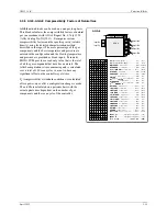
block description is supplemented by: (1) a drawing of the block showing data inputs and outputs and control lines,
(2) a block parameter table. Most blocks are further described by a block diagram that shows the block’s circuitry
in a simplified or equivalent circuit form.
NOTES
This User’s Manual includes the functionality provided by MPU Controller Board
Design Level “B” and firmware Version 4.0.
Keep your controller firmware current by subscribing to updates. The latest firmware
version will often provide performance options (e.g. additional function blocks,
parameter selections) not available in an earlier version.
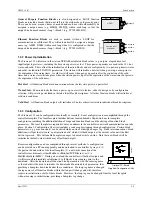
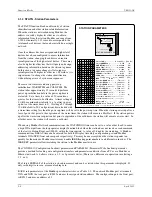
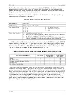
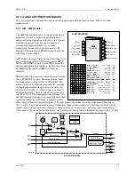
Function blocks have three types of inputs/outputs: digital, analog, and special data structure.
1.
Arrows with dark shading and white letters are digital (outputs are displayed as 0 and 1 in the VIEW mode
when using the local faceplate). Digital outputs are typically used to designate function block status, logical
outputs, and on/off function block outputs. Some examples are:
•
Function block status: E/I status (IS, ES, SI), A/M status (AS, NA, MS, ES, SS), and Quality Status (QS)
•
Logical Outputs: AND (01), OR (01), NOR (01), or NOT (01)
•
On/Off function blocks: One Shot Timer (01), Retentive On Timer (01), Rising Edge Trigger (01), Alarms
(A1, A2, A3, and A4), and Comparator (01)
2.
Arrows with medium shading and black letters are analog. Internally they are REAL floating point numbers
and outputs of these types will be displayed in the VIEW mode when using the local faceplate with the decimal
point located to allow greatest resolution between 0.00000 and 999999 or -0.0000 and -99999. Numbers
outside this resolution will blink.
Analog outputs are typically output (01) for analog I/O blocks and math functions. Analog outputs may also be
specific to a particular function block such as the Analog Output (AO), Step Number (SN), Step Time (ST),
Remaining Time (RT), and Current Recipe (CR) outputs of the Program Sequencer.
3.
Arrows with medium shading and black letters but with a white tip are special data structures for range scaling
information and will not be displayed in the VIEW mode). Range scaling information is used when there is a
conversion of units within a function block, for example, the Alarm block scales the alarm limits into process
engineering units when the range pointer is configured to the process analog input block. If unconfigured the
units default to 0-100%. The output range (OR), typically used on analog input function blocks, includes MIN
and MAX SCALE, the DPP (Decimal Point Position), and the ENGUNITS (Engineering Units).
The output range is connected to the Range Pointer (input R) of functions blocks requiring scaling other than
the default 0-100. For example, an Analog input block could be scaled 0-5000 psig with output (01) connected
to the AOUT input (S) and the AIN (OR) connected to the AOUT input (R). The Analog output would then
output 4 mA at a minscale of 0 psig and 20 mA at a maxscale of 5000 psig. In contrast, if AOUT input (R)
were left unconfigured the output would equal 4 mA at a minscale of 0 psig, 20 mA at a maxscale of 100 psig
and over ranged for any input over 100 psig.
Some users may prefer to use normalized 0-1 analog inputs for math calculations and scale outputs for display
only; in this case, the Scaler function block may be used to provide an output range (OR) for the ODC
(Operator display block).
Note how the range pointers are used in the following Factory Configured Options (FCOs). FCOs are described
in detail in Section 4 Factory Configured Options.
•
FCO101 Single Loop Controller – The process output range AIN1 (OR) is connected to the range pointer
of the SETPT block, the PID block, the ALARM block and the process variable range of the ODC block.
As a result these blocks will be automatically rescaled when the minscale and the maxscale or the
Summary of Contents for 353
Page 12: ...Contents UM353 1B x April 2012 ...
Page 22: ...Introduction UM353 1B April 2012 1 10 ...
Page 30: ...Configuration Overview UM353 1B April 2012 2 8 ...
Page 122: ...Function Blocks UM353 1B April 2012 3 92 ...
Page 168: ...Data Mapping UM353 1B April 2012 6 28 ...
Page 204: ...Controller and System Test UM353 1B April 2012 9 8 ...
Page 222: ...Calibration UM353 1B April 2012 11 4 ...
Page 226: ...Circuit Description UM353 1B April 2012 12 4 ...
Page 238: ...Model Designation and Specifications UM353 1B April 2012 13 12 EC Declaration of Conformity ...
Page 240: ...Model Designation and Specifications UM353 1B April 2012 13 14 ...
Page 244: ...Abbreviations And Acronyms UM353 1B 14 4 April 2012 ...

