background image

Function Blocks 

UM353-1B 


April 

2012 

3-52 

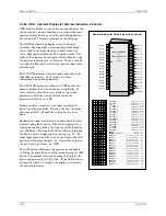
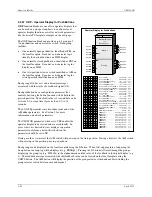
3.2.54  ODA - Operator Display for Analog Indication & Alarming 

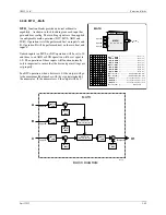
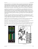
ODA blocks are one of five operator displays that are used on a one 
per loop basis to configure the local operator display functions and 
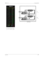
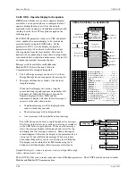
network parameters.  See the i|ware PC faceplate on the next page. 
 
The block will display up to four process variables P1 to P4 in both 
analog bargraph and digital form.  Two alarms are associated with 
each process variable. They can be configured as HI or LO alarms.  
Each alarm function has associated block outputs that are high (1) 
when the alarm is active.  Output LE is high (1) when a loop event is 
active. Output SE is high when a station error is active.  LOOP # 
parameters are used to index reads and writes to Modbus network 
parameters.  See Section 5 for network parameters. 
 
The VIEW OD parameter, when set to YES, enables the operator 
display to be viewed and accessed locally.  In cases where it is desired 
to view display or operation parameters only from a network 
workstation, the parameter should be set to NO. 
 
Range pointers (i.e. R1 to R4) for all four process inputs must be 
configured to define the range of each variable input (i.e. P1 to P4).  If 
these parameters are not configured, the bargraphs will be scaled using 
the engineering range of 0.00 to 100.00. This information also defines 
the scaling of the loop information provided to a remote workstation 
over the network (i.e. Modbus or Modbus/TCP Ethernet). 
 
Each process variable can be displayed on the local faceplate using the 
D button. When first stepping into a loop using the Loop button, the 
loop tag will be displayed (e.g. AnDisp1). However, if there is a point 
within the loop that has an unacknowledged alarm, that point will be 
displayed alternating between the point tag and the alarm condition 
(e.g. PI693/3B LO). Press the D button to scroll through the analog 
points displaying the point tag (e.g. TI712) in the alphanumeric and 
the value of the point in the digital display (e.g. 348.47).  Press the 
UNITS button to display the units of the point.  Press the Loop tag to 
return to displaying the loop tag. 
 

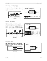
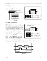
Alarm Types 


HI

 compares the process input with the limit setting and trips the 

alarm status high (1) when the process is equal to or higher than the 
limit setting. The alarm status will clear (0) when the process is less 
than the limit setting minus the deadband. 
 

LO

 compares the process input with the limit setting and trips the 

alarm status high (1) when the process is equal to or less than the limit 
setting. The alarm status will clear (0) when the process is greater than 
the limit setting plus the deadband. 

 
OR

 compares the process input with the range limits referenced by the 

range pointer parameter. It will trip the alarm status high (1) when the 
process is equal to or greater than the high limit, or equal to or less 
than the low limit. The alarm status will clear (0) when the process is 
less than the high limit minus the deadband or greater than the low 
limit plus the deadband. 
 

P

rocess 

1

Operator Display for Analog indication & alarming

B1

ODA

P1

R2

R3

Alarm 

B

 P

1

INPUT P4 

(H)


.........................

 loop tag.block tag.output      (null)

INPUT P3


(H)

 .........................

 loop tag.block tag.output      (null)

INPUT P2


(H)

 .........................

 loop tag.block tag.output      (null)

INPUT P1


(H)

 .........................

 loop tag.block tag.output      (null)

R4

LE

L

oop

 E

vent

A1

P

rocess 

1 - R

an

G

e

 P

oin

T

e

R


(S)

 ......... 

loop tag.block tag      (null)

P

G

R

P T R

G

R

P T R

P

I N P U T
I
I
I

N
N
N

P
P
P

U
U
U

T
T
T

P

P

G

R

P T R

P

G

R

P T R

Operator Display

for

Analog Indication
              &
       Alarming

WD

W

atch 

D

og

P2

Process 

R

ange 

1

R1

P3

P4

O D

W

I E

V

VIEW


O

perator 

D

isplay 

(H) 

......................... NO/YES   

 (YES)

SE

S

tation

 E

rror

Process 

R

ange 

2

P

rocess 

2

Process 

R

ange 

3

P

rocess 

3

Process 

R

ange 

4

P

rocess 

4

1
2
3
4

1

P 2
P 3
P 4

P

rocess 

2 - R

an

G

e

 P

oin

T

e

R


(S)

 ......... 

loop tag.block tag      (null)

P

rocess 

3 - R

an

G

e

 P

oin

T

e

R


(S)

 ......... 

loop tag.block tag      (null)

P

rocess 

4 - R

an

G

e

 P

oin

T

e

R


(S)

 ......... 

loop tag.block tag      (null)

1 A

L I M I T

1 B

L I M I T

Process 

1

 Alarm  

A LIMIT

(S)

 ............................. Real


 (110.0)

Process 

1

 Alarm  

B LIMIT

(S)

 ............................. Real


 (-10.0)

2 A

L I M I T

2 B

L I M I T

Process 

2

 Alarm  

A


LIMIT

(S)

 ............................. Real


 (110.0)

Process 

2

 Alarm  

B LIMIT

(S)

 ............................. Real


 (-10.0)

3 A

L I M I T

3 B

L I M I T

Process 

3

 Alarm  

A LIMIT

(S)

 ............................. Real


 (110.0)

Process 

3

 Alarm  

B LIMIT

(S)

 ............................. Real


 (-10.0)

4 A

L I M I T

4 B

L I M I T

Process 

4

 Alarm  

A LIMIT

(S)

 ............................. Real


 (110.0)

Process 

4

 Alarm  

B LIMIT

(S)

 ............................. Real


 (-10.0)

1 A

D B A N D

Process 

1

 Alarm  

A D

ead

BAND 

(S)

 ..... 

0.1/0.5/1.0/5.0%      (0.5)

1 B

D B A N D

Process 

1

 Alarm  

B D

ead

BAND 

(S)

 .....

 0.1/0.5/1.0/5.0%


 (0.5)

2 A

D B A N D

Process 

2

 Alarm  

A D

ead

BAND 

(S)

 ..... 

0.1/0.5/1.0/5.0%


 (0.5)

2 B

D B A N D

Process 

2

 Alarm  

B D

ead

BAND 

(S)

 ..... 

0.1/0.5/1.0/5.0%


 (0.5)

3 A

D B A N D

Process 

Alarm  

A D

ead

BAND 

(S)

 ..... 

0.1/0.5/1.0/5.0%


 (0.5)

3 B

D B A N D

Process 

3

 Alarm  

B D

ead

BAND 

(S)

 ..... 

0.1/0.5/1.0/5.0%


 (0.5)

4 A

D B A N D

Process 

4

 Alarm  

A D

ead

BAND 

(S)

 ..... 

0.1/0.5/1.0/5.0%


 (0.5)

4 A

D B A N D

Process 

4

 Alarm  

B D

ead

BAND 

(S)

 ..... 

0.1/0.5/1.0/5.0%


 (0.5)

1 A

P U

E N

Process 

1

 Alarm  

A P

ower

 U

p

 EN

abled 

(S)

 .NO/YES


 (YES)

1 B

P U

E N

Process 

1

 Alarm  

B P

ower 

U

EN

abled 

(S)

 .NO/YES


 (YES)

2 A

P U

E N

Process 

2

 Alarm  

A P

ower

 U

p

 EN

abled 

(S)

 .NO/YES


 (YES)

2 B

P U

E N

Process 

Alarm  

B P

ower 

U

EN

abled 

(S)

 .NO/YES


 (YES)

3 A

P U

E N

Process 

3

 Alarm  

A P

ower

 U

p

 EN

abled 

(S)

 .NO/YES


 (YES)

3 B

P U

E N

Process 

3

 Alarm  

B P

ower 

U

p

 EN

abled 

(S)

 .NO/YES


 (YES)

4 A

P U

E N

Process 

4

 Alarm  

A P

ower

 U

p

 EN

abled 

(S)

 .NO/YES


 (YES)

4 B

P U

E N

Process 

4

 Alarm  

B P

ower 

U

p

 EN

abled 

(S)

 .NO/YES


 (YES)

1 A

P R

O R

Process 

1

 Alarm  

A PRIOR

ity 

(S)

 ................1/2/3/4/5


 (3)

I

1 B

P R

O R

Process 

1

 Alarm  

B PRIOR

ity 

(S)

 ................1/2/3/4/5


 (3)

I

2 A

P R

O R

Process 

2

 Alarm  

A PRIOR

ity 

(S)

 ................1/2/3/4/5


 (3)

I

2 B

P R

O R

Process 

2

 Alarm  

B PRIOR

ity 

(S)

 ................1/2/3/4/5


 (3)

I

3 A

P R

O R

Process 

3

 Alarm  

A PRIOR

ity 

(S)

 ................1/2/3/4/5


 (3)

I

3 B

P R

O R

Process 

3

 Alarm  

B PRIOR

ity 

(S)

 ................1/2/3/4/5


 (3)

I

4 A

P R

O R

Process 

4

 Alarm  

A PRIOR

ity 

(S)

 ................1/2/3/4/5


 (3)

I

4 B

P R

O R

Process 

4

 Alarm  

B PRIOR

ity 

(S)

 ................1/2/3/4/5


 (3)

I

1 A

T

P E

Process 

1

 Alarm 

 A TYPE


(S)

 .............none/HI/LO/or


 (HI)

Y

1 B

T

P E

Process 

1

 Alarm 

 B TYPE


(S)

 .............none/HI/LO/or


 (LO)

Y

2 A

T

P E

Process 

2

 Alarm 

 A TYPE


(S)

 .............none/HI/LO/or


 (HI)

Y

2 B

T

P E

Process 

2

 Alarm 

 B TYPE


(S)

 .............none/HI/LO/or


 (LO)

Y

3 A

T

P E

Process 

3

 Alarm 

 A TYPE


(S)

 .............none/HI/LO/or


 (HI)

Y

3 B

T

P E

Process 

3

 Alarm 

 B TYPE


(S)

 .............none/HI/LO/or


 (LO)

Y

4 A

T

P E

Process 

4

 Alarm 

 A TYPE


(S)

 .............none/HI/LO/or


 (HI)

Y

4 B

T

P E

Process 

4

 Alarm 

 B TYPE


(S)

 .............none/HI/LO/or


 (LO)

Y

1 A

D

I N

Proc 

1

 Alarm 

A DeLay IN


(S)

 ..... 0/.4/1/2/5/15/30/60


 (0)

L

1 B

D

I N

Proc 

1

 Alarm 

B DeLay IN


(S)

 ..... 0/.4/1/2/5/15/30/60


 (0)

L

2 A

D

I N

Proc 

2

 Alarm 

A DeLay IN


(S)

 ..... 0/.4/1/2/5/15/30/60


 (0)

L

2 B

D

I N

Proc 

2

 Alarm

 B DeLay IN


(S)

 ..... 0/.4/1/2/5/15/30/60


 (0)

L

3 A

D

I N

Proc 

3

 Alarm

 A DeLay IN


(S)

 ..... 0/.4/1/2/5/15/30/60


 (0)

L

3 B

D

I N

Proc 

3

 Alarm

 B DeLay IN


(S)

 ..... 0/.4/1/2/5/15/30/60


 (0)

L

4 A

D

I N

Proc 

4

 Alarm

 A DeLay IN


(S)

 ..... 0/.4/1/2/5/15/30/60


 (0)

L

4 B

D

I N

Proc 

4

 Alarm

 B DeLay IN


(S)

 ..... 0/.4/1/2/5/15/30/60


 (0)

L

1 A

D

O

T

Proc 

1

 Alarm

 A DeLay OUT


(S)

 . 0/.4/1/2/5/15/30/60


 (0)

L

U

1 B

D

O

T

Proc 

1

 Alarm

 B DeLay OUT


(S)

 . 0/.4/1/2/5/15/30/60


 (0)

L

U

2 A

D

O

T

Proc 

2

 Alarm

 A DeLay OUT


(S)

 . 0/.4/1/2/5/15/30/60


 (0)

L

U

2 B

D

O

T

Proc 

2

 Alarm

 B DeLay OUT


(S)

 . 0/.4/1/2/5/15/30/60


 (0)

L

U

3 A

D

O

T

Proc 

3

 Alarm

 A DeLay OUT


(S)

 . 0/.4/1/2/5/15/30/60


 (0)

L

U

3 B

D

O

T

Proc 

3

 Alarm

 B DeLay OUT


(S)

 . 0/.4/1/2/5/15/30/60


 (0)

L

U

4 A

D

O

T

Proc 

4

 Alarm

 A DeLay OUT


(S)

 . 0/.4/1/2/5/15/30/60


 (0)

L

U

4 B

D

O

T

Proc 

4

 Alarm

 B DeLay OUT


(S)

 . 0/.4/1/2/5/15/30/60


 (0)

L

U

1 A

R

B

K

Process 

Alarm

 A R

in

G B

a

CK


(S)

 ............ NO/YES


 (NO)

G

C

1 B

R

B

K

Process 

Alarm

 B R

in

G B

a

CK


(S)

 ............ NO/YES


 (NO)

G

C

2 A

R

B

K

Process 

Alarm

 A R

in

G B

a

CK


(S)

 ............ NO/YES


 (NO)

G

C

2 B

R

B

K

Process 

2

 Alarm

 B R

in

G B

a

CK


(S)

 ............ NO/YES


 (NO)

G

C

3 A

R

B

K

Process 

Alarm

 A R

in

G B

a

CK


(S)

 ............ NO/YES


 (NO)

G

C

3 B

R

B

K

Process 

Alarm

 B R

in

G B

a

CK


(S)

 ............ NO/YES


 (NO)

G

C

4 A

R

B

K

Process 

Alarm

 A R

in

G B

a

CK


(S)

 ............ NO/YES


 (NO)

G

C

4 B

R

B

K

Process 

Alarm

 B R

in

G B

a

CK


(S)

 ............ NO/YES


 (NO)

G

C

Alarm

 A

 P

1

B3

Alarm 

B

 P

3

A3

Alarm

 A

 P

3

B4

Alarm 

B

 P

4

A4

Alarm

 A

 P

4

B2

Alarm 

B

 P

2

A2

Alarm

 A

 P

2

P
P
P
P

1
2
3
4

T A G
T A G
T A G
T A G

P

rocess 

1


TAG 

(S)

 ................................8 ASCII Char


 (P1 TAG)

P

rocess 

2


TAG


(S)

 ................................8 ASCII Char


 (P2 TAG)

P

rocess 

3


TAG


(S)

 ................................8 ASCII Char


 (P3 TAG)

P

rocess 

4


TAG


(S)

 ................................8 ASCII Char


 (P4 TAG)

.

Rev. 3

L

O P

#

O

LOOP # 

(S)

 ................................................. 01 to 25    

(null)

Summary of Contents for 353

Page 1: ...USER S MANUAL Siemens Industry Inc UM353 1B Rev 4 SR r2 April 2012 PROCESS AUTOMATION CONTROLLER This User s Manual is for Design Level B PAC 353 Controllers ...

Page 2: ...to UM353 1 to install configure operate or service a Design Level A Siemens or Moore Products Co 353 Process Automation Controller Refer to the controller nameplate and the Model Designation and Specifications section of the manual for the Design Level character The Design Level is specified by the next to last character in the model designation ...

Page 3: ...igurations Library 3 2 3 1 2 SECUR Security 3 3 3 1 3 STATN Station Parameters 3 4 3 1 4 CLOCK Real Time Clock 3 6 3 1 5 ETHERNET Ethernet Communication Network 3 6 3 2 I O AND LOOP FUNCTION BLOCKS 3 7 3 2 1 A M A M Transfer 3 7 3 2 2 ACS ARCCOSINE 3 9 3 2 3 ADD_ Addition 3 9 3 2 4 AG3 AGA 3 Orifice Metering of Natural Gas 3 10 3 2 5 AG7 AGA 7 Measurement of Gas by Turbine Meters 3 12 3 2 6 AG8 AG...

Page 4: ...E 10 3 48 3 2 49 MTH_ Math 3 49 3 2 50 MUL_ Multiplication 3 50 3 2 51 NND_ NAND Logic 3 50 3 2 52 NOR_ NOR Logic 3 51 3 2 53 NOT_ NOT Logic 3 51 3 2 54 ODA Operator Display for Analog Indication Alarming 3 52 3 2 55 ODC Operator Display for Controllers 3 54 3 2 56 ODD Operator Display for Discrete Indication Control 3 56 3 2 57 ODP Operator Display for PushButtons 3 58 3 2 58 ODS Operator Display...

Page 5: ...tor Setpoint Limits 4 15 5 0 NETWORK COMMUNICATIONS 5 1 5 1 MODBUS DATA MAPPING 5 1 6 0 DATA MAPPING 6 1 6 1 CONNECTING TO i ware PC 6 1 6 2 STATION DATA 6 2 6 2 1 Integer Data 16 bit Integer 6 2 6 2 2 Station String Data 8 bit ASCII Char 2 Word 6 4 6 2 3 Station Coil Data 1 bit 6 4 6 3 LOOP DATA 6 5 6 3 1 Dynamic Loop Integer Data 6 5 6 3 2 Variable Loop Integer Data 6 6 6 3 3 Static Loop Integer...

Page 6: ...t Output 9 2 9 1 4 Auto Manual 9 2 9 1 5 Modifying an FCO 9 2 9 1 6 Alarms 9 4 9 1 7 TAG 9 5 9 1 8 QUICK 9 5 9 1 9 TUNE 9 6 9 1 10 View mode 9 7 9 2 SYSTEM CHECKOUT 9 7 10 0 MAINTENANCE 10 1 10 1 TOOLS AND TEST EQUIPMENT 10 1 10 2 PREVENTIVE MAINTENANCE 10 2 10 2 1 Environmental Considerations 10 2 10 2 2 Visual Inspection 10 2 10 2 3 Cleaning 10 2 10 2 4 Circuit Board Handling 10 3 10 3 TROUBLESH...

Page 7: ...ard Road Map 2 7 3 1 PCOM Logic 3 69 7 1 Cover Installation and Removal 7 4 7 2 Panel Cutout Dimensions 7 4 7 3 Siemens 353 Dimensions 7 5 7 4 Case Mounting Clip 7 5 7 5 Rear Terminal Layout and Terminal Assignments 7 8 7 6 Analog Input AIN1 2 Wire Transmitter 7 10 7 7 Analog Inputs AIN1 2 and 3 4 Wire Transmitters 7 11 7 8 Universal Analog Input AINU1 7 11 7 9 Analog Output AOUT 1 Current Output ...

Page 8: ...ction 3 2 8 AIN_ Analog Inputs Verify mode description revised Section 3 2 9 AINU_ Analog Inputs Universal First paragraph revised Section 3 2 13 AOUT_ Analog Outputs Verify mode description and block parameters drawing revised Twelve function blocks and block diagrams amended 8 Local Faceplate Operation Section 8 3 Autotune Procedure Charts 1 and 2 and associated text revised 11 Calibration Secti...

Page 9: ...voided may result in an undesirable result or state IMPORTANT Identifies an action that should be taken to avoid an undesirable result or state Note Identifies additional information that should be read or Electrical shock hazard The included Warning text states that the danger of electrical shock is present Explosion hazard Indicates that the danger of an explosion hazard exists Electrostatic dis...

Page 10: ...ose of this publication and product labels a qualified person is one who is familiar with the installation construction and operation of the equipment and the involved hazardous In addition he or she has the following qualifications Is trained and authorized to energize de energize clear ground and tag circuits and equipment in accordance with established safety practices Is trained in the proper ...

Page 11: ...ectronic assembly to indicate that special handling precautions are needed A properly grounded conductive wrist strap must be worn whenever an electronics module or circuit board is handled or touched A service kit with a wrist strap and static dissipative mat is available from mail order and local electronic supply companies Electronic assemblies must be stored in anti static protective bags when...

Page 12: ...Contents UM353 1B x April 2012 ...

Page 13: ...s TCP Ethernet Section 7 Installation contains drawings and steps detailing mechanical and electrical installation Electrical connections to the controller are identified and numerous wiring diagrams are included Section 8 Local Faceplate Operation describes and illustrates the Display Assembly s operator controls and displays Use of these for on line operation for configurations and for autotunin...

Page 14: ...t array of control implementations including single loop cascade and dual loop Available MPU board I O is listed in the table below Modbus and Modbus TCP Ethernet are standard networking communication options that are used to connect multiple controllers to an operator workstation Human Machine Interface HMI or DCS enabling integration of controllers into a plant wide system A popular HMI is the P...

Page 15: ...erminals NCA and NCB None Modbus TCP Ethernet Standard Rear Panel RJ 45 case option 4 None Ethernet supports uploading and downloading of controller configurations over the Ethernet LAN For example if i config Graphical Configuration Utility is loaded on the local client shown in Figure 1 2 controller configurations can be developed on the client or uploaded from the controller for editing and the...

Page 16: ...iemens 353 by first creating a loop then entering a unique loop tag name and selecting function blocks for use within that loop A number of loops can be configured in the Siemens 353 and a number of function block types are available as described in the sections that follow 1 2 1 LOOP Function Block Types Local I O Function Blocks are provided on both the MPU Controller Board and the I O Expander ...

Page 17: ...53 can be configured either locally or remotely Local configuration is accomplished through the controller faceplate The local faceplate includes buttons located behind a flip down door for complete configuration including the addition deletion of loops and function blocks and the editing of function block parameters The local faceplate is required to enter an address in the controller so network ...

Page 18: ...then press STORE to save the configuration refer to Figure 2 2 MultiMediaCard Road Map to change the file name After saving a configuration with a unique file name subsequent configuration edits will again be saved to the MMC root directory with the controller serial number as the file name unless you save them with a new file name Multiple file directories can be created on the MMC To transfer a ...

Page 19: ...n instrument to Siemens for warranty or non warranty service call Repair Service and request a Return Material Authorization RMA IMPORTANT An instrument must be thoroughly cleaned decontaminated to remove any process materials hazardous materials or blood borne pathogens prior to return for repair Read and complete the Siemens RMA form s The Siemens public Internet site has current revisions of te...

Page 20: ...or may not have been accompanied by exterior carton damage If it is found that some items have been damaged or are missing notify the Process Instrumentation Division of Siemens Energy and Automation immediately and provide full details In addition damages must be reported to the carrier with a request for their on site inspection of the damaged item and its shipping carton 1 4 3 Storage If a cont...

Page 21: ...Y I O Expander Board Do not remove Board from static shielding bag until it is to be installed 1 Range Resistor and Reference Junction Kit see below 1 PN16353 49 Range Resistor and Reference Junction Kit This kit is supplied with the above I O Expander Board Kit and with a factory shipped Siemens 353 with Expansion Board option 1 DESCRIPTION QUANTITY 4 20 mA to 1 5V Range Resistor 250Ω 0 1 3W WW 1...

Page 22: ...Introduction UM353 1B April 2012 1 10 ...

Page 23: ...ations 2 2 STATION HARDWARE I O BLOCKS Function blocks that are available during configuration depend on the hardware installed in the controller These blocks can be selected within a LOOP but as fixed resources once selected are no longer available The left column shows the minimum and maximum quantities of each block and the right column shows the quantity for each circuit board AIN1 4 Analog In...

Page 24: ...9 Multiplication NND01 99 NAND Logic NOR01 99 NOR Logic NOT01 99 NOT Logic ODC Operator Display for Controllers ODS Operator Display for Sequencers ODA Op Disp for Analog Ind Alarm ODD Op Disp for Discrete Ind Control ODP Operator Display for Pushbuttons ONOFF ON OFF Controller OR01 99 OR Logic ORSL Override Selector OST01 99 One Shot Timer PB1SW PB1 Switch PB2SW PB2 Switch PB3SW PB3 Switch PCOM P...

Page 25: ...n involves the configuration pushbuttons and the pulser knob on the Display Assembly s faceplate Section 8 2 Configuration Mode shows the faceplate and provides brief descriptions of control functions Remote configuration requires a personal computer running the i config Graphical Configuration Utility and either a configuration cable or a Modbus or Modbus TCP Ethernet network connection The confi...

Page 26: ...pecified on the order FCO101 is installed at the factory Use the following procedure to change the factory configured option Refer to Figure 2 1 Configuration Road Map to move to and then through the selected FCO and to enter or edit parameter values 1 Press the ENTER EXIT CONF button LOOP will appear on the alphanumeric display 2 Rotate the Pulser Knob until STATION appears on alphanumeric displa...

Page 27: ...s have been made and stored press EXIT CONIF to exit the configuration mode The configuration will be written to the root directory of the MultiMediaCard with a file name that is the serial number of the controller Each time the configuration is edited and the EXIT CONF button pressed the configuration is again written to the root directory of the card overwriting the stored file The current versi...

Page 28: ...A M X RG PTR X PID X ADD01 X TC2053 X CONFIRM LOOP01 X STORE STORE STORE STORE STORE STORE STATION X FCO X 101 X FCO STORE STA TN TAG X PAC 353 X STORE SECUR LEV1 COM X 000000 X STORE CAL AIN1 X CAL ZERO X STORE CAL X CAL ZERO TC2053 Alphanumeric Display 325 80 Numeric Display Configuration Pushbutton 008 Display with changeable value turn Pulser knob Turn Pulser to select new parameter or value m...

Page 29: ...al files or sub directories can be displayed by turning the pulser knob clockwise If no files exist OR the pulser is turned counterclockwise NEW FILE or NEW DIR respectively will be displayed This is the default directory or file name A unique name of up to 8 characters can be stored When storing a file with the write protect file attribute is set this additional menu option will be presented When...

Page 30: ...Configuration Overview UM353 1B April 2012 2 8 ...

Page 31: ...log outputs may also be specific to a particular function block such as the Analog Output AO Step Number SN Step Time ST Remaining Time RT and Current Recipe CR outputs of the Program Sequencer 3 Arrows with medium shading and black letters but with a white tip are special data structures for range scaling information and will not be displayed in the VIEW mode Range scaling information is used whe...

Page 32: ...des a selection of applications either stored in the controller memory as FCOs or stored on a plug in MMC memory card An FCO can be selected from the library and loaded as a complete controller configuration as defined by the FCO documentation see Section 4 This erases the current configuration in the controller Station parameters STATN SECUR ETHERNET blocks and Calibration are retained when a new...

Page 33: ...user attempts to store a parameter or attempts to view a security combination The faceplate alphanumeric will display ENTR COM and allow the user to enter and store the combination A combination is entered by selecting one digit at a time using the Å and Æ keys and setting the number for that digit using the pulser When all digits have been set press STORE If incorrect the alphanumeric will displa...

Page 34: ...odbus communications DELAY time can be entered for both the Display Assembly configuration port and Modbus terminals NCA NCB front and rear ports respectively This may be necessary when the station responds too quickly for the modem Modbus masters may handle IEEE floating point numbers in a different word order The IEEE REV parameter allows matching the station to the Modbus master in use The CONF...

Page 35: ...revision and most also have a software revision The controller s operating Kernel and operating code reside on the MPU Controller board and there is an entry in the table for each The table lists the hardware and software revisions For example in Table 3 3 the MPU Controller board would be shown in the numeric display as 13 4 00 Table 3 3 Board Description and ID with Example Hardware and Software...

Page 36: ...s time with the master The time is also available in Modbus registers for display on the operator display e g i ware The clock is powered by the controller battery when shut down Battery condition can be checked from the faceplate using the BAT OK parameter in the STATN Station function block In addition the RTT function block has a battery status output that can be used to trip an alarm or force ...

Page 37: ...erator faceplate The range pointer also defines the range of the manual function as 10 to 110 This can be useful to prevent inadvertent changes from an operator workstation that might set the manual value well beyond the local operator s changeable range In most cases the Range input range pointer will connect to the controller function block An unconfigured range pointer will default the range to...

Page 38: ...er Clock Wise MANual configured as YES the default position will cause the manual value to increase with clockwise rotation of the knob This feature is useful when clockwise rotation is desired to always open a value whether the valve is direct or reverse acting EMergency MANual allows the position of the A M block Manual Switch switch 1 in the block diagram and the associated light to be configur...

Page 39: ...are not consistent an SCL Scaler function block can be used or an alternative is to use a MATH function block that has built in scaling functions BLOCK DIAGRAM A O1 B C Rev 2 Input X ARCCOSINE O1 Output 1 O1 ACOS X ACS ESN 000 X E Exec Seq No 000 to 250 000 X T U P N I INPUT X loop tag block tag output null S N BLOCK DIAGRAM O1 X Input X Output 1 ACOS X Input A ADDITION O1 Output 1 ADDITION ADD_ E...

Page 40: ... 4000 or larger Y expansion factor and absolute flowing pressure Pf are referenced to upstream tap i e Y1 Pf1 hw is in inches H20 and Pf is in psia 0 hw 27 707 Pf 0 2 The following parameters are configuration entries dr orifice plate bore diameter in inches at a reference temperature of 68 F Dr meter tube internal diameter in inches at a reference temperature of 68 F Pb base pressure psia Tb base...

Page 41: ...s Zf Zb can be entered manually using HLD Hold function blocks computed and then downloaded from a host device or calculated in the controller using the AG8 AGA 8 Compressibility Factors of Natural Gas function block The following are analog outputs of the AGA 3 function block Qb volume flow rate at base conditions SCFH Standard Cubic Feet per Hour C composite orifice flow factor SCFH psia in H2O ...

Page 42: ...nuously and is the volume flow rate at base conditions in the same units as input Qf Tb and Tf are converted within the block from F to R adds 459 67 to the F input value for the actual calculation Compressibility factors Zf Zb can be entered manually using HLD Hold function blocks computed and downloaded from a host device or calculated in the controller using the AG8 AGA 8 Compressibility Factor...

Page 43: ...can cycle of the controller AGA 8 Zs Output Zs AGA 8 AG8 ESN 000 Exec Seq No 000 to 250 000 Input Pf Pf Input Tf Tf P f T U P N I T U P N I H T M E P b f T T b E S E N INPUT Tf loop tag block tag output null INPUT Pf loop tag block tag output null base Pressure psia Real 14 73 base Temperature deg F Real 60 0 A N Zf Output Zf Zb Output Zb Gr Output Gr METHANE composition Real 96 5222 R T N I E O G...

Page 44: ...e The IP ADRES parameter is used to configure the IP address of the source device The MB ADRES parameter allows a Modbus address to be configured When connecting to other Siemens controllers the Modbus address is set to 1 In some cases other devices may use a different address or when going through a Modbus TCP IP gateway a Modbus network may have multiple devices each having a unique address The ...

Page 45: ...AX INT 32767 Table 3 6 FB Numbers vs Modbus Registers AIE Block FB Number MB Register FB Number MB Register FB Number MB Register FB Number MB Register AOE01 30961 AOE09 30977 AOE17 30993 AOE25 31009 AOE02 30963 AOE10 30979 AOE18 30995 AOE26 31011 AOE03 30965 AOE11 30981 AOE19 30997 AOE27 31013 AOE04 30967 AOE12 30983 AOE20 30999 AOE28 31015 AOE05 30969 AOE13 30985 AOE21 31001 AOE29 31017 AOE06 30...

Page 46: ...output O1 is bad and low 0 when good Bad quality signifies an A D conversion failure or a 1 5Vdc input signal that falls below 0 7 Vdc indicating an open circuit or failure of a 2 wire transmitter A verify mode CAL VIEW is available during calibration to view the block output over the full calibrated range The input is factory calibrated for 1 5 Vdc and should not require field calibration However...

Page 47: ...ere outputs must be adjusted to meet a local standard a field calibration feature is available to override the factory calibration for the input type selected The factory calibration is retained so that the input can be returned to the factory calibration at any time by storing FAC in the calibration selection Table 3 8 provides the input values that are used to perform a field calibration A verif...

Page 48: ...e 18 C to 1815 C 0 F to 3300 F 800 C 1600 C 8 NT C Type N Thermocouple 185 C to 1300 C 300 F to 2370 F 0 C 1000 C 9 DRTD DIN 43760 IEC 751 RTD alpha 0 003850 185 C to 622 C 300 F to 1152 F 100Ω 0 C 280 98Ω 500 0 C 10 URTD US NBS 126 RTD alpha 0 003902 185 C to 613 C 300 F to 1135 F 100Ω 0 C 283 36Ω 500 0 C 11 JRTD JIS C 1604 RTD alpha 0 003916 185 C to 610 C 300 F to 1130 F 100Ω 0 C 285Ω 502 94 C ...

Page 49: ...ays All alarms have the following features Deadband requires that the signal either drop below or exceed the limit setting by the amount of the deadband before the alarm clears goes low The alarm deadband is set as a fixed of the range pointer scale Delay In Time requires that the input remain above or below the limit setting for the delay time before the alarm trips goes high This can help preven...

Page 50: ...tting The alarm status will clear 0 when P D is less than the limit setting minus the deadband OR compares the process input with the range limits referenced by the range pointer parameter and will trip the alarm status high 1 when the process is equal to or greater than the high limit or equal to or less than the low limit The alarm status will clear 0 when the process is less than the high limit...

Page 51: ...ter Input R enables the block to pass the range scaling to AIE function blocks in other Siemens 353 controllers connected over the Ethernet network Each AOE block is automatically assigned Modbus registers that can be accessed from any device having Modbus TCP Ethernet capability See Table 3 6 in Section 3 2 7 AIE_ Analog Input Ethernet for a listing of these registers Input A AND O1 Output 1 AND ...

Page 52: ...ld not require field calibration However field calibration can be performed if desired The output is calibrated by adjusting the pulser until the desired output i e 4 0 mA for zero is obtained and then pressing the store button A verify mode CAL VIEW is available during calibration that will show the 0 100 signal driving the output circuit in the numeric display as the pulser adjusts the output ov...

Page 53: ...play trend data on a Loop Detail screen or Analog Detail screen Parameter TRND TYP allows data to be stored in one of two formats the average over each sample time or the peak peak values of the data over each sample time All data is stored in a normalized form based on the value of the RG PTR range pointer input The range information will be part of the data packet when retrieved over the network...

Page 54: ... ATN__ function blocks output a signal in radians of which the input is the tangent Input X ARCTANGENT O1 Output 1 O1 ATAN X ATN ESN 000 X E Exec Seq No 000 to 250 000 X T U P N I INPUT X loop tag block tag output null S N BLOCK DIAGRAM O1 X Input X Output 1 ATAN X ...

Page 55: ...MB REG Modbus Register The controller will write when the input value changes by more than the value set with the TRIG DB parameter This parameter is set based on a percentage of the range determined by the range pointer input R 2 P2P will update at the controller peer to peer rate set in the ETHERNET block 3 Ct will update at the cycle time of the controller The Ct option is normally only used wh...

Page 56: ...resets will be direct acting and will cause outputs A1 or A2 to go high when the integrated total is equal to or higher than the preset If set to NO the total will cause A1 or A2 to go high when the total is equal to or lower than the preset The actual preset value is available on outputs T1 and T2 The function block can also provide a pulse output to drive a remote counter The pulse output functi...

Page 57: ...ch totalizer block to be used with another function block such as the DINU that provides a count signal When input A is not configured it will be set to 0 0 The EC input is summed with the initial value for use as the total This value will now be displayed as the total on the operator faceplate and the presets will act on this value to provide outputs A1 and A2 BLOCK DIAGRAM 1 BATCH TOTALIZER A t ...

Page 58: ...signal This maintains controller output at the batch switch limit setting and eliminates reset windup If a controller has a large proportional gain setting the reset can be modified too much such that the process may under shoot the setpoint during a startup condition The BPL Batch Pre Load is adjusted to optimize the controller for startup conditions by limiting how much the batch switch can adju...

Page 59: ...CKSET feature if the parameter QUICKSET is set to YES The BIAS value will continuously change as the knob is adjusted but the STORE button must be pressed when the final value is reached to insure that the new BIAS setting will be retained on a Cold power up condition Any unused inputs to the block will be set equal to 0 The TO Tracked Output is normally used in applications where an external devi...

Page 60: ...uent Coils up to 16 can be obtained by setting the NO OF CL parameter to a value greater than 1 The DATA TYP parameter enables reading of Coils Modbus Function Code 01 or Inputs Modbus Function Code 02 Both are treated the same but the Coil type is the most common usage The UD RATE parameter configures the rate at which the block will request data The P2P setting will update the data at the rate s...

Page 61: ...ater than the limit Dead BAND for reverse action EXTERNAL LIMIT When input EL is configured the LIMIT setting will be ignored and the value of input EL will be used as the limit value Input X CHARACTERIZER 0 Input Coordinate X0 S Real 0 0 OY Output Y CHR_ ESN 000 X X CHARACTERIZER Exec Seq No H 001 to 250 S E N 1 Input Coordinate X1 S Real 10 0 X 2 Input Coordinate X2 S Real 20 0 X 3 Input Coordin...

Page 62: ...OSINE O1 Output 1 O1 COS X COS ESN 000 X E Exec Seq No 000 to 250 000 X T U P N I INPUT X loop tag block tag output null S N BLOCK DIAGRAM O1 X Input X Output 1 COS X COIL WRITE ETHERNET COIL WRITE CWE_ Input F F I N P U T 0 INPUT 0 H loop tag block tag output null Input 0 0 ETHERNET I N P U T 1 I N P U T 2 I N P U T 3 I N P U T 4 I N P U T 5 I N P U T 6 I N P U T 7 I N P U T 8 I N P U T 9 I N P U...

Page 63: ...1 when the write is not completed successfully This is normally associated with failure of the destination device to receive data due to a communication failure or a misconfiguration of the device 3 2 26 DAM_ Deviation Amplifier DAM_ function blocks compute the difference between inputs A and B amplify the difference signal and sum the resultant with an internal BIAS and an external signal at inpu...

Page 64: ... by using the Modbus Registers from the table below The UD RATE parameter configures the rate at which the block will request data The P2P setting will update the data at the rate set by the P2P RATE parameter in the ETHERNET block The Ct setting will update the data at the cycle time of the controller Output QS indicates the quality of the received data and will go high 1 when the data is bad Thi...

Page 65: ...on block names IDs and terminal designators are listed in Section 7 4 Electrical Installation The block output is high 1 when the input is on and low 0 when off Output QS indicates the quality status of the output signal O1 and will be high 1 when the output is of bad quality Bad quality indicates any hardware failure of the input converter DIN_ DIN_ DIGITAL INPUT _ DIGITAL INPUT DIN_ O1 Output 1 ...

Page 66: ...ow 0 the count will move backwards including negative values The direction input feature enables the use of count down counters and it allows duplication of functions performed by previous computer pulse interfaces having a Pulse Direction format Input TC asserted high 1 will force the scaled count to track an external signal This can be used in applications where the CT output is being used to se...

Page 67: ...dge triggered and will return to a low 0 output on the succeeding positive transition POWER UP During a hot or a warm start with PU LAST set to YES the block will retain the last count and continue at the last input output states If set to NO during a warm or a cold start the output and count will be initialized to 0 Numerator DIVISION O1 Output 1 DIVISION DIV_ ESN 000 N E Exec Seq No H 001 to 250...

Page 68: ...9 DOUT2 DOUT2 10 DOUT2c 9 DOUT_ DOUT_c DIGITAL OUTPUT _ DIGITAL OUTPUT DOUT_ Switch I N P U T S INPUT S H loop tag block tag output null Open Collector Transistor Switch S BLOCK DIAGRAM S RELAY 24 V dc Typical External Relay Circuit D A DOUT_ DOUT_c IF I0 DIGITAL OUTPUT ETHERNET DIGITAL OUTPUT DOE_ Input F I N P U T 0 INPUT 0 H loop tag block tag output null Input 0 ETHERNET I N P U T 1 I N P U T ...

Page 69: ... E asserted high 1 will enable the operation of the DTM block When this input is not configured it will be set high A low 0 input will cause all registers and the outputs to equal the input A POWER UP During a warm or cold start all outputs will be initialized at 0 and all registers will be initialized to the value of the input on the first scan BLOCK DIAGRAM A O1 SHIFT REGISTERS E AT Adaptive Tim...

Page 70: ...n cases where the oncE option has been selected input values do not change and there may be a concern that the receiving device has lost the values Output QS indicates the quality of the write operation and will go high 1 when the write is not completed successfully This is normally associated with failure of the destination device to receive data due to a communication failure or a misconfigurati...

Page 71: ...on the delay time will equal the scan time Output ET elapsed time will ramp from 0 0 to the value of DLY TIME and remain there until P resets the output Output RT remaining time equals DLY TIME ET POWER UP During a warm or a hot start with PU LAST set to YES the block will initialize with the input output states and elapsed time in effect at the instant power down occurred A cold start with PU LAS...

Page 72: ...ide input enables a HI 1 input to temporarily select the Internal Input as the function block output O1 This input does not affect the position of the E I switch Outputs SE and SI indicate the actual position of the E I switch SE is HI 1 when in the E position and LO 0 when in the I position SI is HI when in the I position and LO when in the E position Outputs IS and ES indicate the actual source ...

Page 73: ...t The configured 8 character name will be shown in the alphanumeric display and the order of occurrence ESL 1 ESL 2 will appear in the numeric display when stepping through the event log Other events such as alarms status conditions or errors can be similarly viewed if logged to the ESL function block 01 02 23 R HI PRESS V1CLOSED V1 OPEN PUMP OFF 1 2 3 4 5 6 7 8 EVENT SEQUENCE LOGGER Block Diagram...

Page 74: ...put Y will be treated as 0 0 When input Y is 0 0 and X is negative the output will be set to the maximum number i e 1 17 e38 Input X NATURAL EXPONENTIATION O1 Output 1 O1 e EXP ESN 000 X E Exec Seq No 000 to 250 000 X T U P N I INPUT X loop tag block tag output null S N X BLOCK DIAGRAM O1 X Input X Output 1 eX Input X EXPONENTIATION O1 Output 1 O1 Y EXT ESN 000 X E Exec Seq No 000 to 250 000 Y T U...

Page 75: ... GO AGI BI BO Rev 2 3 2 43 HLD_ Hold HLD_ function blocks provide an output equal to the HOLD VAL set in configuration for interconnection to other function blocks Pulse Input FALLING EDGE TRIGGER O1 Output 1 FALLING EDGE FTG_ ESN 000 P E S N Exec Seq No H 001 to 250 P T U P N I INPUT P H loop tag block tag output null TRIGGER BLOCK DIAGRAM Output 1 P O1 Pulse Input Input A GAIN BIAS N G I N U A O...

Page 76: ...this parameter is not configured the controller will use a range scaling of 0 00 100 00 POWER UP During a warm or cold start the output will be initialized to the value of the MINSCALE parameter and all dynamic states will be initialized to their current input value on the first scan cycle t D S t D DG S 1 e A t I S 1 1 O1 F P S BLOCK DIAGRAM Absolute Value AE 1 A Auto Setpoint Process Abolute Err...

Page 77: ...l signal Input A will normally pass through the function block to the output O1 If the input exceeds one of the limits the block will output the limit value If the HI LIMIT is set lower than the LO LIMIT the block will output the high limit value The output statuses will be high 1 when the block is in a limit condition BLOCK DIAGRAM HI SELECTOR LO SELECTOR HI LIMIT A O1 LO LIMIT HS LS Output 1 Hig...

Page 78: ... LOG__ function blocks will output the logarithm to the base 10 of input X When the input is 0 0 the input will be treated as the smallest number greater than 0 0 i e 1 17 e 38 and the LOG will be computed accordingly BLOCK DIAGRAM O1 X Input X Output 1 LOG10 X Input X LOGARITHM BASE 10 O1 Output 1 O1 LOG X LOG ESN 000 X E Exec Seq No 000 to 250 000 X T U P N I INPUT X loop tag block tag output nu...

Page 79: ... determined by the numerator If the numerator is 0 the output will be 0 O1 A C BLOCK DIAGRAM Output 1 INput A MATH BIAS INput B GAIN INput C GAIN INput A GAIN INput B BIAS INput C BIAS OPeration A Add Sub Mul Div OPeration B Add Sub Mul Div OUTput GAIN OUTput BIAS B Input C Input B Input A Rev2 Input A MATH N OUTput GAIN S Real 1 0 O1 Output 1 ADD SUB MUL DIV MTH_ ESN 000 I A A B C MATH Input B In...

Page 80: ...A O1 B C NAND TRUTH TABLE A B C Output 1 0 0 0 0 0 0 0 0 0 0 0 0 1 1 1 1 0 1 1 1 1 1 1 1 1 NAND 1 1 1 1 1 1 1 Input A MULTIPLICATION O1 Output 1 MULTIPLICATION MUL_ ESN 000 A E S N Exec Seq No H 001 to 250 C T U P N I INPUT B H loop tag block tag output null Input B B B T U P N I INPUT C H loop tag block tag output null Input C C A T U P N I INPUT A H loop tag block tag output null NAND Input A NA...

Page 81: ... TABLE A B C Output 1 0 0 0 0 0 0 0 0 0 0 0 0 1 1 1 1 1 1 1 1 1 1 1 1 NOR 1 0 0 0 0 0 0 0 NOT O1 Output 1 NOT NOT_ ESN 000 E S N Exec Seq No H 001 to 250 A INPUT A H loop tag block tag output null I T U Input A A P N BLOCK DIAGRAM O1 Output 1 A Input A Input A NOR O1 Output 1 NOR NOR_ ESN 000 A E S N Exec Seq No H 001 to 250 C T U P N I INPUT B H loop tag block tag output null Input B B B T U P N ...

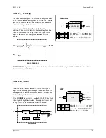
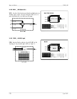
Page 82: ...A L I M I T 1 B L I M I T Process 1 Alarm A LIMIT S Real 110 0 Process 1 Alarm B LIMIT S Real 10 0 2 A L I M I T 2 B L I M I T Process 2 Alarm A LIMIT S Real 110 0 Process 2 Alarm B LIMIT S Real 10 0 3 A L I M I T 3 B L I M I T Process 3 Alarm A LIMIT S Real 110 0 Process 3 Alarm B LIMIT S Real 10 0 4 A L I M I T 4 B L I M I T Process 4 Alarm A LIMIT S Real 110 0 Process 4 Alarm B LIMIT S Real 10 ...

Page 83: ...e enabled or disabled when in the quickset ALARM mode The configuration allows an alarm to be enabled or disabled on a cold start When an alarm is disabled it will not operate but will retain settings for return to the enabled mode Operator faceplate functions relating to alarms are described in the sections describing the specific faceplate controls and displays All alarms have the following feat...

Page 84: ...e 3 LOOP is used to index reads and writes to Modbus parameters The LOOP must be entered to enable Modbus and Modbus TCP communications Range pointers for both the process setpoint and valve bargraphs must be configured to define the range of the variable inputs to P S and V If these parameters are not configured the bargraphs will be scaled using the engineering range of 0 00 to 100 00 The range ...

Page 85: ... longer whenever the bargraph flashes Bargraph flashing is controlled by the priority setting of alarms or events Output PF Pulse ofF will go high for 0 5 sec when the flashing bargraph is stopped e g pressing the ACK button P BLOCK DIAGRAM INput units Engineering scaling Valve DPP 4 2 3 4 5 T C 0 5 3 P 2 Process INput units Engineering scaling Process Process DPP S S P S P INput units Engineering...

Page 86: ...block tag output null INPUT C H loop tag block tag output null INPUT B H loop tag block tag output null INPUT F H loop tag block tag output null I N P U T I I I I N N N N P P P P U U U U T T T T B C D F E Rev 3 3 2 56 ODD Operator Display for Discrete Indication Control ODD function blocks are one of five operator displays that can be used on a one per loop basis to configure the local operator di...

Page 87: ...UM353 1B Function Blocks April 2012 3 57 Manual A M T O F F O n I0 O0 SV 103 Manual A M T O n O n IF OF SV 206 Block Diagram D i g D i s p 1 i ware PC Faceplate Display ...

Page 88: ... ODP function blocks are one of five operator displays that can be used on a one per loop basis to configure local operator display functions as well as network parameters See the i ware PC faceplate example on the next page The ODP function block can provide up to 8 groups of two pushbuttons and one selector switch Each group includes One normally open pushbutton identified as PB1 on the local fa...

Page 89: ...dback Messages STOP RUN 1 0 X X AUTO MAN A M Group 1 Message STOP START MS1036 81 82 PB2 PB1 81 82 8A 8M 83 PB3 8F Note Numbers shown on input lines indicate values of unconfigured inputs STOP RUN 1 0 X X AUTO MAN A M Group 8 Message Groups 2 to 7 1 1 1 0 0 1 1 1 0 0 Feedback Messages i ware PC Faceplate Display ...

Page 90: ... only with a network workstation and not allow operation from the local display This may be desired with a sequence logic loop where local operation is not needed but a workstation needs access to force I O or sequence parameters for recipe changes Messages will be available over Modbus and Modbus TCP Refer to Section 5 Network Communications for mapped data points 1 The of Recipe messages can be ...

Page 91: ...to console or from console computer to local each time the input is toggled Also when output LO goes high output CN will also go high and CM will go low indicating that the control source will change to Console whenever Local is disabled either by toggling input CL or from a network command The Computer CM state can be set high using a network command The NL output will normally be connected to th...

Page 92: ...rm start outputs and comparator functions will be initialized at the state prior to power down and all dynamic elements will be initialized at the current input on the first scan During a cold start all outputs and comparator states will be set to zero to be activated by the block functions All dynamic elements will be initialized at the current input on the first scan t D S t D DG S 1 P S BLOCK D...

Page 93: ...OVERRIDE status when a priority level higher than 0 the default has been selected If an override input is not configured the individual selector will output the other input When no inputs are configured the block will output 0 0 and the OS status will be set low 0 BLOCK DIAGRAM A O1 B C OR TRUTH TABLE A B C Output 1 0 0 0 0 0 0 0 0 0 0 0 0 0 1 1 1 1 1 1 1 1 1 1 1 1 1 OR 1 1 1 1 1 1 Primary Input O...

Page 94: ...elapsed time will ramp from 0 0 to the value of ON TIME and remain there until P goes low 0 Output RT remaining time equals ON TIME ET POWER UP During a warm start when PU LAST is set to YES the block will initialize at the input output states and elapsed time in effect at the instant power down occurred A cold start will initialize the input output states and elapsed time to 0 Pulse Input ONE SHO...

Page 95: ...on is used in toggle applications such as changing the function of the ODC or ODS function blocks In the sustained mode the switch will alternate positions each time the button is pressed An unconfigured NC input defaults to 0 and an unconfigured NO input to 1 The button can be remotely activated through a command over Modbus or Modbus TCP This block operates with an operator faceplate that includ...

Page 96: ...sed in toggle applications such as changing the function of the E I function block In the sustained mode the switch will alternate positions each time the button is pressed An unconfigured NC input defaults to 0 and an unconfigured NO input to 1 The button can be remotely activated through a command over Modbus or Modbus TCP This block operates with an operator faceplate that includes green and re...

Page 97: ...rn when released In the sustained mode the switch will alternate positions each time the button is pressed An unconfigured NC input defaults to 0 and an unconfigured NO input to 1 The button can be remotely activated through a command over Modbus or Modbus TCP where explicitly stated in Section 6 Data Mapping This block operates with an operator faceplate that includes green and red LEDs that are ...

Page 98: ...a 0 W0 will affect the communication state as defined by the associated logic in Figure 3 1 All unconfigured inputs will be treated as low 0 except OK RD RN and HE which will be treated as high 1 Three of the output states EO EMERG IK INTRLK and FD FAILED can be configured for priorities 0 5 This will affect the flashing etc as previously described for other controller status conditions These stat...

Page 99: ... 0 RUN AND AND OR ST EN RUN RUN AND HELD RUN R 0 W 1 W 0 F F S R HOLD HO HO AND RUN OR AND EN HO AND HO 13 FD HE R 1 0 HELD AND AND OR HO EN HELD HELD AND RUN HELD R 1 0 DONE DN R 0 W 1 W 0 F F S R PCOMP OR AND RUN AND DONE OR DONE READY AND ABORTED EO DONE R 1 0 ABORTED R 0 W 1 W 0 F F S R ABORT AND HELD AND DONE OR ABORTED ABORTED AND READY IK EN AND ABORTED READY OR AND EO unconfigured 0 unconf...

Page 100: ...M R S 1 1 O1 F P S BLOCK DIAGRAM Absolute Value AE 1 A Auto Initialize I Setpoint Process Absolute Error Output Feedback Lead Lag R INput units Engineering scaling INput units Engineering scaling scaling inverse scaling MR T PD Controller RanGe PoinTeR ENG UNITS Limit 3 3 O 103 3 r3 Process PD CONTROLLER D G DIRect ACTing H NO YES NO O1 Output CONTROLLER PD ESN 000 P S F A PD Setpoint Feedback Aut...

Page 101: ...e process should deviate from the setpoint during the on off cycles This parameter can be set manually or can be configured as AUTO When AUTO is configured the autotuner will set the DEV to 4 times the HYS This is the minimum value needed to provide good autotuning results The HYS parameter is the amount that the process must deviate from setpoint before switching the output in the opposite direct...

Page 102: ...arm or cold power up the output will be initialized to MINSCALE and all dynamic elements will be initialized at the current input on the first scan t D S t D DG S 1 e A PG t I S 1 1 O1 F P S BLOCK DIAGRAM Absolute Value AE 1 A Auto Initialize I Setpoint Process Absolute Error Output 1 Feedback Lead Lag R Limit INput units Engineering 3 3 O 103 3 scaling INput units Engineering scaling scaling inve...

Page 103: ...autotuning results The HYS parameter is the amount that the process must deviate from setpoint before switching the output in the opposite direction This value must be at least equal to or slightly greater than any process noise band If the noise band cannot be determined the autotuner will compute it at the start of an autotuning exercise when the HYS parameter has been configured as AUTO The STE...

Page 104: ...nt using a switch block t D S t D DG S 1 e A PG t I S 1 1 O1 F P S BLOCK DIAGRAM Absolute Value AE 1 A Auto Initialize I Setpoint Process Absolute Error Output 1 Feedback Lead Lag R Limit INput units Engineering 3 3 O 103 3 scaling INput units Engineering scaling scaling inverse scaling X AG Adaptive Gain PID Adaptive Gain Controller ENG UNITS r3 RanGe PoinTeR Process PIDAG CONTROLLER D G DIRect A...

Page 105: ... AUTO When AUTO is configured the autotuner will set the DEV to 4 times the HYS This is the minimum value needed to provide good autotuning results The HYS parameter is the amount that the process must deviate from setpoint before switching the output in the opposite direction This value must be at least equal to or slightly greater than any process noise band If the noise band cannot be determine...

Page 106: ...tep at which time AO will go to the AEP value for the completed step The current sequencer step can be changed by any of the following six events 1 the Reset input R going high 1 moving it to step 1 2 Goto Step input GS going high 1 forcing the sequencer to the step indicated by the whole value of input SN 3 the Step Forward input SF going high 1 moving it to the next higher step unless on the las...

Page 107: ... Output will go to the AEP value for the completed step POWER UP During a warm start if PU LAST is set to YES all outputs step number track variable and remaining step time will be initialized at the last values prior to power fail During a cold start all outputs are initialized to 0 and the PRSEQ is in a reset condition TV TC SF SB GS SN Track Variable Track Command Step Forward Step Backward Ste...

Page 108: ...it is important to keep the resolution to the minimum necessary for operation changes It will take the operator longer turning the pulser if the resolution is too high For example if only 0 1 changes are needed configure a 0 100 range as 0 0 100 0 and not 0 000 100 000 During Hot or Warm start the QHD will power up in the last position during a Cold start at the 10 range value BLOCK DIAGRAM O1 Pul...

Page 109: ...input TC or TV is not configured its value will be set to 0 The TO Tracked Output is normally used in applications where an external device is being used to set a ratio in place of the RATIO parameter R is then set to 1 0 When it is desired to have the output of the RATIO block track the TV variable the external device is forced to track TO Input E will then equal TV Ax 1 0 and therefore the RATIO...

Page 110: ...o the value of ON TIME The output will be high for a period equal to ON TIME x AT OFF TIME 0 0 The output will be low 0 for a period equal to OFF TIME and will be high for a period equal to ON TIME x AT The time cycle equals ON TIME x AT OFF TIME POWER UP With the PU LAST parameter set to YES during a hot or warm power up the block will initialize the input output states and elapsed time at the la...

Page 111: ...t E is low 0 the output will track the analog input If input E is not configured the limit action of the block will be enabled BLOCK DIAGRAM A O1 E Enable UPRATE DOWNRATE Analog Input Output 1 RL FL Rising Limit Falling Limit Switch shown in the enabled position with Input E not connected AU AD Adaptive Rate Up Adaptive Rate Down Rev 2 Analog Input RATE LIMITER E R D I N U A UP RATE units minute S...

Page 112: ... PU LAST is set to YES the block will initialize at the input output states and elapsed time at the instant power down occurred A cold start will initialize the input output states and elapsed time to 0 3 2 76 ROUT_ Relay Outputs ROUT_ function blocks provide SPDT contacts activated by function block input C The relay will turn on when the block input is high 1 and will turn off when low 0 Two rel...

Page 113: ...a high 1 output for one scan cycle each time input P transitions from a low 0 to a high 1 BLOCK DIAGRAM R O1 S RS FLIP FLOP TRUTH TABLE S R LO O1 1 0 0 0 X X X 1 0 1 0 0 0 0 1 1 S SET Input R RESET Input O1 Output LO Last Output Output 1 Reset Set X don t care BLOCK DIAGRAM Output 1 P O1 Pulse Input Reset RS FLIP FLOP O1 Output 1 RS FLIP FLOP RSF_ ESN 000 R Set S E Exec Seq No H 001 to 250 S T U P...

Page 114: ...blem with the clock or the clock has been reset The Battery Status will go high if the battery is low The battery low condition could also cause a clock reset when the power is cycled These outputs can be used to trip a User Status alarm condition or in logic to force a loop to manual standby hold etc Status outputs could be intermittent and may require configuration of function block logic to lat...

Page 115: ...ion on the three input signals Unused inputs will be set equivalent to the lowest real value when configured as a HI selector and to the highest real value when configured as a LO selector BLOCK DIAGRAM SELECTOR C O1 HI LO A B Input B SIGNAL Input C Input A Output Analog Input SCALER RanGe PoinTeR S loop tag block tag null O1 Output 1 SCALER SCL_ ESN 000 A E S N Exec Seq No H 001 to 250 A T U P N ...

Page 116: ...The setpoint block also has two inputs LU and LD that can be used to limit pulser changes in one direction This can be used if another function block is limiting the setpoint and it is desired not to allow the operator to adjust the setpoint block to a value beyond the external limit POWER UP The function block can be configured to power up in various conditions during a warm start If the PU LAST ...

Page 117: ...e next page for additional details regarding priorities The SPLIM function block has an RG PTR parameter input R that defines the normal operating range of the block Limit settings can be made within 10 to 110 of the range pointer values If the range pointer is not configured a range of 0 0 to 100 0 will be used If a range change is made the current limit value will be moved to be the same value w...

Page 118: ...sed R input will be set high 1 and an unused S input will be set low 0 POWER UP During a warm start when PU LAST is set to YES the block will initialize at the input output states at the instant power down occurred A cold start will initialize the input output states to 0 3 2 86 SRT_ Square Root SRT_ function blocks compute the square root of input signal A The input has a built in low limit that ...

Page 119: ...n scaling functions BLOCK DIAGRAM O1 A B Input A Input B Output 1 Rev 2 3 2 88 TAN_ TANGENT TAN__ function blocks accept a radian input and output the tangent of that angle Input X TANGENT O1 Output 1 O1 TAN X TAN ESN 000 X E Exec Seq No 000 to 250 000 X T U P N I INPUT X loop tag block tag output null S N BLOCK DIAGRAM O1 X Input X Output 1 TAN X Input A SUBTRACTION O1 Output 1 SUBTRACTION SUB_ E...

Page 120: ...The running total can be reset when input R goes high 1 Input R is executed prior to reading input S on each scan cycle Unconfigured inputs will be set to 0 When the EDGETRIG parameter is set to 1 the total will increment on each 0 to 1 transition on input S When the EDGETRIG parameter is set to 0 the total will increment on each 1 to 0 transition The total will be retained during a WARM HOT start...

Page 121: ...OR The XOR output will be low 0 when all configured inputs are low 0 or when all configured inputs are high 1 A O1 B C XOR XOR TRUTH TABLE A B C Output 1 0 0 0 0 0 0 0 0 0 0 0 0 1 1 1 1 1 1 1 1 1 1 1 1 1 0 0 1 1 1 1 1 X03136S0 Input A TRANSFER SWITCH O1 Output 1 TRANSFER SWITCH TSW_ ESN 000 A E S N Exec Seq No H 001 to 250 C T U P N I INPUT B H loop tag block tag output null Switch Command SC B T ...

Page 122: ...Function Blocks UM353 1B April 2012 3 92 ...

Page 123: ...alog Input block for this information b A number of function blocks have parameters that may be affected by range pointers The range pointer limits the setting of parameter values to within 10 to 110 of the range If a range is changed the current parameter values will be changed to the same within the new range For example if the range is 0 0 100 0 and the Alarm 1 Limit setting is 90 0 and the ran...

Page 124: ... Function Block RG PTR Range Pointer Loop01 PID OR INPUT A Input A Loop01 PID O1 ESN Exec Seq No 20 AOUT1 Analog Output 1 Function Block RG PTR Range Pointer Loop01 PID OR INPUT S Input S Loop01 A M O1 ODC Operator Display for Controllers P RG PTR P Range Pointer Loop01 AIN1 OR V RG PTR V Range Pointer Loop01 PID OR INPUT P Input P Process Loop01 AIN1 O1 INPUT S Input S Setpoint Loop01 SETPT O1 IN...

Page 125: ...ter Loop01 PID OR INPUT A Input A Loop01 PID O1 ESN Exec Seq No 20 AOUT1 Analog Output 1 Function Block RG PTR Range Pointer Loop01 PID OR INPUT S Input S Loop01 A M O1 ODC Operator Display for Controllers P RG PTR P Range Pointer Loop01 AIN1 OR V RG PTR V Range Pointer Loop01 PID OR INPUT P Input P Process Loop01 AIN1 O1 INPUT S Input S Setpoint Loop01 SETPT O1 INPUT V Input V Valve Loop01 A M O1...

Page 126: ...T1 S DOUT2 S S E I Ext Int Transfer Switch Function Block INPUT ST Input ST Loop01 PB2SW PS INPUT E Input E Loop01 AIN2 O1 INPUT I Input I Loop01 SETPT O1 ESN Exec Seq No 15 A M Auto Manual Function Block RG PTR Range Pointer Loop01 PID OR INPUT A Input A Loop01 PID O1 ESN Exec Seq No 30 OR01 OR Function Block INPUT A Input A Loop01 E I ES INPUT B Input B Loop01 A M MS ESN Exec Seq No 35 AOUT1 Ana...

Page 127: ...01 PID OR X RG PTR X Range Pointer Loop01 AIN2 OR INPUT P Input P Process Loop01 AIN1 O1 INPUT S Input S Setpoint Loop01 E I O1 INPUT V Input V Valve Loop01 A M O1 INPUT X Input X X Variable Loop01 AIN2 O1 LOOP Loop 01 DOUT1 Digital Output 1 Function Block INPUT S Input S Loop01 ALARM A1 DOUT2 Digital Output 2 Function Block INPUT S Input S Loop01 ALARM A2 ...

Page 128: ...X DOUT1 S DOUT2 S S IRev 2 PB2SW PB2 Switch Function Block INPUT MD Input MD Loop01 E I SE ESN Exec Seq No 5 ALARM Alarm Function Block RG PTR Range Pointer Loop01 AIN1 OR INPUT P Input P Loop01 AIN1 O1 INPUT D Input D Loop01 E I O1 ESN Exec Seq No 20 PID PID Controller Function Block RG PTR Range Pointer Loop01 AIN1 OR INPUT P Input P Loop01 AIN1 O1 INPUT S Input S Loop01 E I O1 INPUT F Input F L...

Page 129: ...01 PID OR X RG PTR X Range Pointer Loop01 AIN2 OR INPUT P Input P Process Loop01 AIN1 O1 INPUT S Input S Setpoint Loop01 E I O1 INPUT V Input V Valve Loop01 A M O1 INPUT X Input X X Variable Loop01 AIN2 O1 LOOP Loop 01 DOUT1 Digital Output 1 Function Block INPUT S Input S Loop01 ALARM A1 DOUT2 Digital Output 2 Function Block INPUT S Input S Loop01 ALARM A2 ...

Page 130: ...S SPLIM HS O1 LS PID O1 AE AW SR P D A TV TC EM S D P S F A I A LU LD Valve Captive Flow S P V OR02 O1 A B C LOOP01 OR01 O1 A B C RATIO O1 TO A E TV TC DIV01 O1 N SCL01 O1 A D Y 0 00 100 00 PRCT 0 00 100 00 PRCT 0 00 100 00 PRCT X 0 50 1 50 CF WF Rev 2 RATIO Ratio Function Block HI LIMIT HI Range LIMIT 1 50 LO LIMIT LO Range LIMIT 0 50 INPUT A Input A Loop01 AIN1 O1 INPUT TC Input TC Loop01 OR01 O...

Page 131: ...2 OR V RG PTR V Range Pointer Loop01 PID OR X RG PTR X Range Pointer Loop01 AIN1 OR Y RG PTR Y Range Pointer Loop01 SCL01 OR INPUT P Input P Process Loop01 AIN2 O1 INPUT S Input S Setpoint Loop01 SPLIM O1 INPUT V Input V Valve Loop01 A M O1 INPUT X Input X X Variable Loop01 AIN1 O1 INPUT Y Input Y Y Variable Loop01 DIV01 O1 LOOP Loop 01 DIV01 Division Function Block INPUT N Input N Loop01 AIN2 O1 ...

Page 132: ... PID OR INPUT A Input A Loop01 PID O1 ESN Exec Seq No 25 AOUT1 Analog Output 1 Function Block RG PTR Range Pointer Loop01 PID OR INPUT S Input S Loop01 A M O1 ODC Operator Display for Controllers P RG PTR P Range Pointer Loop01 AIN1 OR V RG PTR V Range Pointer Loop01 PID OR INPUT P Input P Process Loop01 AIN1 O1 INPUT S Input S Setpoint Loop01 SPLIM O1 INPUT V Input V Valve Loop01 A M O1 LOOP Loop...

Page 133: ...PID O1 AE AW SR P D A TV TC EM S D P S F A I LU LD Valve Process S P V LOOP01 SETPT TV TC O1 AIN2 QS O1 AOUT2 QS ALARM A1 A2 A3 A4 A M O1 AS NA MS ES SS PID O1 AE AW SR P D A TV TC EM S D P S F A I LU LD Valve Process S P V LOOP02 Rev 2 Loop 01 SETPT Setpoint Function Block RG PTR Range Pointer LOOP01 AIN1 OR INPUT TV Input TV LOOP01 AIN1 O1 INPUT TC Input TC LOOP01 A M NA ESN Exec Seq No 5 ALARM ...

Page 134: ...ck RG PTR Range Pointer LOOP02 AIN2 OR INPUT P Input P LOOP02 AIN2 O1 INPUT D Input D LOOP02 SETPT O1 ESN Exec Seq No 10 PID PID Controller Function Block RG PTR Range Pointer LOOP02 AIN2 OR INPUT P Input P LOOP02 AIN2 O1 INPUT S Input S LOOP02 SETPT O1 INPUT F Input F LOOP02 A M O1 INPUT A Input A LOOP02 A M AS ESN Exec Seq No 15 A M Auto Manual Function Block RG PTR Range Pointer LOOP02 PID OR I...

Page 135: ...changed all configured references will automatically be changed to the new tag PB2SW PS E I O1 SE SI IS ES NC NO MD ST E I IO SETPT TV TC O1 AIN1 QS O1 ALARM A1 A2 A3 A4 A M O1 AS NA MS ES SS PID O1 AE AW SR P D A TV TC EM P S F A I LU LD Primary Process S P V SETPT TV TC O1 AIN2 QS O1 AOUT1 QS ALARM A1 A2 A3 A4 A M O1 AS NA MS ES SS SPLIM HS O1 LS PID O1 AE AW SR P D A TV TC EM S D P S F A I A LU...

Page 136: ...itch Function Block INPUT MD Input MD SEC E I SE ESN Exec Seq No 15 SPLIM Setpoint Limit Function Block RG PTR Range Pointer SEC AIN2 OR INPUT A Input A PRIM A M O1 ESN Exec Seq No 20 E I Ext Int Transfer Switch Function Block INPUT ST Input ST SEC PB2SW PS INPUT E Input E SEC SPLIM O1 INPUT I Input I SEC SETPT O1 ESN Exec Seq No 25 PID PID Controller Function Block RG PTR Range Pointer SEC AIN2 O...

Page 137: ...gured references will automatically be changed to the new tag PB2SW PS E I O1 SE SI IS ES NC NO MD ST E I IO SETPT TV TC O1 AIN1 QS O1 ALARM A1 A2 A3 A4 A M O1 AS NA MS ES SS SPLIM HS O1 LS PID O1 AE AW SR P D A TV TC EM P S F A I A LU LD Primary Process S P V SETPT TV TC O1 AIN2 QS O1 AOUT1 QS ALARM A1 A2 A3 A4 A M O1 AS NA MS ES SS SPLIM HS O1 LS PID O1 AE AW SR P D A TV TC EM S D P S F A I A LU...

Page 138: ... INPUT S Input S Setpoint SEC SPLIM O1 INPUT V Input V Valve SEC A M O1 LOOP Loop 02 Primary Loop cont ALARM Alarm Function Block RG PTR Range Pointer PRIM AIN1 OR INPUT P Input P PRIM AIN1 O1 INPUT D Input D PRIM SPLIM O1 ESN Exec Seq No 20 PID PID Controller Function Block RG PTR Range Pointer PRIM AIN1 OR INPUT P Input P PRIM AIN1 O1 INPUT S Input S PRIM SPLIM O1 INPUT F Input F SEC AIN02 O1 IN...

Page 139: ...sters with the first containing the most significant and the second the least significant portion of the floating point number The 353 uses an IEEE reverse format See Table 3 4 in Section 3 2 7 AIE_ Analog Input Ethernet for more information on floating point formats The station supports Modbus function codes 01 02 03 04 05 06 08 and 16 Section 6 Data Mapping provides a listing of available data a...

Page 140: ...hat cannot access the extended area In addition there are a number of registers reserved for the mappings of Modbus registers used in the Peer to Peer functionality of the Ethernet function blocks Sequencer Mask Configurations x10001 x18000 Real Time Trip Block Configurations x19001 x19021 Sequencer Time Analog Configurations x20001 x20999 Timer Function Block Configurations x21001 x21009 Reserved...

Page 141: ...ion upload download or on line monitoring associated with the i config Graphical Configuration Utility are not described 6 1 CONNECTING TO i ware PC Modbus OPC Server The i ware PC Operator Interface software includes a Modbus OPC server that when communicating with a station can auto populate its database with the number and type of loops configured in the station All tag names used in the OPC da...

Page 142: ...r Data 16 bit Integer Code R W Description Range Register MB GDS R Global Data Size LIL 7 256 0007 0100 n a ST R Station Type 6 0006 40001 SSW R W Station Status Word see Station Status Word see coils SE R W Station Error 0 32767 00000 7FFF 40002 NCL R No of Control Loops of ODC 0 255 0000 00FF 40003 NSL R No of Seq Loops of ODS 0 255 0000 00FF 40004 RAM R RAM Size size in K bytes 0 65535 0000 FFF...

Page 143: ...Gateway Address 4 3 0 255 4 0 255 40073 IPM1 R IP Mask 3 1 0 255 2 0 255 40074 IPM2 R IP Mask 3 3 0 255 4 0 255 40075 EBS R Ethernet Board Speed 0 auto 1 10M 2 100M 40076 EBD R Ethernet Board Duplex 0 auto 1 half duplex 2 full duplex 40077 PPR R Ethernet Board Peer to Peer Rate 0 25 0 5 1 2 5 10 sec 40078 Spares 40079 40100 Software Revisions Development Release MSB 128 to 255 80 FF Major Rev MSB ...

Page 144: ...ange Coil MB ASE R 1 Active Station Event 1 0 00001 SEN R W 1 Station Event Not Ackl d 1 0 00002 FSB R 1 Flashing Station Bargraph 1 0 00003 SDV R 1 Station Database Valid 1 0 00004 CCL R Config Change Counter LSB bit 1 0 n a CCH R Config Change Counter MSB bit 1 0 n a SCH R 1 Station Configuration Hold 1 0 00007 SRB R W 1 Station Run Bit 1 0 00008 OOS R W 1 Station Alarms Out of Service 1 0 00009...

Page 145: ...teger Data Controller ODC Code R W Description Range Register MB L PI R Process 3 3 to 103 3 0 0FFF 40201 10 1 L SI R W Setpoint 3 3 to 103 3 0 0FFF 40202 10 1 L VI R W Valve 3 3 to 103 3 0 0FFF 40203 10 1 L XI R X Variable 3 3 to 103 3 0 0FFF 40204 10 1 L YI R Y Variable 3 3 to 103 3 0 0FFF 40205 10 1 L RI R W Ratio 0 00 to 38 40 80 0F80 40206 10 1 L BI R W Bias 100 0 100 80 0F80 40207 10 1 L Tlm...

Page 146: ...6 0000 0006 40466 30 1 L A4TI R W Alarm 4 Type 0 6 0000 0006 40467 30 1 L A1PI R W Alarm 1 Priority 1 5 0001 0005 40468 30 1 L A2PI R W Alarm 2 Priority 1 5 0001 0005 40469 30 1 L A3PI R W Alarm 3 Priority 1 5 0001 0005 40470 30 1 L A4PI R W Alarm 4 Priority 1 5 0001 0005 40471 30 1 L CAI R W Controller Action 1 DIR 0 REV 40472 30 1 spare 0 0000 40473 30 1 spare 0 0000 40480 30 1 Sequencer ODS MAS...

Page 147: ...B Type 0 3 0000 0003 40460 30 1 L P2ATI R W Process 2 Alarm A Type 0 3 0000 0003 40461 30 1 L P2BTI R W Process 2 Alarm B Type 0 3 0000 0003 40462 30 1 L P3ATI R W Process 3 Alarm A Type 0 3 0000 0003 40463 30 1 L P3BTI R W Process 3 Alarm B Type 0 3 0000 0003 40464 30 1 L P4ATI R W Process 4 Alarm A Type 0 3 0000 0003 40465 30 1 L P4BTI R W Process 4 Alarm B Type 0 3 0000 0003 40466 30 1 L P1API ...

Page 148: ... DPP 0 to 5 0000 0005 41212 30 1 spare 0 0000 41213 30 1 spare 0 0000 41230 30 1 Sequencer ODS MASK Configurations Code R W Description Range Register MB L S006G0I R W Step 6 Group 0 Input Mask 0000 FFFF 41201 30 1 L S006G0O R W Step 6 Group 0 Output Mask 0000 FFFF 41202 30 1 L S006G1I R W Step 6 Group 1 Input Mask 0000 FFFF 41203 30 1 L S006G1O R W Step 6 Group 1 Output Mask 0000 FFFF 41204 30 1 ...

Page 149: ...nalog Output Real 41953 20 1 L SAEPF R Step Analog End Point Real 41955 20 1 L SRTF R W Step Remaining Time Real 41957 20 1 L SSTF R Sequencer Step Time Real 41959 20 1 L SNSF R Sequencer Number of Steps Real 41961 20 1 L SNGF R Sequencer Number of Groups Real 41963 20 1 L SNRF R Sequencer Number of Recipes Real 41965 20 1 L CRNF Current Recipe Number Real 41967 20 1 R W spare 0 00000000 41969 20 ...

Page 150: ...Register MB L DYT01ET R DYT01 Elapsed Time Real 42451 60 1 L DYT01RT R W DYT01 Remaining Time Real 42453 60 1 L OST01ET R OST01 Elapsed Time Real 42455 60 1 L OST01RT R W OST01 Remaining Time Real 42457 60 1 L RCT01ET R RCT01 Elapsed Time Real 42459 60 1 L RCT01RT R W RCT01 Remaining Time Real 42461 60 1 L ROT01ET R ROT01 Elapsed Time Real 42463 60 1 L ROT01RT R W ROT01 Remaining Time Real 42465 6...

Page 151: ... Manual Reset 0 00 100 00 43957 60 1 L ADF R W Autotune Deviation auto 0 2 5 25 43959 60 1 L AHF R W Autotune Hysteresis auto 0 0 5 10 0 43961 60 1 L ASF R W Autotune Step initial 5 40 43963 60 1 L APGF R Autotune Proportional Gain 0 001 1000 0 43965 60 1 L ATIF R Autotune Integral Time 0 001 4000 0 min 43967 60 1 L ATDF R Autotune Derivative Time 0 00 100 00 min 3969 60 1 L HDF R W On Off Control...

Page 152: ...alog End Point Real 43981 60 1 L S009TIM R W Step 9 Time Period min Real 43983 60 1 L S009AEP R W Step 9 Analog End Point Real 43985 60 1 L S010TIM R W Step 10 Time Period min Real 43987 60 1 L S010AEP R W Step 10 Analog End Point Real 43989 60 1 spares 44991 44009 60 1 Controller ODA Code R W Description Range Register MB L Q1MNF R W Quickset 1 MIN SCALE Real 43951 60 1 L Q1MXF R W Quickset 1 MAX...

Page 153: ...ontal Bar Message 5 ASCII Char 45491 100 1 spares 0000 45492 45550 100 1 Sequencer ODS Code R W Description Range Register MB L TAG R Loop Tag 12 ASCII Char 45451 100 1 L PMSG R Primary Message 8 ASCII Char 45457 100 1 L SMSG R Secondary Message 12 ASCII Char 45461 100 1 L CMSGa R Conditional Message a 16 ASCII Char 45467 100 1 L CMSGb R Conditional Message b 16 ASCII Char 45475 100 1 L CMSGc R Co...

Page 154: ... 45466 100 1 L I4T R Input 4Tag 6 ASCII Char 45469 100 1 L I5T R Input 5 Tag 6 ASCII Char 45472 100 1 L I6T R Input 6 Tag 6 ASCII Char 45475 100 1 L I7T R Input 7 Tag 6 ASCII Char 45478 100 1 L I8T R Input 8 Tag 6 ASCII Char 45481 100 1 L I9T R Input 9 Tag 6 ASCII Char 45484 100 1 L IAT R Input A Tag 6 ASCII Char 45487 100 1 L IBT R Input B Tag 6 ASCII Char 45490 100 1 L ICT R Input C Tag 6 ASCII ...

Page 155: ...sed for Variable Loop Integer Data with displays other than ODP L G6Tag R Group 6 Tag 6 ASCII Char 41201 30 1 L G6P1T R Group 6 PB1 Tag 6 ASCII Char 41204 30 1 L G6P2T R Group 6 PB2 Tag 6 ASCII Char 41207 30 1 L G6SAT R Group 6 Switch Position A Tag 6 ASCII Char 41210 30 1 L G6SMT R Group 6 Switch Position M Tag 6 ASCII Char 41213 30 1 L G6F1T R Group 6 Feedback 1 Tag 6 ASCII Char 41216 30 1 L G6F...

Page 156: ... Alarm 4 is Active 1 0 00321 48 1 L N4 R W 1 Alarm 4 is Not Acknowledged 1 0 00322 48 1 L E4 R W 1 Alarm 4 is Enabled 1 0 00323 48 1 L OS2 R W 1 Alarms Out of Service 1 0 00324 48 1 L CC R 1 Configuration has Changed 1 0 00325 48 1 L NA R W 1 Unacknowledged Loop Event 1 0 00326 48 1 L AE R 1 Active Loop Event 1 0 00327 48 1 L NSS R W 1 Not Ack d STANDBY 1 0 00328 48 1 L NOR R W 1 Not Ack d Overrid...

Page 157: ... W 1 Alarm 1 is Enabled 1 0 00314 48 1 L A2 R 1 Alarm 2 is Active 1 0 00315 48 1 L N2 R W 1 Alarm 2 is Not Acknowledged 1 0 00316 48 1 L E2 R W 1 Alarm 2 is Enabled 1 0 00317 48 1 L A3 R 1 Alarm 3 is Active 1 0 00318 48 1 L N3 R W 1 Alarm 3 is Not Acknowledged 1 0 00319 48 1 L E3 R W 1 Alarm 3 is Enabled 1 0 00320 48 1 L A4 R 1 Alarm 4 is Active 1 0 00321 48 1 L N4 R W 1 Alarm 4 is Not Acknowledge...

Page 158: ... 1 Process 3 Alarm A is Active 1 0 00312 48 1 L P3AN R W 1 Process 3 Alarm A is Not Acknowledged 1 0 00313 48 1 L P3AE R W 1 Process 3 Alarm A is Enabled 1 0 00314 48 1 L P3BA R 1 Process 3 Alarm B is Active 1 0 00315 48 1 L P3BN R W 1 Process 3 Alarm B is Not Acknowledged 1 0 00316 48 1 L P3BE R W 1 Process 3 Alarm B is Enabled 1 0 00317 48 1 L P4AA R 1 Process 4 Alarm A is Active 1 0 00318 48 1 ...

Page 159: ...tatus 1 Auto 0 Manual 1 0 00322 48 1 L DBS R W Discrete B Status 1 Auto 0 Manual 1 0 00323 48 1 L DCS R W Discrete C Status 1 Auto 0 Manual 1 0 00324 48 1 L DDS R W Discrete D Status 1 Auto 0 Manual 1 0 00325 48 1 L DES R W Discrete E Status 1 Auto 0 Manual 1 0 00326 48 1 L DFS R W Discrete F Status 1 Auto 0 Manual 1 0 00327 48 1 L D0O R W Discrete 0 Output 1 ON 0 OFF 1 0 00328 48 1 L D1O R W Disc...

Page 160: ...ss PB2 1 00313 48 1 L G5S3 R W Group 5 Auto Man Switch 1 0 00314 48 1 L G5FS R Group 5 Feedback Status 1 0 00315 48 1 L G6P1 W Group 6 Press PB1 1 00316 48 1 L G6P2 W Group 6 Press PB2 1 00317 48 1 L G6S3 R W Group 6 Auto Man Switch 1 0 00318 48 1 L G6FS R Group 6 Feedback Status 1 0 00319 48 1 L G7P1 W Group 7 Press PB1 1 00320 48 1 L G7P2 W Group 7 Press PB2 1 00321 48 1 L G7S3 R W Group 7 Auto ...

Page 161: ...09112 32 1 L ABORTED R 1 ABORTED 1 0 09113 32 1 spare R 1 0 09114 32 1 spare R 1 0 09115 32 1 spare R 1 0 09116 32 1 Code R W Description Range Coil MB L EMERG EO R 1 Emerg Override 1 0 09117 32 1 L NotAck dEO R W 1 EO Not Ack d 1 0 09118 32 1 L INTRLK IK R 1 INTRLK 1 0 09119 32 1 L NotAck d IK R W 1 IK Not Ack d 1 0 09120 32 1 L FAILED FD R 1 FAILED 1 0 09121 32 1 L NotAck dFD R W 1 FD Not Ack d ...

Page 162: ...Seq Group 0 cur step State of Input F 1 0 01527 SG0SO0 R Seq Group 0 cur step State of Output 0 1 0 01528 SG0SOF R Seq Group 0 cur step State of Output F 1 0 01543 SGFKI0 R Seq Group F cur step masK for Input 0 1 0 02216 SGFKIF R Seq Group F cur step masK for Input F 1 0 02231 SGFSI0 R Seq Group F cur step State of Input 0 1 0 02232 SGFSIF R Seq Group F cur step State of Input F 1 0 02247 SGFSO0 R...

Page 163: ...TD01 Data 169 0 100 128 3968 48185 A1D170 R ATD01 Data 170 0 100 128 3968 48186 Writing to the sample time will reset all data points A1D1 through A1D170 to 0 A2RMN R ATD02 MIN SCALE Real 48201 A2RMX R ATD02 MAX SCALE Real 48203 A2DPP R ATD02 Decimal Point Position 0 5 48205 A2EU R ATD02 Engineering Units 6 ASCII Char 48206 A2YR R ATD02 Year V2 0 5 1997 48209 A2MT R ATD02 Month V2 0 5 1 12 48210 A...

Page 164: ... 128 3968 48585 A3D170 R ATD03 Data 170 0 100 128 3968 48586 Writing to the sample time will reset all data points A3D1 through A3D170 to 0 A4RMN R ATD04 MIN SCALE Real 48601 A4RMX R ATD04 MAX SCALE Real 48603 A4DPP R ATD04 Decimal Point Position 0 5 48605 A4EU R ATD04 Engineering Units 6 ASCII Char 48606 A4YR R ATD04 Year V2 0 5 1997 48609 A4MT R ATD04 Month V2 0 5 1 12 48610 A4DY R ATD04 Day V2 ...

Page 165: ...128 3968 48819 A5D168 R ATD05 Data 168 0 100 128 3968 48984 A5D169 R ATD05 Data 169 0 100 128 3968 48985 A5D170 R ATD05 Data 170 0 100 128 3968 48986 Writing to the sample time will reset all data points A5D1 through A5D170 to 0 Notes 1 A read of any Time Stamp Data i e Year Month Day Hour Minute Second or Sample Time will update all Loop data registers Additional data reads of Trend data within t...

Page 166: ...p 3 Input Mask 0000 FFFF 410007 S001G3O R W Step 1 Group 3 Output Mask 0000 FFFF 410008 S250GEI R W Step 250 Group E Input Mask 0000 FFFF 417997 S250GEO R W Step 250 Group E Output Mask 0000 FFFF 417998 S250GFI R W Step 250 Group F Input Mask 0000 FFFF 417999 S250GFO R W Step 250 Group F Output Mask 0000 FFFF 418000 Real TimeTrip Block Configurations Code R W Description Range Register MB RTT01Y R...

Page 167: ...0987 S248TIM R W Step 248 Time Period min Real 420989 S2488AEP R W Step24 8 Analog End Point Real 420991 S249TIM R W Step 249 Time Period min Real 420993 S249AEP R W Step 249 Analog End Point Real 420995 S250TIM R W Step 250 Time Period min Real 420997 S250AEP R W Step 250 Analog End Point Real 420999 Timer Function Block Configurations Code R W Description Range Register MB DYT01T R W Delay Timer...

Page 168: ...Data Mapping UM353 1B April 2012 6 28 ...

Page 169: ...d in a user supplied enclosure located out of doors or in a location whose environmental parameters exceed controller operating specifications A thin bead of silicon sealant is often applied between the controller s Display Assembly and the mounting panel to prevent air or liquid leakage at this joint Do not mount the controller where direct sunlight can strike the faceplate or case Direct sunligh...

Page 170: ...st contain a fan to force air to flow around equipment and throughout the cabinet preventing hot spots from developing Forced air conditioning may be required in high density panels or consoles Periodically change or clean air filters CONTAMINANTS The controller case is slotted to permit circulation of clean cooling air Liquids and corrosive gases must not be allowed to enter the case Whether the ...

Page 171: ...each connector has a removable portion that can be separated from the case mounted portion wired and then reattached This section will describe cover removal connector separation and connector installation COVER AND CONNECTOR REMOVAL AND INSTALLATION Removal 1 Squeeze the cover slightly about 2 5 mm down from the top and push the cover upward See Figure 7 1 As shipped from the factory the cover is...

Page 172: ...sh cover upward 2 Pull cover out from rear panel To install or remove cover squeeze both sides 1 16 to clear alignment tabs Ethernet cable cutout Figure 7 1 Cover Installation and Removal 7 3 2 Panel and Rack Mounting Guidelines The panel face should provide a flat and rigid mounting surface Reinforce the back of the panel if there is a possibility that the panel face will bow Raceways conduit and...

Page 173: ...o 8 32 x 1 fillister head screws Thread the mounting screws into the mounting clips See Figure 7 4 2 From in front of the panel insert the controller case into the panel cutout 3 Slightly rotate the top mounting clip to fit it into the case cutout Then straighten the clip and partially tighten the mounting screw Insert straighten and partially tighten the bottom clip 4 Square the controller with t...

Page 174: ...efore connecting or disconnecting power signal or other circuit Observe all pertinent regulations regarding installation in hazardous area 7 4 1 Wiring Guidelines Electrical Connections Power I O and Modbus network connections to a basic controller are completed through removable connectors with terminals H N and 3 26 When the controller includes an I O Expander board connectors with terminals 27 ...

Page 175: ... the station common and case safety ground Connector Terminal and Ground Screw Torque Specifications connector terminals 5 in lbs 0 56 N m green case safety ground screw 20 in lbs 2 26 N m Crimp On solderless Connectors A pin style crimp on connector can be used when two or more wires or a combination of wires and component leads are to be inserted into a connector terminal at the rear of the case...

Page 176: ... Digital Input 4 DIN4 44 Digital Input 4 DIN4 45 Analog Input Universal 1 a AINU1a 46 Analog Input Universal 1 b AINU1b 47 Analog Input Universal 1 c AINU1c 39 Transmitter Power 26 Vdc XMTR 40 Transmitter Station Common COM 41 Analog Input 4 AIN4 42 Analog Input Common AINC Terminal Function ID and Number Analog Input 1 2 Common AINC 21 Analog Input 2 AIN2 22 Analog Input 3 AIN3 23 Analog Input 3 ...

Page 177: ... 2 DIN2 14 40 COM Transmitter Station Common Digital Input 3 DIN3 15 41 AIN4 Analog Input 4 Digital Input 3 DIN3 16 42 AINC Analog Input Common Analog Output 1 AOUT1 17 43 DIN4 Digital Input 4 Analog Output 1 2 Common AOUTC 18 44 DIN4 Digital Input 4 Analog Output 2 AOUT2 19 45 AINU1a Analog Input Universal 1 a Analog Input 1 AIN1 20 46 AINU1b Analog Input Universal 1 b Analog Input 1 2 Common AIN...

Page 178: ...stor and a signal input wire are to be inserted in the same connector terminal A connector should also be used when two wires of significantly different gauges would otherwise be inserted in a single connector terminal Perform the following steps for each analog input 1 Select an analog input terminal pair for connection of the input signal wiring Refer to Table 7 1 and the following illustrations...

Page 179: ...olated Ground Isolated Power Note See Table 7 1 for AINU2 terminals MG00508a Universal Converter Isolated Inputs Model 353 Rear Terminals 3 75 45 46 47 48 Controller Circuitry Millivolt Source _ Ground Isolated Ground Isolated Power Note See Table 7 1 for AINU2 terminals MG00509a Universal Converter Isolated Inputs Model 353 Rear Terminals A 4 20 mA Input B Millivolt Input Figure 7 8 Universal Ana...

Page 180: ...rs and wiring so that excessive stress is not placed on a component wire or connection 7 4 3 Analog Output Wiring 4 20 mA 1 5 Vdc Analog output functions blocks are AOUT1 AOUT2 and AOUT3 Figure 7 9 shows connections for an external device that accepts 4 20 mA For an external device that needs 1 5 Vdc see Figure 7 10 Refer to Section 7 4 1 for wiring guidelines 6 17 Common Ground Bus Earth Ground 1...

Page 181: ...IN2 MG00510b Transmitter Supply Model 353 Rear Terminals Common Ground Bus 26 Vdc Earth Ground Common 40 Controller Circuitry _ 36 37 38 _ 24V External Supply DINU1 DINU2 MG000713b 35 39 Current Limiter Limits current to 6 mA maximum Current Limiter Transmitter Supply Model 353 Rear Terminals Or any station common terminal See Table 7 1 for DIN3 terminals A DIN1 and 2 B DINU1 and 2 Figure 7 11 Dig...

Page 182: ...ut Isolated 5 8 Inductive Load with Suppression Diode See Note Common Ground Bus 26 Vdc Earth Ground Controller Terminals Common 9 Controller Circuitry _ Digital Output 24 Vdc Resistive Load Resistive Load C Current Output Isolated Notes 1 Inductive load must be shunted with a transient suppression diode 1N4005 or equiv to prevent damage to station output circuit 2 See Table 7 1 for DOUT2 terminal...

Page 183: ...ungrounded junction connect cable shield to AINUc_ Analog Input Universal Common Isolated Power Isolated Ground Universal Converter Isolated Inputs _ MG00512a Thermocouple Wire Model 353 Rear Terminals Figure 7 13 Universal Analog Input AINU1 Thermocouple Input Thermocouple reference junction RJ installation 1 Slip a length of insulating sleeving over the portion of each reference junction lead th...

Page 184: ...lly tighten the terminal screws to 5 in lbs 4 Repeat the above steps if the other AINU function block is to be used as a thermocouple input 7 4 6 RTD Input Wiring Wiring for 2 3 and 4 wire RTDs is shown in Figure 7 15 Make connections as outlined in Section 7 4 1 Note the wire jumper between terminals 47 and 48 when a 2 wire RTD is installed 45 46 47 48 45 46 47 48 Jumper 2 Wire RTD 3 Wire RTD 45 ...

Page 185: ...Shown 7 4 8 Relay Output Wiring Function blocks ROUT1 and ROUT2 are located on the I O Expander board They provide two single pole double throw relay outputs as shown in Figure 7 17 Relay contact ratings are stated in Section 13 6 MPU Controller Board Specifications The load connected to a closed contact should draw a current between the minimum and maximum contact ratings A resistive load is reco...

Page 186: ...k Shown below are the jumper locations and identifiers for the Entrelec Isolated Converter shown in Figure 7 18 Rt INT1 R INT2 E INT3 For access to jumpers carefully remove the side of the module that has the jumper label Entrelec ILPH 084 233 11 Isolated Converter RS485 link on one pair AG00336a 120Ω 7 4 10 Ethernet Wiring A sample architecture and a brief description are presented in the Introdu...

Page 187: ... Model 353 G NCA NCB 3 4 G 3 4 6 6 RS232 Cable Note 1 To Personal Computer Serial Port Note 6 RS485 Cable Note 2 Common Ground Bus Single Point Earth Ground Case Safety Ground Case Safety Ground Model 353 Model 353 RS485 to RS232 Isolated Converter Entrelec ILPH 084 233 11 L CTRL M RxD G COM A TxD B RxD D TxD E RxD C P P 0V 5V V V 8 5 26 Vdc K TxD 2 RxD 3 TxD 4 DTR 8 CTS 5 SG J F Rt R E Jumper Set...

Page 188: ...inal 6 Figure 7 19 Model 353 to Siemens SIREC D Recorder Analog Input Wiring 7 4 12 Power Wiring Basic connections for AC and DC power input are shown in Figure 7 20 Wiring guidelines are given in Section 7 4 1 H Model 353D Rear Terminals X03106S0 N External Power 120 240 Vac 25W 47 63 Hz Hot Neutral Earth Ground External Power 24 Vdc 25W Earth Ground Model 353A Rear Terminals H N DC To DC Power S...

Page 189: ...c MG00504a First Model 353 In The Row Last Model 353 In The Row Circuit Breaker or Fuse White Black Case Rear Terminals G H Terminal on rear of case Green ground screw at top center of rear terminal area H Hot or N Neutral or G Ground Green Earth Ground Ground Bus Figure 7 22 Daisy Chained Power Wiring 1 Strip ground wire s 3 8 10 mm to 1 2 13 mm Clamp the ground wire s under the green square pres...

Page 190: ...n blocks 1 to 5 Vdc Analog output function blocks 4 to 20 mA Thermocouple Type J Upscale Break RTD CAL ZERO 0 C CAL FULL 500 C CAL VIEW 3 3 to 103 3 Slidewire CAL ZERO 0 CAL FULL 100 CAL VIEW Contact factory Ohms CAL ZERO 0 Ohms CAL FULL 5000 Ohms CAL VIEW Contact factory Millivolt CAL ZERO 19 0 mV CAL FULL 19 0 mV CAL VIEW 0 TO 100 Section 11 0 provides calibration procedures that may be used to ...

Page 191: ...ton controls the operation of the PB2SW PB 2 transfer SWitch function block when the block has been configured for use within the Active Loop See the function block details for more information on PB2SW A M Pushbutton controls the operation of an A M Auto Manual function block when the block has been configured for use within the Active Loop See the function block details for more information on A...

Page 192: ...e alphanumeric display When the button is pressed the units that apply to the displayed variable will appear in the alphanumeric e g TC2053 P deg F TC2053 V PRCT After 3 seconds the alphanumeric display will return to the variable tag S Bargraph this vertical bargraph displays the scaled range of the controller setpoint in the Active Loop Bargraph height shows the setpoint as the of range value Th...

Page 193: ...n to return to the on line displays When in the configuration mode this button will step up to the next configuration level TAG has a dual purpose When in the normal operation mode pressing the button will scroll the complete tag name of the Active Loop in the alphanumeric display The tag will scroll one character at a time starting on the right e g T TI TIC When in the configuration mode this but...

Page 194: ...hanumeric display will alternate between AUTOTUNE and the loop tag name and will stop alternating when the autotune program has been completed Once completed the controller will return to the mode prior to autotune initiation When the POST AT in the controller block is set to auto transfer the recommended tuning parameters will automatically be transferred to the controller and it will return to a...

Page 195: ... for the HYS and DEV can be considered as described in the section Autotuner Warnings Steady State Conditions must be established for the process and controller prior to starting an autotune exercise The autotuner can be initiated while in manual or auto Steady state is reached when the present valve signal has brought the process to its present value and the setpoint is equal to the process When ...

Page 196: ...utotuner Warnings do not terminate the autotune exercise and are normally eliminated by increasing the HYS and or the DEV settings In some cases they may have been caused by load changes that occurred during the autotune exercise The autotuner will still derive recommended tuning values but they will not automatically be transferred to the controller if that feature was requested The warnings can ...

Page 197: ...figuration topics 9 1 1 Connections and Power 1 Connect power to the controller Refer to Controller nameplate for model number and then to Section 13 Model Designation and Specifications for power requirements Refer to Section 7 Installation for connections WARNING Electrical shock hazard Explosion hazard Can cause death or injury Remove power from all wires and terminals before working on equipme...

Page 198: ...ETPT and INPUT V is configured as the output of function block A M 9 1 4 Auto Manual In FCO101 the A M block is configured to switch Valve control from the PID controller in AUTO to the Pulser Knob in Manual Press the A M button to toggle the display between the Loop01 S setpoint parameter and the Loop01 V valve parameter Turn the pulser knob while displaying the valve parameter in manual to chang...

Page 199: ...ulser knob to display 1 in the last digit Display should read 0 00001 9 Now press the left arrow TAG button Notice that the decimal place will move one place every time the button is pressed Press the arrow button until the display reads 100 000 and then press the STORE button 10 Press STEP UP 11 Turn the pulser knob or use the arrow button to display MAXSCALE 12 Press STEP DOWN to display 100 000...

Page 200: ...e flashing Alarms may also be configured as self clearing Try changing the alarm priority to 4 using the Configuration Road Map in Figure 2 1 or the following steps 1 Press ENTER EXIT CONF LOOP should be displayed 2 Press STEP DOWN twice until VIEW appears on the display 3 Press the right arrow button 3 times or turn the pulser knob until EDIT FB appears on the display 4 Press STEP DOWN A M will b...

Page 201: ... this feature enabled In FCO101 the SETPT function block has the QUICK SET feature enabled as a default Press the QUICK button and note that you can scroll through the following Setpoint features RAMP ON OFF Ramp RATE TARGET setpoint and POWER UP SETPOINT The ramp feature can either use a ramp TIME or a ramp RATE USE RATE is set to YES as the default see SETPT function block details in Section 3 2...

Page 202: ... follow the Configuration Road Map in Figure 2 1 or do the following steps 1 Press ENTER EXIT CONF 2 Press STEP DOWN twice to display VIEW 3 Use the right arrow button or the pulser knob to display EDIT FB 4 Press STEP DOWN for Function Block menu 5 Use the right arrow button or the pulser knob to display AIN1 6 Press STEP DOWN for parameter menu 7 Use the right arrow button or the pulser knob to ...

Page 203: ...number on the P I drawing should match the model number on the controller s case Compare the model number to the Model Designation table in Section 13 to be sure the proper boards are installed NOTE When power is applied to the controller an installed hardware list can be viewed in the STATN function block Refer to Section 3 1 3 for board description and ID 2 Check all wiring between the controlle...

Page 204: ...Controller and System Test UM353 1B April 2012 9 8 ...

Page 205: ...e desired or should particular problems arise which are not covered sufficiently for the purchaser s purposes the matter should be referred to the local Siemens sales office The use of unauthorized parts in the repair of the equipment or tampering by unqualified personnel will result in dangerous conditions that can cause death serious injury or equipment damage Follow all safety instructions cont...

Page 206: ...oard handling guidelines 2 Loosen the Display Assembly s two faceplate screws One screw is above the numeric display the other behind the flip down door at the bottom of the faceplate See Figure 10 1 as needed 3 Pull the Assembly from the panel about 1 5 38 mm 4 Look behind the Assembly and locate the display cable then open the connector locking levers on the Assembly mounted connector to eject t...

Page 207: ...LECTRONIC ASSEMBLIES Semiconductor devices must be protected from electrostatic discharge A properly grounded conductive wrist strap must be worn whenever a circuit board assembly is handled or touched A service kit with a wrist strap and static dissipative work mat is available from mail order and local electronic supply companies LITHIUM BATTERY PRECAUTIONS Each MPU Controller board has a lithiu...

Page 208: ...ndicates that most initial service incidents are of this nature Additional troubleshooting avenues are also possible For example a series of test configurations may be created and implemented to exercise various function blocks within the controller Section 3 describes each function block This type of troubleshooting analysis is intended to be implemented in an off line test bench situation On lin...

Page 209: ...UM353 1B Maintenance April 2012 10 5 Figure 10 2 MPU Controller Board Figure 10 3 MultiMediaCard MMC Inserting and Ejecting MMC Activity LED Ethernet Activity LED Fuse Ethernet Connector Display Cable ...

Page 210: ...or Codes ERROR CODE DESCRIPTION CORRECTIVE ACTION 101 Board type test Replace Controller board 102 DRAM error Replace Controller board 103 SRAM error Replace Controller board 104 Flash CRC error Press ENTER to reset and retest controller If error remains replace Controller board or reinstall firmware 202 Constant Data CRC Test Controller operation suspended Press ENTER to load Controller board def...

Page 211: ...rsal Analog Input 1 A D Error AINU1 TC 0007 7 I O Expander Board Universal Analog Input 1 T C Burnout AINU1 RJ 0008 8 I O Expander Board Universal Analog Input 1 Reference Junction Error AINU2 AD 0009 9 I O Expander Board Universal Analog Input 2 A D Error AINU2 TC 000A 10 I O Expander Board Universal Analog Input 2 T C Burnout AINU2 RJ 000B 11 I O Expander Board Universal Analog Input 1 Reference...

Page 212: ...Emergency Override PCOM block INTRLK None Interlocked PCOM block DFAIL None Device Failed PCOM block MAX LOOP None Maximum Loop Size S HI Lim None Setpoint HI Limit S LO Lim None Setpoint LO Limit U1 Status None User Status 1 U2 Status None User Status 2 ATUNE W1 None Autotuner Warning hys desamp 0 2 see Section 8 3 for W details ATUNE W2 None Autotuner Warning Deviation Ratio is HI see Autotune p...

Page 213: ...tall the Expander board FileErr5 The file contains a database revision that is not supported The file is not usable The database revision must be Rev 4 00 or higher 10 5 ASSEMBLY REPLACEMENT The following describes replacement of the controller s assemblies The subsections below are organized in the sequence of controller disassembly and reassembly Most subsections have Removal and Installation pa...

Page 214: ...crew on the Controller s case an unpainted area on the panel or a grounded static dissipative work mat 3 Loosen the Display Assembly s two faceplate screws One is above the numeric display and one behind the flip down door at the bottom of the faceplate 4 Pull the Assembly from the panel about 1 5 38 mm 5 Look behind the Assembly and locate the display cable from the MPU Controller board Open the ...

Page 215: ...ly face up and lift each mounting screw upward until the threaded portion contacts the bezel Turn each screw counterclockwise to unscrew it from the bezel A screwdriver may be needed once a screw is started 2 Remove the flip down door by pressing on the door near its pivot point to free the door from the bezel Fixed Board Retainer Numeric Display 2 Alphanumeric Display 2 Connector Flexible Board R...

Page 216: ... toward the Controller board and withdrawing the connector from the socket 5 Grasp the loop in the front edge of the MPU Controller board and pull the board straight out of the case 6 Place the MPU Controller board in a static shielding bag INSTALLATION 1 While wearing a grounded wrist strap remove MPU Controller board from static shielding bag 2 Partially insert the MPU Controller board into the ...

Page 217: ...om the board mounted connector 2 Remove the Controller board and I O Expander board if present as described in preceding sections 3 Inside the case at the rear panel press the locking tab on the cable mounted connector upward and withdraw the connector from the rear panel mounted connector A long flat blade screwdriver may be needed to press the locking tab upward and release the connector INSTALL...

Page 218: ...AT12 by default FAT 32 and cards larger than 2 GB were not supported at the time this manual was produced Configuration File Names A configuration created and saved at a 353 faceplate will be stored on the MultiMediaCard with the controller s 8 character serial number and a 3 character extension as the file name This file name can be edited see the notes in Figure 2 2 A configuration designed in i...

Page 219: ...se a precision current source The 250 ohm precision range resistor installed across the input terminals for calibration should remain with the station connected across that set of terminals to eliminate the voltage drop variation due to resistor tolerance Allow the Station to warm up for an hour prior to calibration The ambient temperature should be close to normal operating conditions The control...

Page 220: ...L appears on upper display 10 Set the precision voltage source to the zero input value 0 000 to 1 000 Vdc 11 Press STORE to lock in the desired value If ENTER COM appears in the alphanumeric display security is enabled and steps 1 through 5 must be performed to store the calibration Otherwise go to step 14 1 The numeric display shows 000000 with the right most digit flashing Rotate the pulser knob...

Page 221: ...r Knob to select the desired parameter CAL ZERO shown on the alphanumeric display 9 Press the STEP DOWN button to enter the VALUE level CAL appears on display 10 Rotate the Pulser Knob to set the zero output to 4 00 mA on the digital multimeter or electronic calibrator 11 Press the STORE button to lock in the desired value If ENTER COM appears in the alphanumeric display go to Section 11 1 step 13...

Page 222: ...Calibration UM353 1B April 2012 11 4 ...

Page 223: ...oard s on board power supply furnishes DC operating voltages to all plug in assemblies and to external process transmitters connected to the rear terminals The I O Expander board provides additional I O Ethernet communications is standard MPU Controller Board MPU Power Supply Display Assembly with Operator Faceplate RS232 MMJ 11 Power Input 26 Vdc to Transmitters Digital Inputs 1 3 4 20 mA Analog ...

Page 224: ...face and a real time clock Two serial ports are available for bi directional asynchronous communications Terminals NCA and NCB provide an RS485 connection for Modbus network communications An MMJ 11 connector on the underside of the Display Assembly provides an RS232 connection for creating and editing configurations using the optional PC Based Graphical Configuration Utility Since both ports are ...

Page 225: ...l information A configuration created on a PC running i config can be saved with a long file name more than 8 characters When the file is saved at the PC Windows will also create a short file name of 8 characters This short 8 character file name generated from the long file name will be displayed by the 353 The on board Power Supply circuit provides the power sources necessary for system power int...

Page 226: ...Circuit Description UM353 1B April 2012 12 4 ...

Page 227: ...e nameplate and other labels carry important information about the controller such as Model Number Bill of Material number P N No Serial Number and Certifications IMPORTANT Confirm a controller s model number and hazardous area certifications before installing applying power or servicing When circuit boards are added to a controller in the field nameplate information will not reflect the current p...

Page 228: ...Card MMC C Modification Options Not Required Controller modified per order Bill of Material N X Design Level Design Level B B Electrical Approval Not Required FM CSA Div 2 Class 1 Groups A B C D suitable for non incendive CE compliant FM CSA Div 2 Class 1 Groups A B C D suitable for non incendive CE compliant and ABS approved N 4 X 4 Contact Siemens Industry Inc Process Instrumentation Division fo...

Page 229: ...ne Permanent Instrument Tag Stainless steel tag permanently attached to the controller case One line with up to 24 characters can be specified Display Assembly Remote Mounting Kit 16353 54 For remote panel mounting of a Display Assembly Includes Flange Assembly Mounting Clips and Screws Display Ribbon Cable 48 inches 1219 mm long Installation Instruction Does not include the Display Assembly Commu...

Page 230: ...ty 1 3 75 Ohm 1 3W WW resistor qty 2 Insulating sleeving qty 5 Crimp on connector qty 6 100 Ohm reference junction for TC inputs qty 2 Crimp on Connector qty 18 O Ring Display Assembly qty 1 Fuse 120 240 Vac MPU Controller board 0 4A or 0 5A 250V SloBlo qty 1 Fuse 24 Vdc MPU Controller board 2A 250V SloBlo qty 1 Case Mounting Clip and 8 32 x 1 Fillister Hd Screw qty 2 each Case Ground Screw Green ...

Page 231: ...e Single ended Accuracy 0 10 Resolution 0 024 Software Output Type Analog configurable default 0 0 100 0 Normal Mode Rejection 50dB 60Hz Input Impedance 1 megohm Maximum Continuous Input Without Crosstalk 7 30 Vdc Without Damage 30 Vdc Analog Outputs 2 Standard Calibration 4 20 mAdc Zero 4 mAdc trim Span 16 mAdc trim Current Limits 2 4 mA to 21 6 mA Accuracy 0 1 Resolution 0 003 Software Input Typ...

Page 232: ... Ambient Temperature Effect 0 10 C C Type T Thermocouple Range Limits 240 C to 370 C 400 F to 698 F Performance Range 100 to 370 C Accuracy 0 5 C Conformity 0 06 Software Output Type Analog configurable C F R K Ambient Temperature Effect 0 07 C C Type E Thermocouple Range Limits 185 C to 1000 C 300 F to 1830 F Performance Range 0 to 1000 C Accuracy 0 5 C Conformity 0 06 Software Output Type Analog...

Page 233: ...t 0 04 C C Type US NBS126 RTD à 0 003902 Range Limits 185 C to 613 C 300 F to 1135 F Accuracy 0 4 C Software Output Type Analog configurable C F R K Ambient Temperature Effect 0 04 C C Type JIS C 1604 RTD à 0 003916 Range Limits 185 C to 610 C 300 F to 1130 F Accuracy 0 4 C Software Output Type Analog configurable C F R K Ambient Temperature Effect 0 04 C C Slidewire Resistance Range 500 5000 Ω So...

Page 234: ...t 1 Standard Calibration 4 20 mAdc Zero 4 mAdc trim Span 16 mAdc trim Accuracy 0 10 Resolution 0 003 Software Input Type Analog configurable default 0 0 100 0 Current Range Limits 2 4 to 21 6 mA dc Signal Reference Neg output tied to station common Output Load 800 Ohms Overvoltage Protection 30 Vdc Digital Input 1 Logic 1 Range 15 30 Vdc Logic 0 Range 0 1 Vdc Overvoltage 30 Vdc Minimum Required ON...

Page 235: ...oors or other area without environmental controls Enclosure User supplied Model 353 Case Installed inside enclosure Model 353 Display Exposed through enclosure to external environment Installation Requirements Refer to Section 7 Installation Temperature Limits Enclosure Internal Operating 0 to 50 C 32 to 122 F Enclosure External Operating 40 to 50 C 40 to 122 F Controller Storage 40 to 85 C 40 to ...

Page 236: ...g All pertinent regulations regarding installation in a hazardous area must be observed Precautions English For Class I Division 1 and Class I Division 2 hazardous locations y Use only factory authorized replacement parts Substitution of components can impair the suitability of this equipment for hazardous locations For Division 2 hazardous locations When the equipment described in this Instructio...

Page 237: ...hstand an impact of 0 085 Newton meter 0 753 pound force inch from a hollow steel impact sphere 50 8 mm 2 inches in diameter and an approximate mass of 113 4 grams 4 ounces Pressure Tests A force of 90 Newtons 20 pounds shall be applied from a metal rod 12 7 mm 0 50 inch in diameter the end of which is rounded The force shall be applied for one minute to any point on the overall enclosure except t...

Page 238: ...Model Designation and Specifications UM353 1B April 2012 13 12 EC Declaration of Conformity ...

Page 239: ...UM353 1B Model Designation and Specifications April 2012 13 13 Annex A to the EC Declaration of Conformity ...

Page 240: ...Model Designation and Specifications UM353 1B April 2012 13 14 ...

Page 241: ...B COS Cosine FB CRC Cyclical Redundancy Check D deviation denominator DAM Deviation Amplifier FB DC direct current DEG degrees DEV deviation DG derivative gain DIE Digital Input Ethernet FB DID Digital Input Discrete FB DIG digital DIN Digital Input FB DINU Digital Input Universal FB DIR direct DIS Digital Input_State DISP display DIV Division FB DLY delay DMM digital multimeter DNC Divide by N Co...

Page 242: ... PID Controller FB proportional integral derivative PIDAG PIDAG Controller FB proportional integral derivative adaptive gain PRSEQ Program Sequencer FB PTR pointer PU Power Up PUL pulse Q quality QHD Quickset Hold FB QS quick set quality status QSPI Queued Serial Peripheral Interface R reset Rankine RCT Repeat Cycle Timer FB RD received data Rev revision RG range RLM Rate Limiter FB RN recipe numb...

Page 243: ...UM353 1B Abbreviations And Acronyms April 2012 14 3 V valve volt s VAL value W watts WD watchdog XMTR transmitter XOR Exclusive OR Logic FB ZDO zero drop out ...

Page 244: ...Abbreviations And Acronyms UM353 1B 14 4 April 2012 ...

Page 245: ...puts At power up a design level B 353 controller with an I O Expander Board will now correctly clear an error status retained from the previous session Faceplate buttons UNITS and TAG now require only a single press to update the faceplate display Previously more that one press could be needed OPERATIONAL CONSIDERATIONS In the STATN Station Parameters function block parameters CONFG LO and PARAM L...

Page 246: ...ite http www usa siemens com pi Technical Publications in PDF Click the above link to go to the Siemens Internet site and then click Process Instrumentation In the column to the right click Support Manuals In the column to the left select the product line e g Pressure or Temperature or Controllers to open navigation and search panes All product designations may be trademarks or product names of Si...

Reviews: