


Configuration
2.4 Procedure when engineering
1FT7 Synchronous Motors
Configuration Manual, (PFT7S) 01/2009, 6SN1197-0AD13-0BP2
49
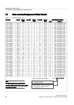
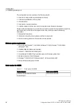
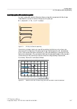
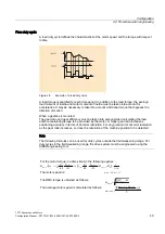
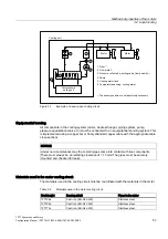
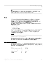
Free duty cycle
A load duty cycle defines the characteristics of the motor speed and the torque with respect
to time.
Figure 2-6
Example of a load duty cycle
A load torque is specified for each time period. In addition to the load torque, the average
load moment of inertia and motor moment of inertia must be taken into account for
acceleration. It may be necessary to take into account a frictional torque that opposes the
direction of motion.
When a gearbox is mounted:
The gear ratio and gear efficiency must be taken into account when calculating the load
and/or accelerating torque to be provided by the motor. A higher gear ratio increases
positioning accuracy in terms of encoder resolution. For any given motor encoder resolution,
as the gear ratio increases, so does the resolution of the machine position to be detected.
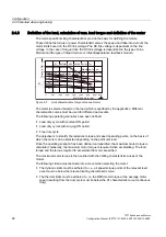
Note
The following formulas can be used for duty cycles outside the field weakening range. For
duty cycles in the field weakening range, the drive system must be engineered using the
SIZER engineering tool.
For the motor torque in a time slice Δ
t
i
the following applies:
(
)
•
1
•
)
+
+
•
60
2
•
(
+
•
•
60
2
•
+
=
i
M
M
t
n
J
i
t
n
J
J
M
*
5
L
/DV
t
L
L
/D
s
W
/DV W
L
L
/DV W
*
0
L
0RW
The motor speed is:
L
/D V W
L
0RW
i
n
n
•
=
The RMS torque is obtained as follows:
t
M
M
∑
Δ
•
=
2
0RWHII
L
0 RWL
T
The average motor speed is calculated as follows:
T
L
0RWN(
0RWN$
0RWPLWWHO
t
n
n
n
•
2
+
=
Summary of Contents for 1FT7 Series
Page 2: ......
Page 12: ...Preface 1FT7 Synchronous Motors 12 Configuration Manual PFT7S 01 2009 6SN1197 0AD13 0BP2 ...
Page 251: ......


