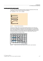


Configuration
2.4 Procedure when engineering
1FT7 Synchronous Motors
46
Configuration Manual, (PFT7S) 01/2009, 6SN1197-0AD13-0BP2
2.4.3
Definition of the load, calculation of max. load torque and definition of the motor
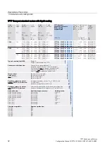
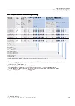
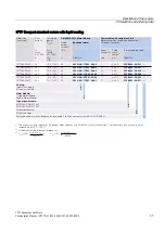
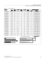
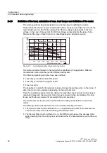
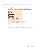
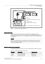
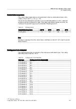
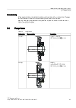
The motor-specific limiting characteristics provide the basis for defining the motors.
These define the torque or power characteristic versus the speed and take into account the
motor limits based on the DC link voltage. The DC link voltage is dependent on the line
voltage. In the case of torque drive the DC link voltage is dependent on the type of Line
Module and the type of infeed module or infeed/regenerative feedback module.
9ROWDJHOLPLWLQJ
FKDUDFWHULVWLF
0
PD[
GHWHUPLQHGE\FRQYHUWHUPRWRU
0RWRUVSHHGLQUSP
7RUTXHLQ1P
6
0D[LPXPWRUTXH
ZLWKILHOGZHDNHQLQJ
6
6
6
.
6
.
0
.
Figure 2-2
Limit characteristics for synchronous motors
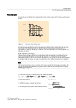
The motor is selected based on the load which is specified by the application. Different
characteristic curves must be used for different load events.
The following operating scenarios have been defined:
●
Load duty cycle with constant ON period
●
Load duty cycles with varying ON period
●
Free duty cycle
The objective is to identify characteristic torque and speed operating points, on the basis of
which the motor can be selected depending on the particular load.
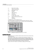
Once the operating scenario has been defined and specified, the maximum motor torque is
calculated. Generally, the maximum motor torque is required when accelerating. The load
torque and the torque required to accelerate the motor are added.
The maximum motor torque is then verified with the limiting characteristic curves of the
motors.
The following criteria must be taken into account when selecting the motor:
●
The dynamic limits must be adhered to, i.e., all speed-torque points of the relevant load
event must lie below the relevant limiting characteristic curve.
●
The thermal limits must be adhered to, i.e. the RMS motor torque at the average motor
speed resulting from the duty cycle must lie below the S1 characteristic curve (continuous
duty).
Summary of Contents for 1FT7 Series
Page 2: ......
Page 12: ...Preface 1FT7 Synchronous Motors 12 Configuration Manual PFT7S 01 2009 6SN1197 0AD13 0BP2 ...
Page 251: ......