17
Stabilizer Operation and User guide
version 5288-2 - 2018
Installation Instructions MASTER MAINTENANCE
2
Both pressure filter and return filter have pressure drop indicators. Check indicators every 6th month. The check have to be done
with oil temperature above 40˚C, and the most flow demanding consumer active. Filter element replacement are required if indica-
tors are in the red area.
Hydraulic oil replacement:
Every 4000 operating hours or every 3rd year. For heavy duty applications and commercial use, we recommend oil sample analyses
every year.
***Check oil color every 6th month. White or grey oil indicates water ingress or heavy condensation. This will require filter replace-
ment, oil replacement and flushing of the system. See schedule and Hydraulic system manual.
CONTROL SYSTEM
With the exception of keeping the electrical parts and wiring clean, dry and damage-free, no maintenance is required for these parts.
In general, all electrical equipment should be periodically checked to ensure that there are no mechanical damage or water build-up.
POWER UNIT
The power unit and its associated components require maintenance and have a lifetime so will in the future require replacement which
can be done preventively as indicated within the charts here, to avoid potential follow damage to other parts.
The hydraulic oil integrity must be checked as per the schedule by extracting a sample from the system for analyzis to ensure it is with-
ing the standards of its spesifications.
The hydraulic power unit motor should not stay unused for longer periods, and either manually rotated every 3 months or started to
ensure proper lubrication of the shafts and bearings on its shaft and bearings.
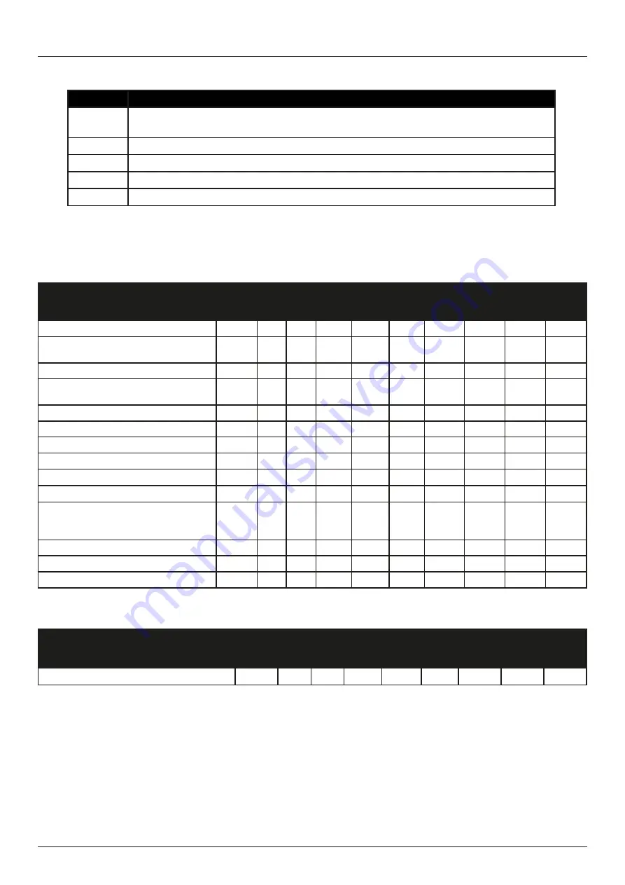
PREVENTATIVE MAINTENANCE SCHEDULE
The maintenance schedules in this section indicate the recommended preventative maintenance intervals for equipment supplied by
Side-Power. Components utilized in Side-Power Stabilizer Systems but not supplied by Side-Power are not included in the maintenance
schedule or under any Side-Power warranty.
The maintenance intervals are listed in hours of operation and time where relevant. Maintenance is to be performed according to this
schedule utilizing time or hour intervals, whichever comes first. . The maintenance schedule incorporates the minimum required main-
tenance to ensure correct operation of the system. Should these guidelines not be followed, the warranty for those items will be void.
To perform maintenance, replacement parts may need to be purchased. Refer to the recommended spares list and/or drawings for
associated part numbers.
Contact a Authorized Side-Power technician.
* If analysis of the scheduled oil sample indicates an elevated level of brass particles in the hydraulic system, the pumps should be
replaced or overhauled as soon as possible. Delay in component removal and system flushing will lead to contamination problems
throughout the hydraulic system. Erratic component operation may be a symptom of hydraulic fluid contamination.
*** 2000 operating hours or annually, whichever occurs first.
**** Fins should be inspected annually by diver if possible
The data in the table below is provided to assist the vessel in scheduling the appropriate service staff and coordination of vessel docking
(haul out) for maintenance procedures.
STABILIZER SYSTEM MAINTENANCE
Service and Maintenance
3
Installation Instructions MASTER MAINTENANCE
STABILIZER SYSTEM MAINTENANCE
Maintenance schedule
Service
level
250h 500h 2000h 4000h 8000h 12000h
When
out of
water
When
required
Months/
Year
1. Change oil in bearing assembly
1 D
36/3
rd
2. Inspect spherical bearings, and Main
Cylinders for external leakage
1 W
3. Inspect Stabilizer Manifolds
1 W
4. Inspect Stabilizer Manifolds Electrical
Connections
1 W
5. Inspect Fin Angle Sensor Belts
1 W
6. Inspect Twin Yoke Area
1 W
7. Inspect Hydraulic Hoses
1 W
8. Check Shaft Clearances
3 D
9. Replace Lower Shaft Seals
3 D
10. Replace Main Shaft Bearings
3 D
11. Inspect and replace Spherical Bear-
ings and Cylinder Pins if necessary.
(NOT relevant for SPS55)
2 W
12. Rebuild/Replace Cylinders
3 W
13.Replace the Fin Angle Belt
1 W
14. Replace hydraulic actuator hoses
3 W
36/3
rd
Maintenance schedule
Service
level
250h 500h 2000h 4000h 8000h 12000h
When
out of
water
When
required
1. Inspect Fin Surfaces
1 D ****
****
B. FINS
A. HULL UNIT
Level
Description
1
Onboard maintenance possible at sea
No shore support required
2
Shore supported maintenance and corrective measures
3
Trained personnel required - Side-Power personnel or equivalent
D
Dry - Vessel must be out of water to perform task
W
Wet - Vessel can be in water to perform task


