9
SE80/185T & SE100/185T Ignition Protected thruster assembly
1.0 - 2007
•
Explanation of electrical table
- All cable lengths are the total of + and - (to and from).
- Battery size is stated as minimum cold crank capacity, not Ah.
- Use slow fuse rated to hold stated Amp-Draw for min. 5 minutes.
* Cable size and main battery size when an extra bow battery with minimum the CCA mentioned as A is installed.
•
It is important that you use a good cable size and batteries with a high cranking capacity to feed the thruster, because it is the actual
voltage at the motor while running the thruster that decides the output rpm of the motor and thereby the actual thrust. Please see the
list below for advised min. sizes of cables and batteries. You can of course use larger cables for even better results.
•
A main switch (*C) that can take the load without noticable voltage drop must be installed in the main positive lead so the power
for the thruster can be turned off independently of the rest of the system when not on board or in emergencies. This should be placed
in an easily accessible place and the boats instructions should include information that this should be turned off like the other main
switches of the boat.
•
We also advice to install a fuse (*D) in the positive lead for protection agains short circuiting of the main cables. This fuse should be
of a adequate quality which normally means that it is physically large as these have less voltage drop than the simple / small ones. It
should be of the slow type and sized to take the amperage draw for atleast 5 minutes.
•
Remember to use ignition protected fuses and switches if fitted in areas that require this feature.
•
A circuit breaker can be used instead of the fuse and main power switch as long as the functionality is the same.
•
The cable ends must be fitted with terminals and these must be well isolated against contact with anything but the proper connection
point.
•
If the main switch and fuse are installed in the same gas area they also have to be ignition protected.
•
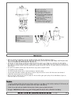
The negative / minus cable connects to the (-) terminal. Bolt M10. Tighten with 25 Nm / 18,43 lb/ft.
•
The positive / plus cable connects to the "+" terminal. Bolt M10. Tighten with 25 Nm / 18,43 lb/ft.
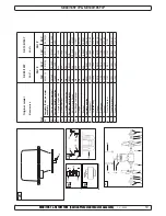
Electrical installation
Model
Voltage Nominal
current
draw
Min. battery
CCA
>7m total + & - 7-14m total + & - 15-21m total + & - 22-28m total + & - 28-35m total + & - 36-45m total + & -
Min.
Rec. Min.
Rec.
Min.
Rec.
Min.
Rec.
Min.
Rec.
Min.
Rec.
SE80/185T
12 V
530 A
DIN: 550
SAE:1045
mm
2
AWG
60
2/0
70
2/0
95
3/0
2x 70
2x 2/0
2x 70
2x 2/0
2x 95
2x 2/0
2x 95
2x 3/0
270*
2x 120
2x 4/0
340*
NA
NA
24 V
260 A
DIN: 300
SAE: 570
mm
2
AWG
25
1
35
1
35
1
50
1/0
60
2/0
70
2/0
70
2/0
95
3/0
95
3/0
120
4/0
120
4/0
2x 95
2x 3/0
SE100/185T
12 V
740 A
DIN: 750
SAE: 1425
mm
2
AWG
95
3/0
95
3/0
2x 70
2x 2/0
2x 95
2x 3/0
2x 95
2x 3/0
280*
250*
375*
NA
NA
NA
NA
24 V
340 A
DIN: 400
SAE: 760
mm
2
AWG
35
1
50
1/0
50
1/0
70
2/0
60
2/0
95
3/0
95
3/0
120
4/0
120
4/0
2x 95
2x 3/0
2x95
2x 3/0
2x 120
2x 4/0
Minimum and recommended cable dimensions can be identical due to safety margins and cable heat considerations for short cable lenghts.
* Minimum or recommended cable cross section in mm
2
Battery & cable recommendations:
9
SP75Ti / SP95Ti ignition protected thruster assembly
1.2.1 - 2007
•
Explanation of electrical table
- All cable lengths are the total of + and - (to and from).
- Battery size is stated as minimum cold crank capacity, not Ah.
- Use slow fuse rated to hold stated Amp-Draw for min. 5 minutes.
* Cable size and main battery size when an extra bow battery with minimum the CCA mentioned as A is installed.
•
It is important that you use a good cable size and batteries with a high cranking capacity to feed the thruster, because it is the actual
voltage at the motor while running the thruster that decides the output rpm of the motor and thereby the actual thrust. Please see the list
below for advised min. sizes of cables and batteries. You can of course use larger cables for even better results.
•
A main switch (*C) that can take the load without noticable voltage drop must be installed in the main positive lead so the power for the
thruster can be turned off independently of the rest of the system when not on board or in emergencies. This should be placed in an easily
accessible place and the boats instructions should include information that this should be turned off like the other main switches of the boat.
•
We also advice to install a fuse (*D) in the positive lead for protection agains short circuiting of the main cables. This fuse should be of a
adequate quality which normally means that it is physically large as these have less voltage drop than the simple / small ones. It should
be of the slow type and sized to take the amperage draw for atleast 5 minutes.
•
Remember to use ignition protected fuses and switches if fitted in areas that require this feature.
•
A circuit breaker can be used instead of the fuse and main power switch as long as the functionality is the same.
•
The cable ends must be fitted with terminals and these must be well isolated against contact with anything but the proper connection point.
•
If the main switch and fuse are installed in the same gas area they also have to be ignition protected.
•
The negative / minus cable connects to the (-) terminal. Bolt M10. Tighten with 25 Nm / 18,43 lb/ft.
•
The positive / plus cable connects to the "+" terminal. Bolt M10. Tighten with 25 Nm / 18,43 lb/ft.
Electrical installation
Battery
12V or 24V
+
-
*D
*C
Counter Nut
Nut
Washer
Cable terminal
Washer
Counter Nut
Nut
Washer
50 mm2
95 mm2
120 mm2
150 mm2
N / A
N / A
O
OOO+
OOOO+
2xOOO
N / A
50 mm2
70 mm2
95 mm2
120 mm2
150 mm2
O
OO+
OOO+
OOOO+
2xOOO
35 mm2
35 mm2
50 mm2
70 mm2
95 mm2
120 mm2
2
2
O
OO+
OOO+
OOOO+
70 mm2
105 mm2
150 mm2
175 mm2
N / A
N / A
OO+
OOOO
2xOOO
2xOOOO
N / A
70 mm2
95 mm2
120 mm2
150 mm2
180 mm2
OO+
OOO+
OOOO+
2xOOO
2xOOOO
50 mm2
50 mm2
70 mm2
95 mm2
120 mm2
150 mm2
O
O
OO+
OOO+
OOOO+
2xOOO
Table for s election of m ain cable,
battery, fuse and m ain-s witch
s izes .
up to 7m total
+
&
-
7 - 14m total
+
&
-
14 - 21m total
+
&
-
21 - 28m total
+
&
-
28 - 35m total
+
&
-
36 - 45m total
+
&
-
M odel
V oltage
Current
draw
M in. Cable
dim ension
M in.Battery
CCA by DIN
M in. Cable
dim ension
M in. Cable
dim ension
M in. Cable
dim ension
M in.Battery
CCA by Din
M in.Battery
CCA by DIN
M in. Cable
dim ension
M in. Cable
dim ension
M in.Battery
CCA by DIN
M in.Battery
CCA by Din
550 CCA Din
1045 CCA SA E
600 CCA Din
1140 CCA SA E
SP
75
T
i IP
12 V
480 A
550 CCA Din
1045 CCA SA E
24 V
240 A
300 CCA Din
570 CCA SA E
12V
Extr.batt
*
300 A
300 CCA Din
570 CCA SA E
300 CCA Din
570 CCA SA E
350 CCA Din
665 CCA SA E
350 CCA Din
665 CCA SA E
350 CCA Din
665 CCA SA E
550 CCA Din
1045 CCA SA E
300 CCA Din
570 CCA SA E
300 CCA Din
570 CCA SA E
350 CCA Din
665 CCA SA E
350 CCA Din
665 CCA SA E
750 CCA Din
1425 CCA SA E
750 CCA Din
1425 CCA SA E
750 CCA Din
1425 CCA SA E
SP
95
T
i IP
12 V
680 A
750 CCA Din
1425 CCA SA E
12V
Extr.batt
*
400 A
350 CCA Din
665 CCA SA E
24 V
340 A
400 CCA Din
760 CCA SA E
400 CCA Din
760 CCA SA E
M in.Battery
CCA by Din
400 CCA Din
760 CCA SA E
400 CCA Din
760 CCA SA E
450 CCA Din
855 CCA SA E
450 CCA Din
855 CCA SA E
350 CCA Din
665 CCA SA E
350 CCA Din
665 CCA SA E
350 CCA Din
665 CCA SA E
350 CCA Din
665 CCA SA E
350 CCA Din
665 CCA SA E
SE 60/185S ignition protected thruster assembly
1.0 - 2007
•
Explanation of electrical table
- All cable lengths are the total of + and - (to and from).
- Battery size is stated as minimum cold crank capacity, not Ah.
- Use slow fuse rated to hold stated Amp-Draw for min. 5 minutes.
* Cable size and main battery size when an extra bow battery with minimum the CCA mentioned as A is installed.
•
It is important that you use a good cable size and batteries with a high cranking capacity to feed the thruster, because it is the actual
voltage at the motor while running the thruster that decides the output rpm of the motor and thereby the actual thrust. Please see the
list below for advised min. sizes of cables and batteries. You can of course use larger cables for even better results.
•
A main switch (*C) that can take the load without noticable voltage drop must be installed in the main positive lead so the power
for the thruster can be turned off independently of the rest of the system when not on board or in emergencies. This should be placed
in an easily accessible place and the boats instructions should include information that this should be turned off like the other main
switches of the boat.
•
We also advice to install a fuse (*D) in the positive lead for protection agains short circuiting of the main cables. This fuse should be
of a adequate quality which normally means that it is physically large as these have less voltage drop than the simple / small ones. It
should be of the slow type and sized to take the amperage draw for atleast 5 minutes.
•
Remember to use ignition protected fuses and switches if
fitted
in areas that require this feature.
•
A circuit breaker can be used instead of the fuse and main power switch as long as the functionality is the same.
•
The cable ends must be
fitted
with terminals and these must be well isolated against contact with anything but the proper connection
point.
•
If the main switch and fuse are installed in the same gas area they also have to be ignition protected.
•
The negative / minus cable connects to the (-) terminal. Bolt M10. Tighten with 25 Nm / 18,43 lb/ft.
•
The positive / plus cable connects to the "+" terminal. Bolt M10. Tighten with 25 Nm / 18,43 lb/ft.
Electrical installation
Model
Voltage Nominal
current
draw
Min. battery
CCA
>7m total + & - 7-14m total + & - 15-21m total + & - 22-28m total + & - 28-35m total + & - 36-45m total + & -
Min.
Rec. Min.
Rec.
Min.
Rec.
Min.
Rec.
Min.
Rec.
Min.
Rec.
SE60/185S
12 V
340 A
DIN: 350
SAE:665
mm
2
AWG
35
1
50
1/0
60
2/0
95
3/0
95
3/0
2x 70
2x 2/0
120
4/0
2x95
2x 3/0
2x 95
2x 3/0
2x120
2x 4/0
2x120
2x 4/0
280*
24 V
170 A
DIN: 175
SAE: 332
mm
2
AWG
25
1
35
1
25
1
35
1
25
1
35
1
35
1
50
1/0
50
1/0
60
2/0
60
2/0
70
2/0
Battery & cable recommendations:
Minimum and recommended cable dimensions can be identical due to safety margins and cable heat considerations for short cable lenghts.
* Minimum or recommended cable cross section in mm
2
SP55S2i ignition protected thruster assembly
1.1 - 2006
•
Explanation of electrical table
- All cable lengths are the total of + and - (to and from).
- Battery size is stated as minimum cold crank capacity, not Ah.
- Use slow fuse rated to hold stated Amp-Draw for min. 5 minutes.
* Cable size and main battery size when an extra bow battery with minimum the CCA mentioned as A is installed.
•
It is important that you use a good cable size and batteries with a high cranking capacity to feed the thruster, because it is the actual
voltage at the motor while running the thruster that decides the output rpm of the motor and thereby the actual thrust. Please see the list
below for advised min. sizes of cables and batteries. You can of course use larger cables for even better results.
•
A main switch (*C) that can take the load without noticable voltage drop must be installed in the main positive lead so the power for the
thruster can be turned off independently of the rest of the system when not on board or in emergencies. This should be placed in an easily
accessible place and the boats instructions should include information that this should be turned off like the other main switches of the boat.
•
We also advice to install a fuse (*D) in the positive lead for protection agains short circuiting of the main cables. This fuse should be of a
adequate quality which normally means that it is physically large as these have less voltage drop than the simple / small ones. It should
be of the slow type and sized to take the amperage draw for atleast 5 minutes.
•
Remember to use ignition protected fuses and switches if fitted in areas that require this feature.
•
A circuit breaker can be used instead of the fuse and main power switch as long as the functionality is the same.
•
The cable ends must be fitted with terminals and these must be well isolated against contact with anything but the proper connection point.
•
If the main switch and fuse are installed in the same gas area they also have to be ignition protected.
•
The negative / minus cable connects to the (-) terminal. Bolt M10. Tighten with 25 Nm / 18,43 lb/ft.
•
The positive / plus cable connects to the "+" terminal. Bolt M10. Tighten with 25 Nm / 18,43 lb/ft.
Electrical installation
Battery
12V or 24V
+
-
*D
*C
Counter Nut
Nut
Washer
Cable terminal
Washer
Counter Nut
Nut
Washer
35 mm2
60 mm2
5 mm2
5 mm2
120 mm2
120 mm2
AWG 1
AWG OO
AWG OOO
AWG OOOO
AWG OOOO
2 x AWG OOOO
25 mm2
25 mm2
35 mm2
35 mm2
50 mm2
50 mm2
AWG 4
AWG 4
AWG 2
AWG 2
AWG 1
AWG 1
Min.Battery
CCA by Din
200 CCA Din
380 CCA SAE
200 CCA Din
380 CCA SAE
200 CCA Din
380 CCA SAE
250 CCA Din
475 CCA SAE
200 CCA Din
380 CCA SAE
400 CCA Din
760 CCA SAE
350 CCA Din
665 CCA SAE
Min.Battery
CCA by Din
12 V
330 A Din
627 A SAE
350 CCA Din
665 CCA SAE
24 V
160 A Din
304 A SAE
200 CCA Din
380 CCA SAE
SP
55
S2
i
IP
Min. Cable
dimension
Min.Battery
CCA by Din
350 CCA Din
665 CCA SAE
400 CCA Din
760 CCA SAE
400 CCA Din
760 CCA SAE
Min.Battery
CCA by DIN
Min. Cable
dimension
Min. Cable
dimension
Min.Battery
CCA by DIN
16 - 19m total
+
&
-
20 - 23m total
+
&
-
24 - 27m total
+
&
-
Model
Voltage
Current
draw
Min. Cable
dimension
Min.Battery
CCA by DIN
Min. Cable
dimension
Min. Cable
dimension
Table for selection of main cable,
battery, fuse and main-switch
sizes.
up to 7m total
+
&
-
8 - 11m total
+
&
-
12 - 15m total
+
&
-
SP55S2i ignition
protected thruster
assembly
1.1 - 2006
•
Exp
lan
atio
n o
f e
lec
tric
al t
abl
e
- A
ll c
abl
e le
ngt
hs
are
th
e to
tal
of
+
and
- (
to
and
fro
m).
- B
atte
ry
siz
e is
st
ate
d a
s m
ini
mum
co
ld
cra
nk
cap
aci
ty,
no
t A
h.
- U
se s
low
fus
e ra
ted
to h
old
sta
ted
Am
p-D
raw
for
min
. 5
min
ute
s.
* C
abl
e s
ize
an
d m
ain
ba
tte
ry
siz
e w
hen
an
ex
tra
bo
w b
atte
ry
with
m
ini
mum
th
e C
CA
men
tio
ned
as
A
is
ins
tal
led
.
•
It i
s im
por
tan
t th
at y
ou
use
a
goo
d c
abl
e s
ize
an
d b
atte
rie
s w
ith
a
hig
h c
ran
kin
g c
apa
city
to
fe
ed
the
th
rus
ter
, b
eca
use
it
is
the
ac
tua
l
vol
tag
e a
t th
e m
oto
r w
hile
ru
nni
ng
the
th
rus
ter
th
at d
eci
des
th
e o
utp
ut r
pm
of
th
e m
oto
r a
nd
the
reb
y th
e a
ctu
al t
hru
st.
Ple
ase
se
e th
e li
st
bel
ow
fo
r a
dvi
sed
m
in.
si
zes
of
ca
ble
s a
nd
bat
ter
ies
. Y
ou
can
of
co
urs
e u
se
lar
ger
ca
ble
s fo
r e
ven
be
tte
r re
sul
ts.
•
A m
ain
sw
itc
h (*
C) t
hat
ca
n ta
ke
the
lo
ad
with
out
no
tic
abl
e v
olta
ge
dro
p m
ust
be
in
sta
lle
d in
th
e m
ain
po
siti
ve
lea
d s
o th
e p
owe
r fo
r th
e
thr
ust
er c
an
be
tur
ned
of
f in
dep
end
ent
ly
of t
he
res
t o
f th
e s
yst
em
w
hen
no
t o
n b
oar
d o
r in
em
erg
enc
ies
. T
his
sho
uld
be
pl
ace
d in
an
ea
sily
acc
ess
ibl
e p
lac
e a
nd t
he b
oat
s in
stru
ctio
ns s
hou
ld i
nclu
de i
nfo
rm
atio
n th
at t
his s
hou
ld b
e tu
rne
d o
ff l
ike
the
oth
er m
ain
sw
itc
hes
of t
he b
oat
.
•
We
als
o a
dvi
ce
to
ins
tal
l a
fu
se
(*D
) in
th
e p
osi
tiv
e le
ad
for
pr
ote
ctio
n a
gai
ns
sho
rt c
irc
uiti
ng
of t
he
mai
n c
abl
es.
Th
is
fus
e s
hou
ld
be
of a
ade
qua
te
qua
lity
w
hic
h n
orm
ally
m
ean
s th
at i
t is
ph
ysi
cal
ly
lar
ge
as
the
se
hav
e le
ss
vol
tag
e d
rop
th
an
the
si
mpl
e /
sm
all
one
s. I
t s
hou
ld
be
of t
he
slo
w ty
pe
and
si
zed
to
ta
ke
the
am
per
age
dr
aw
fo
r a
tle
ast
5
min
ute
s.
•
Rem
em
ber
to
us
e ig
niti
on
pro
tec
ted
fu
ses
an
d s
witc
hes
if
fitt
ed
in
are
as
tha
t re
qui
re
thi
s fe
atu
re.
•
A c
irc
uit
bre
ake
r c
an
be
use
d in
ste
ad
of t
he
fus
e a
nd
mai
n p
ow
er s
witc
h a
s lo
ng
as
the
fu
nct
ion
alit
y is
th
e s
am
e.
•
The
ca
ble
en
ds
mus
t b
e fi
tte
d w
ith
te
rm
ina
ls
and
th
ese
m
ust
be
w
ell i
sol
ate
d a
gai
nst
co
nta
ct w
ith
an
yth
ing
bu
t th
e p
rop
er c
onn
ect
ion
po
int
.
•
If t
he
mai
n s
witc
h a
nd
fus
e a
re
ins
tal
led
in
th
e s
am
e g
as
are
a th
ey
als
o h
ave
to
be
ig
niti
on
pro
tec
ted
.
•
The
ne
gat
ive
/ m
inu
s c
abl
e c
onn
ect
s to
th
e (-
) te
rm
ina
l. B
olt
M10
. T
igh
ten
w
ith
25
N
m /
18,
43
lb/
ft.
•
The
po
siti
ve
/ p
lus
ca
ble
co
nne
cts
to
th
e "+
" te
rm
ina
l. B
olt
M10
. T
igh
ten
w
ith
25
N
m /
18,
43
lb/
ft.
Electrical installation
Bat
ter
y
12V
or
24
V
+
-
*D
*C
Cou
nte
r N
ut
Nut
Was
her
Cab
le
ter
min
al
Was
her
Cou
nte
r N
ut
Nut
Was
her
35
mm2
60
mm2
5
mm2
5
mm2
120
m
m2
120
m
m2
AW
G 1
AW
G O
O
AW
G O
OO
AW
G O
OO
O
AW
G O
OO
O
2 x
A
WG
O
OO
O
25
mm2
25
mm2
35
mm2
35
mm2
50
mm2
50
mm2
AW
G 4
AW
G 4
AW
G 2
AW
G 2
AW
G 1
AW
G 1
Min
.Ba
tte
ry
CC
A b
y D
in
200
C
CA
D
in
380
C
CA
SA
E
200
C
CA
D
in
380
C
CA
SA
E
200
C
CA
D
in
380
C
CA
SA
E
250
C
CA
D
in
475
C
CA
SA
E
200
C
CA
D
in
380
C
CA
SA
E
400
C
CA
D
in
760
C
CA
SA
E
350
C
CA
D
in
665
C
CA
SA
E
Min
.Ba
tte
ry
CC
A b
y D
in
12
V
330
A
Di
n
627
A
SA
E
350
C
CA
D
in
665
C
CA
SA
E
24
V
160
A
Di
n
304
A
SA
E
200
C
CA
D
in
380
C
CA
SA
E
SP
55
S2
i
IP
Min
. C
abl
e
dim
en
sio
n
Min
.Ba
tte
ry
CC
A b
y D
in
350
C
CA
D
in
665
C
CA
SA
E
400
C
CA
D
in
760
C
CA
SA
E
400
C
CA
D
in
760
C
CA
SA
E
Min
.Ba
tte
ry
CC
A b
y D
IN
Min
. C
abl
e
dim
en
sio
n
Min
. C
abl
e
dim
en
sio
n
Min
.Ba
tte
ry
CC
A b
y D
IN
16
- 1
9m
to
tal
+
&
-
20
- 2
3m
to
tal
+
&
-
24
- 2
7m
to
tal
+
&
-
Mo
del
Vo
lta
ge
Cur
re
nt
dra
w
Min
. C
abl
e
dim
en
sio
n
Min
.Ba
tte
ry
CC
A b
y D
IN
Min
. C
abl
e
dim
en
sio
n
Min
. C
abl
e
dim
en
sio
n
Tab
le
for
se
lec
tio
n o
f m
ain
ca
ble
,
bat
ter
y, f
use
an
d m
ain
-sw
itc
h
siz
es.
up
to
7m
to
tal
+
&
-
8 -
11m
to
tal
+
&
-
12
- 1
5m
to
tal
+
&
-
SP55S2i ignition protected thruster assembly
1.1 - 2006
•
Explanation of electrical table
- All cable lengths are the total of + and - (to and from).
- Battery size is stated as minimum cold crank capacity, not Ah.
- Use slow fuse rated to hold stated Amp-Draw for min. 5 minutes.
* Cable size and main battery size when an extra bow battery with minimum the CCA mentioned as A is installed.
•
It is important that you use a good cable size and batteries with a high cranking capacity to feed the thruster, because it is the actual
voltage at the motor while running the thruster that decides the output rpm of the motor and thereby the actual thrust. Please see the list
below for advised min. sizes of cables and batteries. You can of course use larger cables for even better results.
•
A main switch (*C) that can take the load without noticable voltage drop must be installed in the main positive lead so the power for the
thruster can be turned off independently of the rest of the system when not on board or in emergencies. This should be placed in an easily
accessible place and the boats instructions should include information that this should be turned off like the other main switches of the boat.
•
We also advice to install a fuse (*D) in the positive lead for protection agains short circuiting of the main cables. This fuse should be of a
adequate quality which normally means that it is physically large as these have less voltage drop than the simple / small ones. It should
be of the slow type and sized to take the amperage draw for atleast 5 minutes.
•
Remember to use ignition protected fuses and switches if fitted in areas that require this feature.
•
A circuit breaker can be used instead of the fuse and main power switch as long as the functionality is the same.
•
The cable ends must be fitted with terminals and these must be well isolated against contact with anything but the proper connection point.
•
If the main switch and fuse are installed in the same gas area they also have to be ignition protected.
•
The negative / minus cable connects to the (-) terminal. Bolt M10. Tighten with 25 Nm / 18,43 lb/ft.
•
The positive / plus cable connects to the "+" terminal. Bolt M10. Tighten with 25 Nm / 18,43 lb/ft.
Electrical installation
Battery
12V or 24V
+
-
*D
*C
Counter Nut
Nut
Washer
Cable terminal
Washer
Counter Nut
Nut
Washer
35 mm2
60 mm2
5 mm2
5 mm2
120 mm2
120 mm2
AWG 1
AWG OO
AWG OOO
AWG OOOO
AWG OOOO
2 x AWG OOOO
25 mm2
25 mm2
35 mm2
35 mm2
50 mm2
50 mm2
AWG 4
AWG 4
AWG 2
AWG 2
AWG 1
AWG 1
Min.Battery
CCA by Din
200 CCA Din
380 CCA SAE
200 CCA Din
380 CCA SAE
200 CCA Din
380 CCA SAE
250 CCA Din
475 CCA SAE
200 CCA Din
380 CCA SAE
400 CCA Din
760 CCA SAE
350 CCA Din
665 CCA SAE
Min.Battery
CCA by Din
12 V
330 A Din
627 A SAE
350 CCA Din
665 CCA SAE
24 V
160 A Din
304 A SAE
200 CCA Din
380 CCA SAE
SP
55
S2
i
IP
Min. Cable
dimension
Min.Battery
CCA by Din
350 CCA Din
665 CCA SAE
400 CCA Din
760 CCA SAE
400 CCA Din
760 CCA SAE
Min.Battery
CCA by DIN
Min. Cable
dimension
Min. Cable
dimension
Min.Battery
CCA by DIN
16 - 19m total
+
&
-
20 - 23m total
+
&
-
24 - 27m total
+
&
-
Model
Voltage
Current
draw
Min. Cable
dimension
Min.Battery
CCA by DIN
Min. Cable
dimension
Min. Cable
dimension
Table for selection of main cable,
battery, fuse and main-switch
sizes.
up to 7m total
+
&
-
8 - 11m total
+
&
-
12 - 15m total
+
&
-
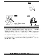
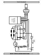
RED: +
BLACK: -


