background image

CONFIGURATION OF THE DEVICE SETTINGS   


51 

8027311 / V1-0/2022-04|SICK 

Subject to change without notice 

O P E R A T I N G   I N S T R U C T I O N S | TDC-E (Telematic Data Collector) 

7.3.7


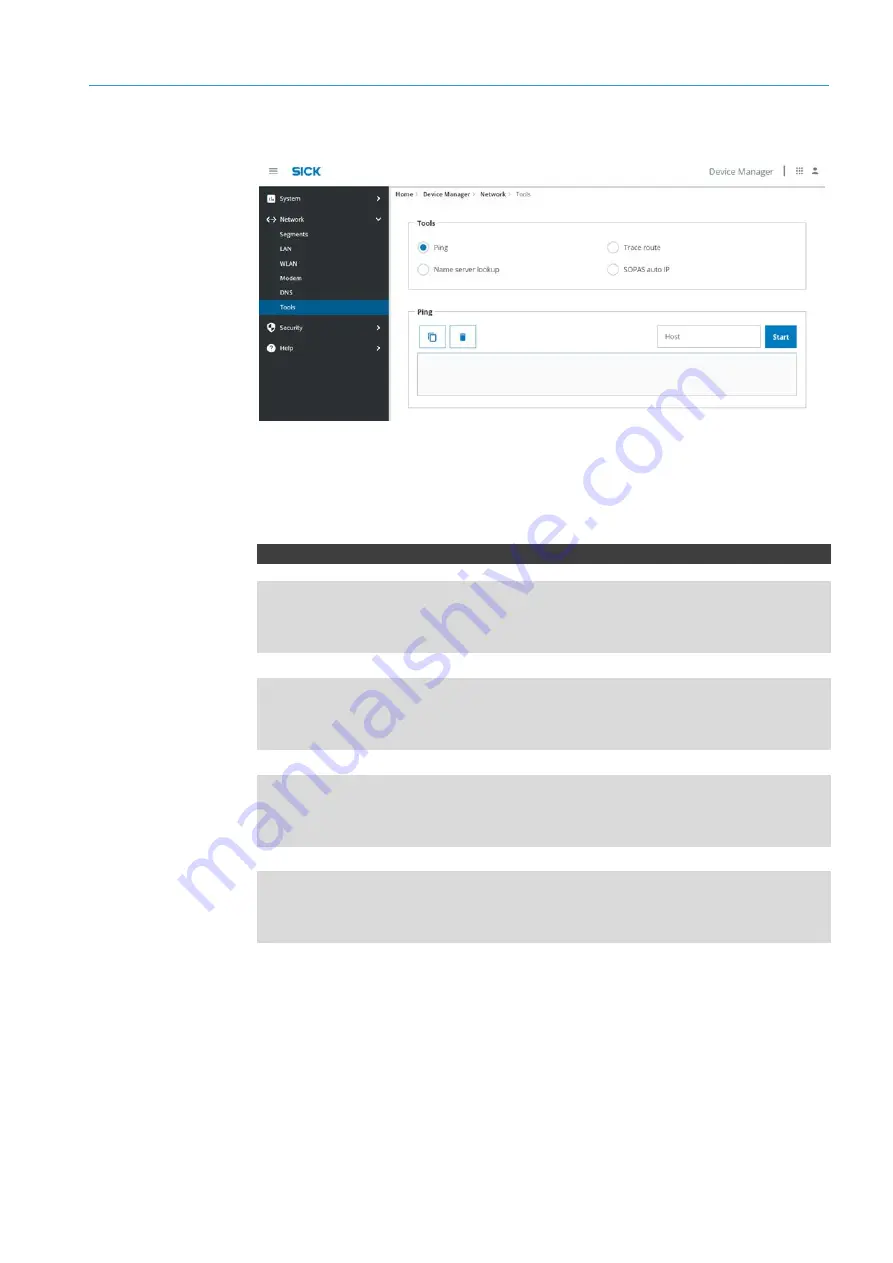
Tools 


The Device Manager has several tools to check the network connectivity of the devices 
connected to the TDC-E via Ethernet. 


Select the appropriate option and start the network search. 


REST API – settings 


PUT/tools/tracerout 

  "host": "string 


PUT/tools/ping 

  "host": "string 


PUT/tools/nslookup 

  "host": "string 


PUT/tools/sensors 

  "host": "string 


Checking the network 

connection 

REST API 

tools 

Summary of Contents for TDC-E

Page 1: ...OPERATING INSTRUCTIONS TDC E Telematic Data Collector Gateway systems ...

Page 2: ... by copyright The associated rights are reserved by SICK AG Reproduction of this document or parts of this document is only permissible within the limits of the legal provisions of copyright law Any modification abridgment or translation of this document is prohibited without the express written permission of SICK AG The trademarks mentioned in this document are the property of their respective ow...

Page 3: ...9 Mandatory symbols 11 3 System description 12 3 1 Scope of delivery 12 3 2 Data collection 14 3 3 Data processing 15 3 4 Data transmission 16 3 5 Status display on the TDC E 19 4 Mounting 20 4 1 Inserting SIM card 20 4 2 Mounting device 21 4 2 1 Mounting on a plate 21 4 2 2 Mounting on DIN mounting rails 22 5 Electrical installation 24 5 1 Connection overview of TDC E 25 5 2 Connector 26 5 3 Conn...

Page 4: ...erating request in Swagger 60 8 Configuring the connection settings 62 8 1 The Interface Manager 62 8 1 1 Starting Interface Manager 62 8 1 2 Interface Manager user interface 62 8 1 3 Authenticating access to interface parameters 64 8 1 4 Editing mode 64 8 2 Data collection interfaces 67 8 2 1 Motion sensor 67 8 2 2 Analog inputs 68 8 2 3 CAN interface 70 8 2 4 Digital inputs and outputs 72 8 2 5 ...

Page 5: ...ng Portainer 90 9 1 2 Creating initial user 90 9 1 3 Portainer user interface 91 9 2 Implementing application 92 9 3 User management in the Portainer 95 10 Maintenance and repair 96 10 1 Maintenance during operation 96 10 2 Replacing a TDC E 96 11 Technical data 97 11 1 Technical data 97 11 1 1 TDC E 97 11 1 2 Internal sensors 100 11 2 Dimensional drawings 101 11 3 TDC E pin assignments 102 12 Dis...

Page 6: ...ve this document Non compliance with notes and regulations Unauthorized mounting and installation Unauthorized technical and other changes Use of unauthorized spare parts wear and tear parts and accessories Unauthorized changes adjustments and or manipulations of software Failure to perform and document regular maintenance work The actual scope of delivery may differ from the features and illustra...

Page 7: ...ta network Controller Area Network serial bus system Long term evolution technical radio standard for digital radio telephony General Packet Radio Service the name of the packet based service for transmitting data over GSM networks Global Positioning System global navigation satellite system used for position determination Local Area Network Message Queue Telemetry Transport open messaging protoco...

Page 8: ...al company operating instructions at the installation location must be observed Storage of documents This document and other relevant technical documentation information Must be kept available for reference Must be handed over to new system operators new specialist personnel 1 6 Document conventions Instructions Result of action All measurement units used in this document are metric Subject to cha...

Page 9: ...o the cloud via the mobile network or via a WLAN connection In addition to the MQTT transmission protocol WebSocket is also supported In addition access to sensor data is possible via the integrated REST API interface NOTE Intended use also includes observance of this addendum in particular the safety notes as well as the repair and maintenance requirements 2 2 General safety notes Please read thi...

Page 10: ...ved Parts or components of the TDC E have been installed mounted or modified without authorization The software has been modified customized and or tampered with without authorization 2 5 RoHS Directive This product has been designed for specific applications in industrial environments according to Article 2 4 e RoHS 2011 65 EU and must therefore only be used in such environments The product is ne...

Page 11: ...h burns or electrical shock Only qualified specialist personnel are permitted to perform electrical work on the driver assistance system Before working on electrical components observe the five safety rules Disconnect Secure against being switched back on Ensure that there is no voltage Ground and short circuit Cover or enclose live parts in the vicinity 2 8 Warning symbols on the system component...

Page 12: ...ely Check that the delivery includes all components listed on the delivery note Fig 1 System components Legend 1 TDC E 2 WLAN antenna 3 LTE antenna 4 GPS antenna 5 Voltage supply cable 6 Quickstart Quantity Part no Description n 6070344 or 6079357 TDC E210xx n 6074432 WLAN antenna n 6077804 LTE antenna n 6067023 GPS antenna 3 m n 6068473 Voltage supply cable 0 9 m n 8022507 Quickstart guide includ...

Page 13: ...ector with 14 color coded wires with open ends length 90 cm Enables the connection of Voltage supply 2 wires Digital inputs and outputs Analog inputs 6068471 20 pin Micro Fit male connector with 20 color coded wires with open ends length 90 cm Enables the connection of Additional digital inputs and outputs RS 485 422 RS 232 SSI 1 wire serial interfaces CAN Tab 1 Additional connecting cables option...

Page 14: ...nsor data and sensor events When functioning in this capacity it offers all the standard interfaces required to integrate sensors machines and devices Digital analog CAN bus based serial and Ethernet based and other signals can be processed and aggregated These external sensor data are supplemented by data from the TDC E s factory installed movement position and temperature sensors The TDC E also ...

Page 15: ...ime and transmission costs Data processing is performed via applications that can be quickly implemented using the TDC E microservice architecture Node Red for example is a graphical development tool developed by IBM The software makes it possible to implement use cases for the Internet of Things with a simple modular principle The individual function blocks are related to each other by dragging c...

Page 16: ... hold the application itself but also all of the resources required by the application during runtime Thanks to the container technology the gateway system can be rapidly extended by adding customer specific applications 3 4 Data transmission Fig 6 Data transmission The sensor data can be transmitted to a customer server either via LAN WLAN or mobile radio Data is usually transferred via the MQTT ...

Page 17: ...r the connection is established which classifies the message hierarchically e g TDC E temperature sensor temperature Messages always consist of a topic and the message content Clients can subscribe to these topics with the MQTT message broker forwarding the received messages to the appropriate subscribers It is the TDC E that assumes the publisher role within the gateway system It uses the MQTT pr...

Page 18: ...transmission WebSocket is a TCP IP protocol that provides a constant open connection after an initial WebSocket handshake between a client and a WebSocket server A WebSocket server is nothing more than an application that monitors a port of a TCP IP server that follows a specific protocol The WebSocket server is installed by the customer The WebSocket server can actively use the open connection an...

Page 19: ...us display on the TDC E Status Green LED Yellow LED Red LED Authentication before booting ON OFF OFF Booting Fast flashing OFF OFF Device ready for operation Heartbeat flashing OFF OFF Restoration of backup Fast flashing Fast flashing OFF Device reset factory data or system reset Fast flashing Fast flashing OFF Software update Fast flashing Fast flashing OFF User defined via Interface Manager OFF ...

Page 20: ... connected to the voltage supply or close to the electrical installation so that the peripheral devices can be connected Select the mounting location so that the TDC E is protected from dirt and mechanical damage 4 1 Inserting SIM card The SIM card of the telecommunications provider must be inserted by the customer NOTE Only use M2M SIM cards without PIN CAUTION RISK OF DEVICE DAMAGE Only insert t...

Page 21: ...der with the contacts facing down Fig 12 Inserting SIM card into card holder Slide the plastic SIM cover back into place and lock it Reattach the housing cover to the bottom of the device and screw it tight Set up APN in configuration interface see section 7 3 5 modem 4 2 Mounting device 4 2 1 Mounting on a plate Use the mounting holes on the bottom of the device to mount it on a plate Fig 13 Moun...

Page 22: ...mounting rail bracket into the appropriate position and click it into place While clicking the bar out of one position and into another gently bend the top section of the base with your hands At the same time push the actuating bar forward This will avoid damaging the lug in the bar guide Fig 15 Mounting on a mounting rail Attaching the mounting rail bracket to the mounting rail Attach the mountin...

Page 23: ... N G I N S T R U C T I O N S TDC E Telematic Data Collector Fig 16 Mounting on a mounting rail Mounting the TDC E on the mounting rail bracket Place the TDC E on the bar and use the mounting holes on the mounting rail bracket to screw it on Mounting the TDC E on the mounting rail bracket ...

Page 24: ...essional training skills experience and knowledge of the relevant standards and provisions needed to work on electrical systems and to detect and avoid any potential dangers independently DANGER RISK OF INJURY DUE TO ELECTRICAL CURRENT The TDC E is connected to an external voltage source Touching live devices which may still be energized can lead to death burns or electrical shock Only qualified s...

Page 25: ...digital inputs and outputs RS 485 422 RS 232 SSI 1 wire serial interfaces CAN 3 Eth0 for connecting Ethernet capable sensors as well as connecting a configuration PC factory IP address 192 168 0 100 4 Eth1 for sending data via LAN factory IP address assigned by DHCP Fig 18 Connections at the back Legend 1 MCX female connector for connecting the GPS antenna 2 SMA female connector for connecting the...

Page 26: ...hernet capable machines or sensors can be connected to the TDC E with this connector variant In the case of the 14 pin Micro Fit male connector the cable assembly has 14 color coded open ended wires for connecting Voltage supply 2 wires Digital inputs and outputs Analog inputs In the case of the 20 pin Micro Fit male connector the cable assembly has 20 color coded open ended wires for connecting A...

Page 27: ...a permanent voltage supply If the TDC E is installed in a vehicle we recommend connecting it to the vehicle battery Plug the Micro Fit male connector at the end of the connecting cable into the 14 pin female connector on the TDC E Connect the TDC E to the voltage supply via the red and black wires of the connecting cable PWR PIN Wire color TDC E connection 14 Red VIN 9 V 36 V voltage supply 7 Blac...

Page 28: ...actory They must be screwed on before commissioning the devices Hold the device firmly with one hand Attach the antenna to the relevant SMA antenna connection on the TDC E Screw the antenna onto the device antenna connection by turning it clockwise Lay the connecting cable properly in the vehicle depending on the installation location of the antenna Plug the Cinch male connector at the end of the ...

Page 29: ...endently 6 1 Preparing for configuration Establish the voltage supply for the TDC E The operating system and Docker containers start up The device is ready for operation in the delivery state with five pre installed applications approx 180 seconds after it is started up If additional containers have been created by the customer the start up time will increase accordingly During a reboot via the TD...

Page 30: ...ation The gateway system is configured using three tools each with a web based interface The configuration tools are accessed via a central home page It is also possible to call them up via a respective URL When the configuration is called up for the first time a user must initially be created for the Device Manager The initial user automatically has administration rights 6 2 1 Creating initial us...

Page 31: ...ation interface opens It allows calling up of configuration tools as well as the user administration of the Device Manager Tool Function Device Manager Opens the interface for configuring the device settings User Management Opens the user administration Portainer Opens the web based interface for Management of Docker containers and Extension by customer specific applications Interface Manager Open...

Page 32: ...Legend 1 Menu bar 2 Navigator Contains the Device Manager functions in a tree structure 3 Display and input area depending on the selected function After starting the program this is the overview with the system settings Icon Meaning Display and hide navigator Opens the home page of the configuration interface Allows calling up of configuration tools as well as the user administration of the Devic...

Page 33: ...brief introduction to the Device Manager REST API library and the required authentication of access to the device data 7 2 1 System Provides an overview of the central device settings Device and host names of the TDC E can be changed The temperature sensor installed inside the TDC E supplies temperature values continuously so that any impending risk of the TDC E overheating can be detected in good...

Page 34: ...ange without notice REST API queries GET system resources GET system hostname GET system REST API settings PUT system deviceName string PUT system hostname hostName string PUT system power operation reboot 7 2 2 Maintenance Allows backup and restoration of the device configuration Allows the TDC E to be reset to factory settings REST API system Overview ...

Page 35: ... displayed in the list Select backup in the list Click on Apply Confirm safety note The selected backup will be installed Select Backup from the list Click on the download icon The backup file is downloaded Select backup file via network drive Click on Upload The selected backup will be uploaded to the TDC E and displayed in the list Install backup afterwards with Apply Backing up configuration on...

Page 36: ...ngs User information applications and data are deleted System All system settings are reset to default values User information applications and data are preserved Data Resets the data partition and Docker engine and deletes all user data REST API queries GET system backups GET system backups backup REST API settings PUT system backups POST system backups PUT system backups backup PUT system reset ...

Page 37: ... 3 Firmware Allows uploading of new firmware versions Select firmware file via network drive Click on Upload The selected file will be uploaded to the TDC E and displayed in the list Highlight the firmware version in the list and click Apply The firmware update is started REST API queries GET system updates REST API settings PUT system updates updateId Upload REST API firmware ...

Page 38: ... in case of network problems Activate NTP server Enter IP address or name of the NTP server and confirm via the plus icon The system time must not deviate more than 10 min from the system time of the computer which is connected to the TDC E If the deviation is greater access to the device is denied for safety reasons Configuration of an NTP server is recommended to avoid deviations over time REST ...

Page 39: ...ematic Data Collector 7 2 5 Logs All actions executed by the TDC E are logged The logs are stored until the next restart In the event of errors support can use the log as the basis for troubleshooting Icon Meaning Starts the download of log files Deletes all log files Updates the list of log files REST API queries GET system logs Overview REST API logs ...

Page 40: ...d as a network device and offers several network interfaces 2 x LAN 1 x WLAN 1 x modem The management of these interfaces is offered by the Device Manager In addition to the management of hardware network interfaces the Device Manager also enables the management of segments 7 3 1 Network The Device Manager allows management all network interfaces through the REST API endpoints grouped under networ...

Page 41: ...e There are no security measures e g firewall or restrictions between interfaces assigned to a bridge segment Any connection to interfaces belonging to a bridge segment is considered secure and the network operator must ensure that no security threats exist within that network connection A DHCP server can be operated via this segment This segment is used to add protections condition oriented firew...

Page 42: ...e case Sensors that access the Internet Used interfaces wlan eth1 Deactivated interfaces eth0 modem Segments 1 x bridge 1 x WAN with activated NAT Configuration Assign wlan to the WAN segment with NAT activated Check responsible network area together with network operator DHCP client vs manual IP and gateway setup Assign eth1 to the bridge segment Check with the responsible network operator DHCP c...

Page 43: ...operator DHCP client DHCP server or manual IP REST API queries GET networking segments bridges GET networking segments bridges bridge GET networking segments bridges bridge statistics GET networking segments GET networking segments wans GET networking segments wans wans GET networking segments wans wans statistics GET networking dhcp GET networking dhcp id REST API settings PUT networking segments...

Page 44: ...omainNameServers string range start string stop string leaseTime 0 7 3 3 LAN Activate the corresponding port in the respective line under Device State NOTE Configure port at Network Segments REST API queries GET networking lan GET networking lan lan GET networking lan lan details GET networking lan lan statistics REST API settings PUT networking lan lan segment string segmentType wan name string t...

Page 45: ...3 4 WLAN The TDC E provides an interface to wireless networks The interface can be configured in client mode or via an access point In the WLAN area activate the WLAN interface Select operating mode In the Client area under Periodic scan activate the network scan All available networks are listed Highlight the network in the list and click Connect Activating WLAN Client mode ...

Page 46: ...d NOTE If the connection is interrupted during operation the TDC E automatically attempts to reconnect via the Auto reconnect option When the device is restarted the WLAN will be connected automatically using the last SSID if there is no Ethernet connection available In the Access Point area configure the WLAN access point via SSID network key and the channel number NOTE Configure access point via...

Page 47: ...GET networking wlan wlan networks ssid REST API settings PUT networking wlan wlan networks state connected ssid string username string passphrase string reconnect true POST networking wlan wlan networks state connected ssid string username string passphrase string reconnect true PUT networking wlan wlan name string segment string segmentType wan enabled true state connected ap enabled true hidden ...

Page 48: ...works ssid ssid string username string passphrase string reconnect true 7 3 5 modem Configure the SIM card of the country specific telecommunications partner To do this fill in the fields in the Modem section accordingly and specify access point APN Access Point Name with user name and password Confirm access data with Apply In the Details section click Connect Entering GPRS data Activating connec...

Page 49: ...rking modem modem details GET networking modem modem apn GET networking modem modem statistics GET networking modem modem messages REST API settings GET networking modem modem segment string segmentType wan persist true name string type bridge enabled true state connected GET networking modem modem apn apn string user string password string dialString string POST networking modem modem sms message...

Page 50: ...configuration of a DNS server when passing data to a domain The DNS server DNS Dynamic Name Service is responsible for assigning the domain name to the IP address Specify domain name and IP address of the DNS server Click on the plus icon REST API queries GET networking dns GET networking dns status REST API settings PUT networking dns domainName string domainNameServers string REST API DNS ...

Page 51: ... 3 7 Tools The Device Manager has several tools to check the network connectivity of the devices connected to the TDC E via Ethernet Select the appropriate option and start the network search REST API settings PUT tools tracerout host string PUT tools ping host string PUT tools nslookup host string PUT tools sensors host string Checking the network connection REST API tools ...

Page 52: ... I O N S TDC E Telematic Data Collector Subject to change without notice 7 4 Security settings 7 4 1 Security Provides an overview of the security status of the system Docker and network connections 7 4 2 Certificates Allows uploading of security certificates for HTTPS connections or root certificates ...

Page 53: ...eys ca name GET security keys tls GET security keys system GET security keys device REST API settings POST security keys ca name string content string POST security keys tls certificate name string content string privateKey name string content string POST security keys system certificate name string content string privateKey name string content string POST security keys device name string content ...

Page 54: ... Collector Subject to change without notice 7 4 3 Logs The list contains the logs of all login operations and changes to user rights The logs are stored permanently in the TDC E Icon Meaning Starts the download of log files Deletes all log files Updates the list of log files REST API queries GET security log Overview REST API logs ...

Page 55: ... E in PDF format Device Management API Documentation Opens the REST API documentation for device configuration Alternative 192 168 0 100 18010 swagger SICK Support Portal Opens the login window to the SICK Support Portal SICK Device Information Opens the SICK homepage with information on TDC gateway systems 7 4 5 Licenses Provides information about all software components installed in the TDC E an...

Page 56: ...e users apply only to the Device Manager Log in to the Device Manager as a user with administrator rights Open user management via the central home page or the Device Manager menu bar The list of users is displayed Users with a check mark in the Enabled column are activated The initially created user was automatically assigned administration rights Click on the plus icon Enter name and contact det...

Page 57: ... admin and viewer role types The roles are assigned separately for the Device Manager client device manager and the login server client identity server Click on the plus sign in the user line In the Roles for user select one or more roles under Available and assign them with the arrow key Click on Save Two different roles are available each of type admin and viewer Users of type viewer have read o...

Page 58: ... click on the key icon of the Password column A window opens in which a new password can be assigned Click on Save To change roles or groups in the user row click the plus icon or the link in the Groups or Roles columns In the user line click the check mark in the Enabled column The user will be deactivated However it is still present in the user management Select user in the list To do this click...

Page 59: ... clipboard and used for configuring TDC E devices via command line NOTE If several TDC E devices are configured identically this way may be faster than connecting each TDC E individually and performing the configuration via the Device Manager user interface Click on Help in the navigation area Click on Device Management API Documentation Alternatively open the REST API library with http 192 168 0 ...

Page 60: ...et 1140b1c7 0644 49ee 8672 2d7bce196e7a Click Authorize Successful authentication is confirmed with the following message Confirm authentication with Close NOTE To log out open the Available authorizations window and click Logout 7 6 3 Generating request in Swagger The following example shows the generation of a PUT request to configure the device name In the list under System select the appropria...

Page 61: ...0 2022 04 SICK Subject to change without notice O P E R A T I N G I N S T R U C T I O N S TDC E Telematic Data Collector Enter parameter values here TDC_E Execute parameter values with Execute The response is output in the JSON structure Executing request ...

Page 62: ...ransmission via the MQTT or WebSocket interface Start the web browser on the configuration PC This browser must support HTML5 and WebGL Start configuration with http 192 168 0 100 On the home page click Interfaces NOTE Alternatively start Interface Manager with http 192 168 0 100 56000 8 1 2 Interface Manager user interface Legend 1 Menu bar with the central work areas 2 Toolbar with functions of ...

Page 63: ...ting status on the right side of the menu bar The user icon opens a menu with the following functions Function Meaning Reset Site Settings Sets all display settings zoom rotation in 3D displays table displays etc back to their default values Change User Log out current user and log in another user Logout Log out current user Language Select user language Icon Meaning Allows you to load a configura...

Page 64: ... with predefined user roles Click on the user icon Log in as a user with the Authorized Client or Service permissions using the password set up for this purpose see also section 8 6 User management in the Interface Manager 8 1 4 Editing mode The configuration of the connection parameters is done in editing mode NOTE Most parameters can be changed while the configuration is running Click the Edit s...

Page 65: ...f the device in the navigation tree Click on the gear icon of a connection type in the tree Click on the Parameters link NOTE Parameters that can be changed in the current site configuration with immediate effect are marked with a double arrow NOTE The Save Close button is grayed out and deactivated if authorization is not granted When you close the window you will be asked whether you want to sav...

Page 66: ...t notice Stopping and restarting the configuration after changing the parameters is recommended Click the Stop the current site configuration icon in the menu bar The configuration is unloaded The navigation tree is no longer displayed Then click on the Start current site configuration icon The start progress bar visualizes the progress Stopping site configuration ...

Page 67: ... sensor data can be retrieved and analyzed using Node RED or a customer application Open the Accelerometer connection parameter via the gear icon Activate motion sensor via the Enabled checkbox AccelerometerData WebSocket server URL ws 192 168 0 100 31768 ws tdce accelerometer data MQTT subscription directory tdce accelerometer data Results X 0 1393 Y 0 0478 Z 0 9782 AccelerometerChange WebSocket ...

Page 68: ... Activate the desired inputs and define the signal type in the Mode field The analog signal can be supplied as a voltage VOLTAGE entry or as an electrical current CURRENT entry Save configuration with Save Close The currently applied voltage or currently supplied electrical current is displayed under Value Analog signals can have any values in a given range for which conditions can be defined to t...

Page 69: ...nChange WebSocket server URL ws 192 168 0 100 31768 ws tdce analog inputs overcurrent protection MQTT subscription directory tdce analog inputs overcurrent protection activated AnalogInputsStateChange WebSocket server URL ws 192 168 0 100 31768 ws tdce analog inputs state MQTT subscription directory tdce analog inputs state Results AinName AIN_A PreviousState Inactive NewState Active AnalogInputsV...

Page 70: ...g vehicle downtime tracking routes and monitoring fuel data as well as collecting and processing the diagnostic data that is continuously recorded throughout a journey The system also handles customer specific road toll statements and analyzes journeys from a business perspective Open the CAN A or CAN B connection parameters via the gear icon Activate inputs via the Enabled checkbox and set the ba...

Page 71: ...28 Data 1 2 3 IsErrorFrame false IsExtendedFrameFormat false IsRemoteTransmissionRequest false CanBusBData WebSocket server URL ws 192 168 0 100 31768 ws tdce can b data MQTT subscription directory tdce can b out MQTT publish directory tdce can a in Results Id 128 Data 3 4 5 6 Results on CAN B CanBusName Can B Id 128 Data 3 4 5 6 IsErrorFrame false IsExtendedFrameFormat false IsRemoteTransmissionR...

Page 72: ...ear icon Activate digital inputs and outputs via the Enabled checkbox Save activation and reopen parameters Configure used interfaces DIO_A to DIO_F as digital inputs and outputs If necessary configure additional digital inputs and outputs Save configuration with Save Close DioDirectionChange WebSocket server URL ws 192 168 0 100 31768 ws tdce dio direction MQTT subscription directory tdce dio dir...

Page 73: ...cket server URL ws 192 168 0 100 31768 ws tdce dio states MQTT subscription directory tdce dio state out MQTT publish directory tdce dio state in Results DioName DIO_A Value 1 Direction Output DioName DIO_B Value 1 Results 2 responses from server DioName DIO_A Value 1 Direction Output AvailableDirections Input Output DioName DIO_B Value 1 Direction Output AvailableDirections Input Output ...

Page 74: ...connection parameters via the gear icon Activate GPS sensor via the Enabled checkbox GpsDataUpdate WebSocket server URL ws 192 168 0 100 31768 ws tdce gps data MQTT subscription directory tdce gps Results Latitude 0 0 Longitude 0 0 Time 0001 01 01T00 00 00 00 00 Altitude 0 0 SpeedKnots 0 0 SpeedMph 0 0 SpeedKmh 0 0 Course null Fix 0 NumberOfSatellites 0 GpsFixAvailable false Hdop 0 0 API GPS ...

Page 75: ...anagement via the Enabled checkbox On Off and Heartbeat periodic flashing modes are available for the yellow and red LEDs NOTE The conditions for the selected lighting behavior are defined e g via Node RED or a customer specific application LedStates WebSocket server URL ws 192 168 0 100 31768 ws tdce led states MQTT subscription directory tdce led out MQTT publish directory tdce led in Results Id...

Page 76: ...fter data was sent update every 2 seconds Id Yellow State On Id Red State On 8 2 7 Position sensor The position sensor magnetometer continuously detects coordinates and quantities for the X Y and Z axes values in milligauss mG The sensor has to be activated The sensor data can be retrieved and analyzed using Node RED or a customer application Open the Magnetometer connection parameter via the gear...

Page 77: ...tor MagnetometerData WebSocket server URL ws 192 168 0 100 31768 ws tdce magnetometer data MQTT subscription directory tdce magnetometer data Results X 369 0000 Y 1002 0000 Z 1186 0000 MagnetometerChange WebSocket server URL ws 192 168 0 100 31768 ws tdce magnetometer state MQTT subscription directory tdce magnetometer state Results PreviousState Opened NewState Closed ...

Page 78: ...nterface via the Enabled checkbox OneWireDataChange WebSocket server URL ws 192 168 0 100 31768 ws tdce onewire data MQTT subscription directory tdce onewire data OneWireDeviceInfoChange WebSocket server URL ws 192 168 0 100 31768 ws tdce onewire device info MQTT subscription directory tdce onewire deviceinfo OneWireStateChange WebSocket server URL ws 192 168 0 100 31768 ws tdce onewire state MQTT...

Page 79: ...puts via the Enabled checkbox and set the baud rate NOTE Only one of the two serial interfaces can be activated at a time Rs232Data WebSocket server URL ws 192 168 0 100 31768 ws tdce rs232 data MQTT subscription directory tdce rs232 out MQTT publish directory tdce rs232 in Results dGVzdA Rs4xxData WebSocket server URL ws 192 168 0 100 31768 ws tdce rs4xx data MQTT subscription directory tdce rs4x...

Page 80: ... E R A T I N G I N S T R U C T I O N S TDC E Telematic Data Collector Subject to change without notice Rs4xxStateChange WebSocket server URL ws 192 168 0 100 31768 ws tdce rs4xx state MQTT subscription directory tdce rs4xx state Results PreviousState Closed NewState Open ...

Page 81: ... via an RS422 interface Open the SSI connection parameter via the gear icon Activate interface via the Enabled checkbox NOTE Make sure that the RS422 interface is deactivated Otherwise an error is reported In the ClockFrequencyHz parameter store the specified clock rate The maximum achievable clock frequency depends on the length of cable and the driver components used The ClockPulseNumber paramet...

Page 82: ...the Interface Manager Open the WebSocket server WebSocket interface via the gear icon In the Path settings area all directories are configured in which sensor and device data are stored NOTE The directories do not have to be changed Confirm any changes made with Update In the Parameters area activate WebSocket interface via the Enabled checkbox Store connection information to the WebSocket server ...

Page 83: ... Interface Manager The access data for the MQTT message broker must be stored here Open the MQTT I O MQTT interface via the gear icon Activate the MQTT interface via the Enabled checkbox Store MQTT access data Parameter Meaning MqttClientId A unique ID that identifies the client If the parameter remains empty an ID is generated MqttHost MqttPort IP address and port of the MQTT message broker used ...

Page 84: ...ace Manager Appropriate authorizations are required Stop the running configuration in the Interface Manager To do this click the Stop the current site configuration icon in the menu bar Then click on Files Configuration Among other things the list contains the Rules file with the topics structure In the Rules file row click the gear icon The content of the XML file is displayed in the Content tab ...

Page 85: ... the Save the current site configuration icon in the toolbar The download dialog box of the browser opens right away Specify location The site configuration is saved in XML file format Select Site work area Click Load a configuration for starting or editing in the toolbar Select configuration file and load configuration 8 5 Downloading log files Select Files Logs from the menu bar Both log types a...

Page 86: ...municate what level of detail is needed to provide further assistance Log in to the Interface Manager with Authorized client permission or higher Switch to editing mode Click on the gear icon in the navigation area at the interface level Select the level of detail advised by Support in the DebugLogLevel parameter All system actions are now written to the log file of the Recorder type with the set ...

Page 87: ...lient User name Password Authorized client Client Has the following rights Changing IP addresses Changing interface parameters Service User name Password Service level May change all settings and states of the interface parameters Tab 6 User levels and authorizations Users with the Service authorization have access to all users They can create new users and delete existing users except the logged ...

Page 88: ...he previous field Confirm with Change Password Successful adaptation of the password is confirmed Return to the list of users using the arrow icon NOTE A password can be assigned for the Operator user which is delivered without a password by default with this function 8 6 2 Creating users Open the user management and click on Create User Enter user name NOTE The user name is case sensitive Note up...

Page 89: ... U C T I O N S TDC E Telematic Data Collector Logging in is done later with user name and password Fig 25 Login 8 6 3 Changing user password Users with Authorized Client and Operator authorization can only change their password in user administration Select Setup User Management from the menu bar Fig 26 Changing password Log in ...

Page 90: ...interface for managing the TDC E Start the web browser on the configuration PC Start configuration with http 192 168 0 100 On the home page click Portainer NOTE Alternatively start Portainer with http 192 168 0 100 9000 9 1 2 Creating initial user Portainer has its own user administration A user must be created when the program is called up for the first time Enter login name and password Click on...

Page 91: ...nge the password with my account and log out of the Portainer with log out 2 Navigation area Contains all functions of the Portainer in a tree structure 3 Display and input area depending on the selected function After program startup this is the overview line of the Docker Engine installed on the TDC E On the home page click in the Docker line The dashboard opens Among other things the number of ...

Page 92: ...ntainer technology The application can be conveniently created using a Docker composer file in YAML format This file can contain one or more containers and define their relationships among them Connect the TDC E to the Internet via WLAN or modem see the sections under 7 3 Network settings In the navigation pane click Volumes The list of Docker volumes already in use in TDC E is displayed Click Add...

Page 93: ...lector Click Stacks in the navigation pane The list of Docker stacks already in use in TDC E is displayed Click Add stack Assign names in the example node red stack Drag and drop Docker composer file into the web editor The file content is loaded into the editor Then click on Deploy the stack Creating Docker stack Uploading and deploying Docker composer file ...

Page 94: ...KER CONTAINER MANAGEMENT 94 8027311 V1 0 2022 04 SICK O P E R A T I N G I N S T R U C T I O N S TDC E Telematic Data Collector Subject to change without notice Node RED is now available via port 1880 Result ...

Page 95: ...navigation area The users already created are displayed under Users Create additional users To do this enter the user name and password under Add a new user If the user is to have administrator rights activate the Administrator switch Confirm input with Create user In the list of users click on the user name executed as a link Users can only change their password via the menu bar To do this click ...

Page 96: ...roper operation NOTE Depending on the operating environment remove dust from housing 10 2 Replacing a TDC E Defective devices must be replaced immediately The replacement device is configured by importing backup files created via the respective tools or by importing the user related applications via Docker stack Part no Device 6070344 or 6079357 TDC E210xx Tab 7 Part number of the TDC E replacemen...

Page 97: ... Enclosure rating IP20 acc to DIN EN 60529 Performance Sensor Acceleration sensor magnetometer thermometer Internal processor 1 GB DD3 dual core Cortex A7 with Cortex M4 co processor Internal memory 16 GB Operating system Linux4Microservices based on Linux Yocto Project 3 1 4 Dunfell Ecosystem Docker User interface TDC E Device Manager User Manager Interface Manager Data protocol MQTT REST API Web...

Page 98: ...and 2 4 GHz IEEE 802 11 b g n WPAN IEEE 802 15 1 IEEE 802 15 4 IEEE 802 15 3 Serial Electrical connection RS 232 RS 422 RS 485 SSI 1 wire Micro Fit 20 pin CAN bus Data transmission rate Log Electrical connection 2 1 Mbit s adjustable J1939 CANopen Micro Fit 20 pin USB Electrical connection USB2 0 USB 2 0 A male connector Inputs outputs I O 6 analog inputs configurable current and voltage 6 digital...

Page 99: ...Product safety EN 62311 2008 Radio equipment approval RED General notes Description The gateway networks sensors machines and IIoT platforms for collecting and preprocessing local sensor and process data Scope of delivery TDC E210GC and mobile communication without flow of data including TDC connecting cables and operating instructions Classifications ECl ss 6 0 19179090 ECl ss 6 2 19179090 ECl ss...

Page 100: ...5 m CEP 50 24 hours static 130 dBm 6 SVs Tab 9 GPS accuracy Motion sensor accuracy Full scale area 2 g 4 g 8 g Resolution Up to 0 244 mg Update rate 1 56 Hz to 400 Hz Tab 10 Motion sensor accuracy Position sensor accuracy Full scale area 12 000 mGa Resolution Up to 1 mag Update rate 1 56 Hz to 400 Hz Tab 11 Position sensor accuracy Thermometer accuracy Resolution 0 5 C Accuracy 0 5 C from 20 C to ...

Page 101: ...HNICAL DATA 11 101 8027311 V1 0 2022 04 SICK Subject to change without notice O P E R A T I N G I N S T R U C T I O N S TDC E Telematic Data Collector 11 2 Dimensional drawings Fig 27 Dimensional drawings ...

Page 102: ... 36 V DC 7 Black GND Ground DIO 13 Yellow DIO_A Digital input output Channel A 6 White DIO_B Digital input output Channel B 12 Blue DIO_C Digital input output Channel C 5 Pink DIO_D Digital input output Channel D 11 Gray DIO_E Digital input output Channel E 4 Violet DIO_F Digital input output Channel F AIN 10 White yellow AIN_A Analog input Channel A 3 White green AIN_B Analog input Channel B 9 Wh...

Page 103: ...X Cable for receiving data 15 White yellow CTS Clear to send 5 White gray RTS Request to send RS 485 RS 422 SSI 14 Violet Y CLK RS 485 422 SSI data cable 4 White purple Z CLK RS 485 422 SSI data cable 13 Pink A DATA RS 485 422 SSI data cable 3 White black B DATA RS 485 422 SSI data cable CAN A 12 White CANH_A CAN high Channel A 2 Blue CANL_A CAN low Channel A CAN B 11 White green CANH_B CAN high C...

Page 104: ... electronic devices In accordance with international directives and regulations batteries accumulators and electrical or electronic devices must not be disposed of with household waste The owner is obligated to dispose of the devices at the end of their service life via the appropriate public disposal points This icon on the product packaging or in this document indicates that a product is covered...

Page 105: ...p Malaysia Phone 603 8080 7425 E Mail enquiry my sick com Mexico Phone 52 472 748 9451 E Mail mario garcia sick com Netherlands Phone 31 0 30 229 25 44 E Mail info sick nl New Zealand Phone 64 9 415 0459 0800 222 278 tollfree E Mail sales sick co nz Norway Phone 47 67 81 50 00 E Mail sick sick no Poland Phone 48 22 539 41 00 E Mail info sick pl Romania Phone 40 356 17 11 20 E Mail office sick ro R...

Reviews: