The current value of the time stamp in milliseconds can be read out via Index 4437.
The time stamp always starts at 0 ms when the sensor is reset/restarted. The time
stamp can be written after the sensor is started to synchronize it with an absolute time
source.
NOTE
The length of the time stamp is 64 bits and cannot be processed by some controllers.
The 5 strongest shock events are stored permanently. Each newly added shock is
sorted according to its strength. If a new shock is added, the shock with the lowest
acceleration is overwritten accordingly.
For all stored shock events, the maximum acceleration and the time stamp are availa‐
ble, for the strongest shock also the course of time of the shock.
Readout of the history of the shock data (Index 4439 and 4442)
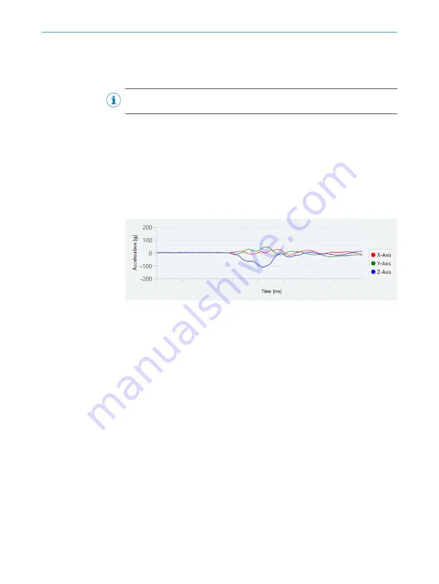
For the shock that occurred last and the shock with the strongest acceleration, the
course of the acceleration values in the period from 5 ms before to 21 ms after the
shock is available. As shown in
, all 3 axes can be viewed over time.
Figure 23: Shock data over time
There are 170 acceleration values available for each axis, which can be read out in two
blocks of 85 values each as follows:
1.
Set the desired axis via Index 4439 (last shock) or 4442 (strongest shock) using
Subindex 2.
2.
Select the first data block (block 0) via Subindex 1.
3.
Read the first 85 values for the axis via Index 4440 (last shock) or 4443 (stron‐
gest shock).
4.
After that the second block (block 1) can be selected and read out via the follow‐
ing index.
This procedure can be repeated for the other two axes. The values are sampled at a
rate of 6,400 Hz.
Both the permanently stored shock data and the shock data for the last shock that
occurred can be reset by writing value 1 to Index 4448.
9.6
Configuration of digital outputs
The sensor has pin 2 and pin 4 as digital inputs/outputs. Pin 2 can be configured as
a digital output or external input. When configured as an external input, the input value
can either be used as an external trigger or its value can be linked to logic values from
the sensor. In applications where IO-Link is not used, pin 4 can also be used as a digital
output. Pin 2 of the sensor can be parameterized via Index 121 as external input for the
A00 logic, as switching signal and as trigger signal (
see "Trigger (Index 4474-4475)",
).
9
OPERATION
44
O P E R A T I N G I N S T R U C T I O N S | MPB10
8028041/2022-08-16 | SICK
Subject to change without notice


