


•
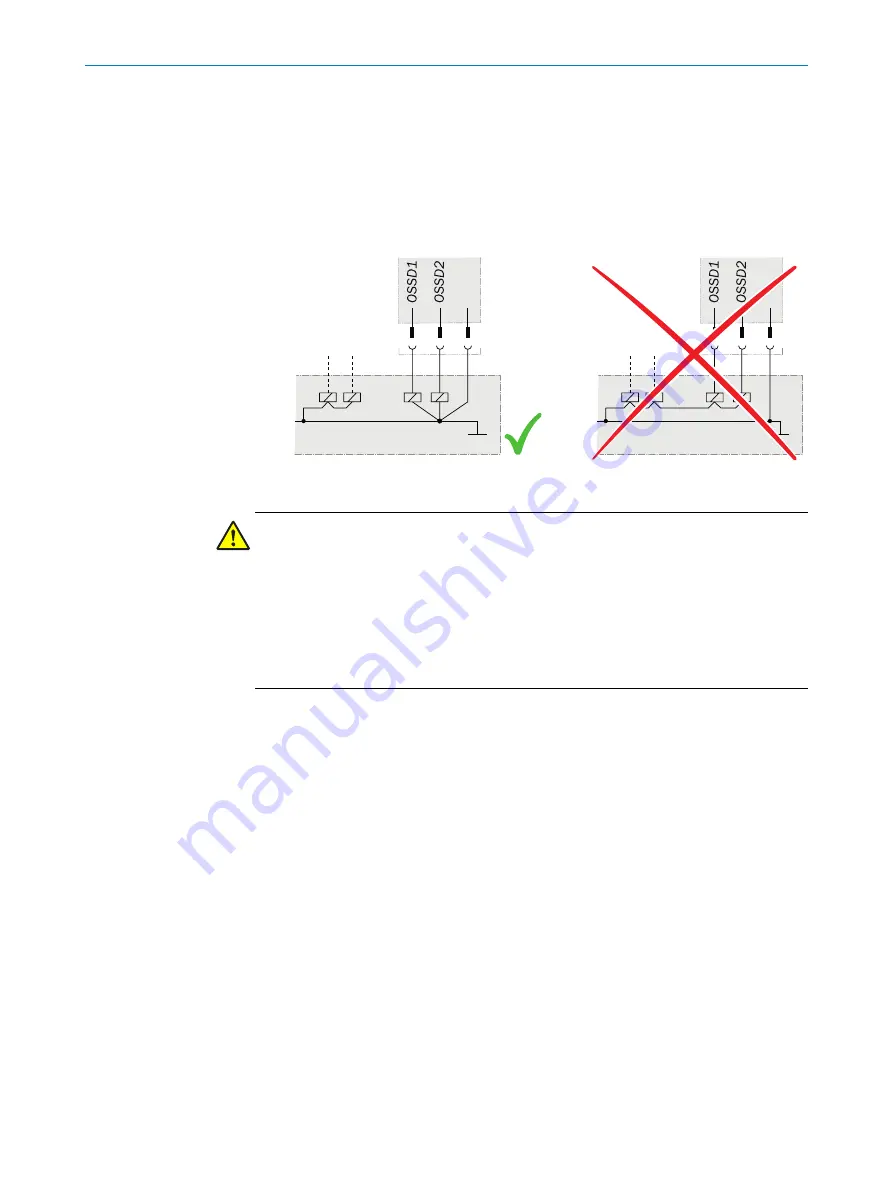
Prevent the formation of a potential difference between the load and the protec‐
tive device. If you connect loads to the OSSDs (safety outputs) that then also
switch if controlled with negative voltage (e.g., electro-mechanical contactor with‐
out reverse polarity protection diode), you must connect the 0 V connections of
these loads and those of the corresponding protective device individually and
directly to the same 0 V terminal strip. In the event of a fault, this is the only way to
ensure that there can be no potential difference between the 0 V connections of
the loads and those of the corresponding protective device.
Figure 5: No potential difference between load and protective device
DANGER
Hazard due to lack of effectiveness of the protective device
In the case of non-compliance, it is possible that the dangerous state of the machine
may not be stopped or not stopped in a timely manner.
Downstream contactors must be positively guided and monitored depending on applic‐
able national regulations or required reliability of the safety function.
b
Make sure that downstream contactors are monitored (external device monitoring,
EDM).
Requirements for the electrical control of the machine
•
Use the control without test pulses. The safety switch is self-testing.
•
The safety switch tests the OSSDs at regular intervals. To do this, it switches each
OSSD briefly (for max. 1 ms) to the OFF state and checks whether this channel is
voltage-free during this time.
Make sure that the machine’s control does not react to these test pulses and the
machine does not switch off.
•
The inputs of a connected evaluation unit must be positive-switching (PNP), as the
two outputs of the safety switch send a level of the supply voltage in the switched-
on state.
The OSSDs are short-circuit protected to 24 V DC and 0 V. When the actuator is in the
sensor’s response range, the OSSDs signal the ON state with the HIGH signal level (non-
isolated). If the actuator is removed from the sensor’s response range or there is a
device fault, the OSSDs signal the OFF state with the LOW signal level.
The safety switch complies with the regulations for electromagnetic compatibility (EMC)
for the industrial sector (Radio Safety Class A). Radio interference cannot be ruled out
when used in residential areas.
PROJECT PLANNING
4
8020169/ZJN1/2018-03-21 | SICK
O P E R A T I N G I N S T R U C T I O N S | MLP1
15
Subject to change without notice


