background image

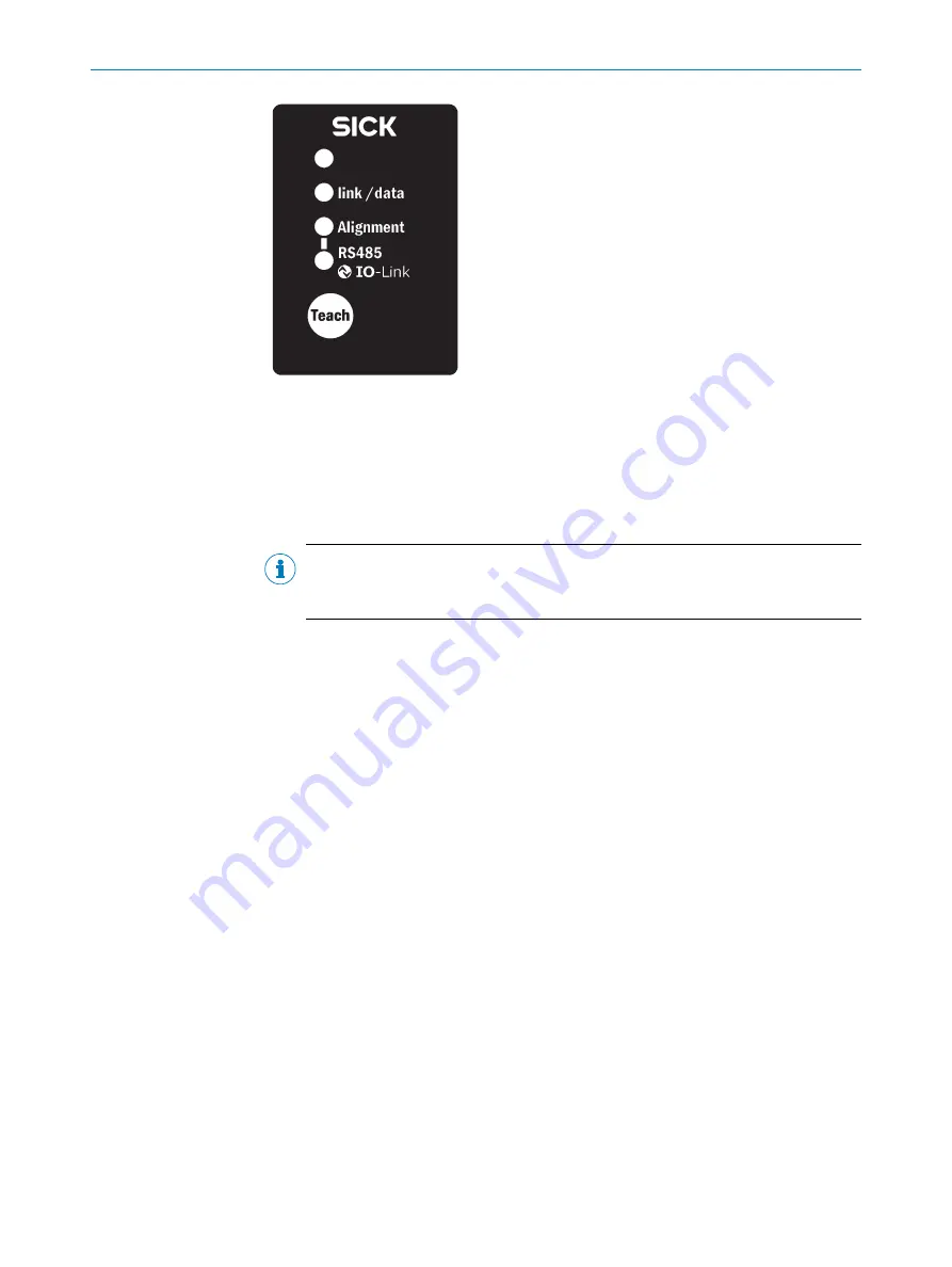
Figure 43: Control panel of the MLG-2 Pro

Ö

 3 Hz yellow

The yellow LED on the front flashes rapidly.

b

Improve the alignment of the MLG-2.

o

When the yellow LED and the 

Alignment

 LED go out, the MLG-2 is optimally aligned.

NOTE

With the MLG-2 Pro, SOPAS ET will help you to align the device and teach-in the
sensitivity (

see "Teach-in", page 90

).

b

Now fix the position of the sender and receiver.

Teach-in

b

Press the 

Teach

 pushbutton (< 1 s).

3)

Ö

 1 Hz yellow

The yellow LED on the front and the 

Alignment

 LED flash slowly.

If the teach-in process is successful, the yellow LED on the front and the 

Alignment

 LED

go out. The MLG-2 is operational.

If the teach-in process is unsuccessful, the Alignment and RS-485/IO-Link LEDs flash
rapidly, as does the red LED on the front of the device.

b

Check that the MLG-2 is correctly aligned, that the front screens are clean and
that there are no objects located in the light path.

b

Then carry out the teach-in process again.

3)

On the MLG-2 Pro, the teach-in process can also be triggered via SOPAS ET, IO-Link, the integrated web server or the Teach input.

COMMISSIONING

52

O P E R A T I N G   I N S T R U C T I O N S | MLG-2 Pro

8017460.ZIK1/2017-02-13 | SICK

Subject to change without notice

Summary of Contents for MLG-2 Pro

Page 1: ...O P E R A T I N G I N S T R U C T I O N S MLG 2 Pro Measuring automation light grid...

Page 2: ...ble within the limits of the legal determination of Copyright Law Any modifica tion abridgment or translation of this document is prohibited without the express writ ten permission of SICK AG The trad...

Page 3: ...MLG 2 16 3 4 4 Beam separations and monitoring height 16 3 4 5 Teach in 17 3 4 6 Beam blanking 18 3 4 7 Sensing ranges 19 3 5 Scan time 19 3 5 1 Response time minimum presence time and reproducibil i...

Page 4: ...ngles 38 4 2 4 Minimum distance from reflective surfaces 39 4 3 Mounting procedure 40 4 3 1 Mounting the QuickFix bracket 40 4 3 2 Mounting the FlexFix bracket 41 5 Electrical installation 43 5 1 MLG2...

Page 5: ...g function 85 7 8 Data output via the interfaces 87 7 8 1 RS485 Data transmission format 87 7 8 2 RS485 Transmission mode 88 7 8 3 RS485 and IO Link Data transmission content 88 7 9 Teach in 90 7 10 P...

Page 6: ...nse time and minimum presence time during high speed scan with 2 5 mm resolution 123 13 2 3 Response time and minimum presence time during high speed scan with up to 3 5 m sensing range 123 13 2 4 Res...

Page 7: ...machine carry out its commissioning or who are in charge of mainte nance 1 4 Information depth These operating instructions contain information about the MLG 2 measuring automa tion light grid on the...

Page 8: ...ked BNM Beam Number x Made CBB Central Beam Blocked CBM Central Beam Made FBB First Beam Blocked FBM First Beam Made IDI Inner Dimension LBB Last Beam Blocked LBM Last Beam Made MDA Minimum Detectable...

Page 9: ...measuring device which is manufac tured according to the recognized industrial regulations and which meets the quality requirements stipulated in ISO 9001 2008 as well as those relating to environmen...

Page 10: ...afety guidelines The operating instructions must always be available and must be followed Unqualified personnel must stay away from the system during installation and maintenance The system must be in...

Page 11: ...t of the M12 5 pin or M12 8 pin male connector Diagram of the M12 4 pin female connector Pin assignment of the M12 4 pin female connector 3 2 MLG 2 Pro type code Example MLG 2 with 5 mm beam separatio...

Page 12: ...50 445 445 440 440 425 420 400 595 595 590 580 575 570 550 745 745 740 740 725 720 700 895 895 890 880 875 870 850 1045 1045 1040 1040 1025 1020 1000 1195 1195 1190 1180 1175 1170 1150 1345 1340 1340...

Page 13: ...m 5 mm 08 8 5 m 5 mm Table 6 Sensing range and minimum detectable object length 3 2 4 MLG 2 Pro preconfigurations Position 16 17 QA1 QA2 Q1 C Q2 IN1 Teach in 01 NBB LBB Object detection Teach in Stan...

Page 14: ...f MLG 2 Pro with I O combination I see table 5 page 13 Position 16 17 Q1 C Q2 IN1 Q3 Q4 IN2 Teach in 01 Object detection Teach in Object detec tion Object detec tion Standard operating mode 02 Object...

Page 15: ...al sender elements LEDs and actuation electronics The receiver consists of receiver optics several receiver elements photodi odes and evaluation electronics 3 4 1 MLG 2 Pro device components Figure 3...

Page 16: ...ing range of the light grid The monitoring height is determined by the beam separation and the number of beams The sensing range of the light grid is the distance between sender and receiver 3 4 3 Syn...

Page 17: ...individually adjusted for the sensing range and the ambient conditions After teach in has been completed it must be ensured that the setup is no longer changed otherwise another teach in will have to...

Page 18: ...ing teach in quality and process quality data The quality performance indicators can be retrieved in various ways SOPAS ET RS485 IO Link Integrated web server switching outputs Analog outputs 3 4 6 Be...

Page 19: ...iting range which goes beyond the operating range Operating range Limiting range 2 m 2 8 m 5 m 7 m 8 5 m 12 m Table 11 Limiting range Operation within the limiting range requires the following conditi...

Page 20: ...The minimum presence time is max 2 the scan time The repeat accuracy of a measurement result reproducibility is the amount of time by which an object detection can differ from a previous or subsequen...

Page 21: ...nt on the number of beams Beyond a certain number of beams the scan time is reduced because it is possible to use the high speed scan Number of beams Scan time 1 2 Figure 11 Scan time in relation to t...

Page 22: ...ved by the MLG 2 depends on the beam separation 3 6 1 Minimum detectable object with parallel beam function In order for an object to be detected continuously it must completely cover at least one bea...

Page 23: ...the detection area it must have a certain length 1 Figure 13 Minimum detectable object length 1 Minimum detectable object NOTE For moving objects the minimum detectable object length also depends on t...

Page 24: ...plications height classification object recognition etc the results of the paral lel beam function are used Use of the cross beam function increases the response time With the cross beam function a mi...

Page 25: ...Beam diameter 2 Object is reliably detected meets requirements of minimum detectable object size Beam separation Minimum detectable object stationary object 1 2 5 mm 2 5 mm 5 mm 5 mm 10 mm 10 mm 20 m...

Page 26: ...reserves Setting the operating reserve high makes the MLG 2 very resistant to contamination However it is not possible to activate high measurement accuracy in this case NOTE In order to achieve a hi...

Page 27: ...ean PET bottles clear glass thin and clear films e g cellophane household plastic film plastic wrapping Approx 15 signal attenuation Clean clear glass bottles thick films film and wrapping folded mult...

Page 28: ...g a data message Figure 16 Status of the beams 0 1 1 1 1 0 0 0 0 0 0 1 1 1 1 0 0 0 0 0 0 1 1 1 1 0 0 0 0 0 0 0 Table 17 Example status for an MLG 2 with 32 beams 0 Beam clear 1 Beam blocked The data m...

Page 29: ...ming can be used to carry out complex applications with variables operands and functions in SOPAS ET 1st option The beam functions are directly linked with the outputs Example Q1 Total number of beams...

Page 30: ...t measurement last beam blocked C FBB Object height measurement first beam blocked C ODI Measurement of the outer dimension C IDI Measurement of the inner dimension C CBB Measurement of the object pos...

Page 31: ...e sender 1 Yellow 2 Red 3 Green 3 10 2 Receiver LEDs The receiver has three LEDs on its front and a control panel with LEDs and membrane keys on its rear The LEDs and the control panel are located on...

Page 32: ...r the MLG 2 can be started by pressing the Teach button The MLG 2 control panel can be locked to prevent incorrect operation The lock can be activated and deactivated via SOPAS ET IO Link or via the p...

Page 33: ...he sender The test input can be used to switch off the sender This simulates a complete blocking of the beams This makes it possible to test the behavior of the switching or analog out puts that have...

Page 34: ...applications Figure 24 Volume measurement Figure 25 Contour measurement Table 22 Application examples for the MLG 2 3 PRODUCT DESCRIPTION 34 O P E R A T I N G I N S T R U C T I O N S MLG 2 Pro 8017460...

Page 35: ...cted are shiny Therefore when mounting two MLG 2s close to one another their light beams should be oriented in opposite directions 4 2 1 Mounting with light in opposite directions Figure 26 Placement...

Page 36: ...oriented in the same direc tion a minimum distance must be maintained between the MLG 2s The minimum dis tance increases as the distance between the sender and receiver increases and is dependent on...

Page 37: ...6 0 m 8 0 m Y X Operating range Minimum distance MLG 2 with 5 m and 8 5 m sensing range Figure 28 Graph distances when light is in the same direction MOUNTING 4 8017460 ZIK1 2017 02 13 SICK O P E R A...

Page 38: ...aph distances when light is in the same direction XZ 4 2 3 Placement of two light grids at right angles Light grids are placed at right angles for volume detection or operator guidance for example Fig...

Page 39: ...reflective surfaces a minimum distance must be maintained between the reflective surface and the light beams to ensure reliable operation This minimum distance depends on the distance between sender...

Page 40: ...amage the bracket while lower torques do not provide adequate fixation to prevent the MLG 2 from moving in the event of vibrations When mounting make sure that sender and receiver are aligned correctl...

Page 41: ...ppropriate screw length to prevent any risk of injury from an overrun Figure 33 Mount QuickFix bracket to a profile frame Mount QuickFix bracket to the back of a device column NOTE The QuickFix bracke...

Page 42: ...or receiver into the FlexFix brackets After mounting the FlexFix brackets screw the sender or receiver into the FlexFix brack ets from the front Then align the sender and receiver NOTE The MLG 2 can...

Page 43: ...nchronization cable wherever possible CAUTION These devices must be fused with a 1 A 30 V DC fuse Wire cross section Maximum amperage for over current protection AWG mm2 20 0 52 5 22 0 32 3 24 0 20 2...

Page 44: ...g outputs Q M12 8 pin Acoded Male connector Pin Signal Meaning Color 1 L 24 V supply voltage Brown 2 Sync_A Synchronization White 3 M GND supply voltage Blue 4 Q1 C Switching output 1 with IO Link int...

Page 45: ...I O connection with RS485 interface M12 8 pin Acoded Male connector Pin Signal Meaning Color 1 L 24 V supply voltage Brown 2 Sync_A Synchronization White 3 M GND supply voltage Blue 4 Q1 C Switching o...

Page 46: ...G For the MLG 2 Pro there are three T distributors available which are used to connect the sender and receiver to one another as well as provide connection facilities for the following options Connect...

Page 47: ...L 24 V supply voltage 2 Test_In Test input 3 M GND supply voltage 4 Q1 C Switching output 1 with IO Link interface 5 Not connected Not connected 6 Q2 IN1 Switching output 2 or Switching input 1 7 Q3 Q...

Page 48: ...Link master Male connector Pin Signal Meaning 1 L 24 V supply voltage 2 Q3 QA1 RS485_A Switching output 3 or Analog output 1 or RS 485 interface 3 M GND supply voltage 4 Q1 C Switching output 1 with...

Page 49: ...L 24 V supply voltage 3 Not connected Not connected 4 Q2 IN1 Switching output 2 or Switching input 11 2 5 Q1 Switching output 1 6 Q3 QA1 RS485_A Switching output 3 or Analog output 1 or RS 485 interf...

Page 50: ...t be clear Alignment with the QuickFix bracket You have the following adjustment options with the QuickFix bracket Adjust vertically H Figure 40 Alignment with the QuickFix bracket Alignment with the...

Page 51: ...makes the best possible settings for the input sensitivity and ensures that the alignment aid shows the most helpful values Figure 42 Rotate the receiver once 6 2 1 MLG 2 Pro The yellow LED on the fro...

Page 52: ...ly If the teach in process is successful the yellow LED on the front and the Alignment LED go out The MLG 2 is operational If the teach in process is unsuccessful the Alignment and RS 485 IO Link LEDs...

Page 53: ...re the MLG 2 7 1 2 Device selection A SOPAS Device Description SDD is required in order to configure the MLG 2 Detecting a connected device When an MLG 2 is connected to the PC notebook via Ethernet t...

Page 54: ...lass PET etc Dust and sunlight resistant For applications when there is a large amount of dust in the environment or a high level of solar radiation NOTE When the operating mode is changed a new teach...

Page 55: ...ailable options in expandable menus 7 2 1 System boundaries status and interfaces System boundaries Figure 46 Display of the system boundaries Under System boundaries SOPAS ET displays the reproducibi...

Page 56: ...Only the neces sary adjustments for the MLG 2 will be offered according to the choice of applica tion Recommendation Use this wizard for the initial configuration of a device The separate adjustments...

Page 57: ...new I O tab An overview of the basic functions and the run length code values are also available in the new tab Process quality Figure 49 Display of the process quality SOPAS ET shows the process qua...

Page 58: ...see Beam functions page 107 The current values for the run length code Figure 50 Basic functions and status of the output Status inputs outputs Under Status inputs outputs SOPAS ET shows the status of...

Page 59: ...the mouse Turquoise Configured tolerance You can use the context menu to perform certain actions with the selected beams Context menu Combining beams into zones b Select multiple consecutive beams b I...

Page 60: ...ze may vary positively or negatively by the number of tolerance beams set see Object recognition page 69 Context menu Using beams for height classification b Select a beam b In the context menu select...

Page 61: ...select several beams b In the context menu select the command Blank all selected beams Figure 56 Blanking beams In the example beams 13 14 and 15 are selected and blanked They are shown in gray and ex...

Page 62: ...lay of the MLG 2 rotated Repeat this process until you are happy with how the image appears 7 2 4 Expandable menus The expandable menus on the right hand side help you to configure the MLG 2 7 CONFIGU...

Page 63: ...utputs You will see the response of the outputs immediately in the status indicator Figure 61 Effect of the output configuration on the status indicator Configuring the performance options When the ML...

Page 64: ...area contains the following information Hardware version Software version IO Link The IO Link area contains the following information IO Link revision Minimum cycle time in ms Switching operation supp...

Page 65: ...Not defined the connection has not been activated either as an input or an output NOTE If you change the configuration of a connection all of the functions that have been con figured for the input e g...

Page 66: ...is active A teach in is required All functions become available again only after a suc cessful teach in process The Reset command sets the MLG 2 back to the factory settings Ethernet In the Ethernet a...

Page 67: ...lly The output becomes active when an object is larger than the defined object The device checks therefore whether an object exceeds a certain height b Place or hang the object in the detection area o...

Page 68: ...as the top beam or reaches beyond this beam Object is less than or equal to n beams The output becomes active when an object covers the beam defined as the top beam or reaches less beams Object is equ...

Page 69: ...ion The sizes can be further adjusted afterward Manual configuration In the simulation you can determine the size of the object s by selecting correspond ing beams Figure 68 Beams highlighted in color...

Page 70: ...the detection area The object is allowed to move within the detection area This also applies to multiple objects e g the feet of a pallet Figure 70 Object recognition dynamic 1 Output not switched 2...

Page 71: ...ion with turquoise beams Output settings General options for switching outputs see Advanced settings for the outputs page 84 7 4 3 Object detection object width A switching output switches when an obj...

Page 72: ...tput becomes active if the configured number of beams or less were cov ered n object is equal to n beams The output becomes active if precisely the configured number of beams were cov ered The object...

Page 73: ...tion hole size A switching output switches when an object with a hole of a particular size is present in the detection area A corresponding setting is configured which requires a certain number of bea...

Page 74: ...r less were made n hole is equal to n beams The output becomes active if precisely the configured number of beams were made The hole size that has been set is shown in the Simulation area It can be ch...

Page 75: ...5 Outside inside dimension A switching output switches when an object with a particular outside or inside dimen sion is detected NOTE If there are several objects in the detection area the largest ob...

Page 76: ...ject dimension is equal to n beams The output becomes active if precisely the configured number of beams was blocked made A particular number of beams is configured for the outside or inside dimension...

Page 77: ...The object center is greater than or equal to the position of beam number n Figure 81 Classification of the object position greater than or equal to object center 1 Made beam 2 Blocked beam 3 Configu...

Page 78: ...switches when the center of a hole is located on the beam config ured as the hole position NOTE If there are several holes in the detection area the central beam of the largest hole determines the ho...

Page 79: ...ess than or equal to hole center 1 Made beam 2 Blocked beam 3 Configured beam The hole center is equal to the position of beam number n The center of the hole is located exactly on the configured beam...

Page 80: ...in process Hardware error The output is activated when an error occurs with the hardware Possible cause LED defective receiver element defective etc Activate Qn if the teach in quality falls below The...

Page 81: ...m 1 LBB The output provides a current which is analogous to the height of the highest blocked beam Height measurement starting at the last beam LBB The output provides a current which is analogous to...

Page 82: ...4 Measuring the outer or inner dimension An analog output changes its output current analogously to the outer or inner dimen sion of an object The output displays the outer or inner dimension of an ob...

Page 83: ...alog output changes its output current analogously to the position of the hole cen ter in the detection area Figure 95 Measurement of the hole position Output settings General options for analog outpu...

Page 84: ...to the minimum pulse width 1 Analog outputs For analog outputs select one of the following settings 4 mA 20 mA The output current increases with the number of the highest lowest blocked beam If the m...

Page 85: ...Zone 1 2 e g Zone 2 NBB Zone 2 LBB Zone 2 FBB Zone 2 CBB Zone 2 or NCBB Zone 2 3 e g Zone 3 NBB Zone 3 LBB Zone 3 FBB Zone 3 CBB Zone 3 or NCBB Zone 3 Configuring the Zone measuring function using SO...

Page 86: ...expandable menu b In the Zone selection area define the Zone no First beam and Last beam for the zone b Activate the zone you wish to assign to an output Configuring an output b Click the Digital out...

Page 87: ...of blocked beams in Zone 1 7 8 Data output via the interfaces The expandable Interfaces menu is only displayed if the device in use has a data inter face RS485 and or IO Link 7 8 1 RS485 Data transmi...

Page 88: ...he light grid responds with a data string if the selected character is received Interval Sends the data using the specified interval Beam status change with interval Sends the data only when the beam...

Page 89: ...lable functions window and click on the button Figure 102 Selected functions The function is transferred to the Selected functions window Figure 103 Sorting selected functions b Select a function in t...

Page 90: ...ted for the sensing range and the ambient conditions A teach in process must be carried out when commissioning when changing operating mode or performance options and at regular intervals in general b...

Page 91: ...h in when switching on device option the teach in process will be performed every time you switch the device on Teach in quality Figure 108 Teach in quality The teach in quality indicates how successf...

Page 92: ...teach in process b Click Blank all made beams The made beams will not be taken into account in the measurement How to blank made beams Figure 110 Example of blanking made beams 1 Made beams 2 Blocked...

Page 93: ...in Transparent operating mode minimum detectable absorption of an object Figure 111 Performance options for Standard operating mode and Dust and sunlight resistant operating mode CONFIGURATION WITH SO...

Page 94: ...ocess and to apply the modified per formance options The system boundaries resulting from the performance options are displayed on the left in SOPAS ET see System boundaries status and interfaces page...

Page 95: ...ottles clear glass thin and clear films e g cellophane household plastic film plastic wrapping Approx 15 signal attenuation clean clear glass bottles thick films film and wrapping folded multiple time...

Page 96: ...s beam measuring function In the Cross beam switching option the crossed beams are also used for object detection The crossed beams do not affect the beam status beam functions or blanked beams In the...

Page 97: ...enable the Activate cross beam mode function Figure 115 SOAPS ET Activating cross beam switching mode b Select the switching function The Cross beam switching function is now activated Configuring the...

Page 98: ...am measuring mode Click No to cancel The light grid display is adjusted in the middle section beam window The real and virtual beams are renumbered and as a result the number of beams is nearly double...

Page 99: ...ve Deactivating high speed scan function Because the high speed scan function results in a higher current consumption it can be deactivated In this case the function cannot be activated again via the...

Page 100: ...a select the Blocked Beams Hold BBH evaluation mode The message Blocked Beams Hold selected is displayed in the Configuration area This function only affects the selected basic functions b In the BBH...

Page 101: ...e object blocks a different beam this new position is detected and the saved last beam blocked is deleted If the object moves outside the detection area the last beam blocked remains blocked Example T...

Page 102: ...s includes the num ber of objects their shape size and speed b Click on the plus sign to add a simulation object Figure 121 Add simulation object b Select the object shape Figure 122 Determine the sha...

Page 103: ...e 125 Simulation object in Simulation area 7 13 Beam monitor only in the EXPERT user level If SOPAS ET is connected to an MLG 2 the Beam monitor tab shows the current beam status as a function of time...

Page 104: ...re defined in the Beam function variables area using the beam functions see Beam functions page 107 Example BFVar 1 Total number of beams made NBM 30 These variables can be linked directly to the outp...

Page 105: ...30 or when the number of consecutive beams blocked equals 5 NOTE If outputs have already been configured using the operating elements available in the Easy user level these settings will be automatica...

Page 106: ...Figure 127 Function programming 7 CONFIGURATION WITH SOPAS ET 106 O P E R A T I N G I N S T R U C T I O N S MLG 2 Pro 8017460 ZIK1 2017 02 13 SICK Subject to change without notice...

Page 107: ...Dimension Au enma Total number of beams between the first and last beams blocked e g for measuring the outside dimension IDI Inside Dimension Innenma Total number of beams made between the first and...

Page 108: ...an object position in the indicated zone Table 33 Beam functions for preliminary evaluation 7 15 MLG 2 configuration with the internal web server The MLG 2 has an integrated web server which can be us...

Page 109: ...ng with the web server The displayed values are not always updated automatically The browser page may therefore need to be refreshed e g by pressing F5 CONFIGURATION WITH SOPAS ET 7 8017460 ZIK1 2017...

Page 110: ...G 2 with the same part number This is only valid in conjunction with V1 1 If the IO Link master does not support data storage technology the SICK memory stick SICK part number 1064290 can provide this...

Page 111: ...E The binary output is limited to 240 beams User defined data output Bytes 0 and 1 Bytes 2 and 3 Bytes 30 and 31 Output function 1 Output function 2 Output function 16 Table 36 User defined data outpu...

Page 112: ...RS485 Data transmission format page 87 The start and stop characters can be configured Separators can be configured between the payload slots see Data output via the interfaces page 87 9 1 Payload Th...

Page 113: ...Examples MLG50A 2050I10501 a device with 50 mm resolution and 2050 mm monitoring height 2050 50 1 42 beams If all beams on the light grid are blocked NBB 42 A transmission width of 8 bits is sufficie...

Page 114: ...eams Data format HEX The following settings are configured Start character STX 1 byte Separator 1 byte in each case Stop character 1 ETX 1 byte No stop character 2 0 bytes Process data System status 4...

Page 115: ...ng agents that contain alcohol e g window cleaner We recommend anti static cleaning agents We recommend the use of anti static plastic cleaner SICK part number 5600006 and the SICK lens cloth SICK par...

Page 116: ...ng o o o Supply voltage off or too low o o O Supply voltage on o 1 Hz O Test input active O o o Hardware error Table 40 LED indicators on the sender LEDs on the front of the receiver Red LED Yellow LE...

Page 117: ...correspond to the Ethernet standard 11 4 Advanced diagnostics on the MLG 2 The supplied SOPAS ET software contains advanced diagnostics options These options allow you to further isolate the problem i...

Page 118: ...sposal of this device Please contact us 12 2 Returns To enable efficient processing and allow us to determine the cause quickly please include the following when making a return Details of a contact p...

Page 119: ...screen Aluminum anodized PMMA Firmware version see Type labels of the MLG 2 Pro page 11 Table 43 MLG 2 data sheet general data 1 Do not use light grids outdoors unless protected condensation will form...

Page 120: ...oad per output Capacitive Inductive 100 nF 1 H Load resistance for analog output 4 20 mA 600 W Response time see figure 129 page 122 Table 46 MLG 2 data sheet outputs Ethernet interface Data transmiss...

Page 121: ...eam function Beam separation 4 mm Beam separation Beam separation2 Beam separation 4 mm 0 5 beam separation 4 mm Minimum detectable object for devices with 2 5 mm beam separation With normal measureme...

Page 122: ...ge 2 5 mm 5 mm 10 mm 20 mm 25 mm 30 mm 50 mm 2 m 0 20 m 5 m 0 11 m 0 22 m 0 44 m 0 55 m 0 66 m 1 10 m 8 5 m 0 12 m 0 24 m 0 48 m 0 60 m 0 72 m 1 20 m Table 51 Minimum sensing range with cross beam fun...

Page 123: ...of the MLG 2 300 mm 450 mm 600 mm 750 mm 900 mm 1 050mm 1 200 mm 150 mm Figure 130 Response time and minimum presence time up to 2 m sensing range 13 2 3 Response time and minimum presence time during...

Page 124: ...20 00 25 00 30 00 35 00 40 00 45 00 50 00 0 00 30 2 m 15 2 m 10 2 m 1 00 2 00 3 00 4 00 5 00 6 00 7 00 8 00 30 5 m 15 5 m 10 5 m 30 8 5 m Sensing range m Minimum detectable absorption 15 8 5 m 10 8 5...

Page 125: ...bient conditions The minimum detectable absorp tion increases with the level of contamination Clean the front screens of the sender and receiver regularly then perform a teach in process TECHNICAL DAT...

Page 126: ...eparation 10 mm 68 3 2 69 16 1 0 63 Beam separation 20 mm 68 3 2 69 78 3 3 08 3 16 1 0 63 Beam separation 25 mm 83 3 3 28 16 1 0 63 Beam separation 30 mm 88 3 2 69 16 1 0 63 Beam separation 50 mm 108...

Page 127: ...70 50 1450 30 1645 330 1640 165 1640 83 1625 66 1620 55 1600 33 1795 360 1790 180 1780 90 1775 72 1770 60 1750 36 1945 390 1940 195 1940 98 1925 78 1920 65 1900 39 2095 420 2090 210 2080 105 2075 84 2...

Page 128: ...mation for the MLG 2 can be found in the MLG 2 product information with the SICK part number 8017054 14 ORDERING INFORMATION 128 O P E R A T I N G I N S T R U C T I O N S MLG 2 Pro 8017460 ZIK1 2017 0...

Page 129: ...mbers Type Description Part no BEF 1SHABP004 Mounting kit for replacement of swivel mount brackets 2019649 and 2019659 or side bracket 2019506 with the FlexFix bracket when using the bore holes provid...

Page 130: ...nals 6028422 DOS 1208 GA Female connector M12 8 pin straight screened Screw terminals 6028369 STE 1205 G Male connector M12 5 pin straight unscreened Screw terminals 6022083 STE 1208 GA Male connector...

Page 131: ...onnector male connector Male connector M12 4 pin straight D coded screened Male connector RJ 45 8 pin straight 5 m 4 wire AWG26 6034415 SSL 2J04 G02ME Male connector M12 4 pin straight D coded screene...

Page 132: ...uct complies with the regulations of the EU directive s below including all relevant changes and that it is based on the relevant standards and or technical specifica tions Complete EU declaration of...

Page 133: ...distances when light is in the same direction XZ 38 30 Placement of two light grids at right angles 38 31 Graph minimum distance from reflective surfaces 39 32 The sender and receiver are aligned inco...

Page 134: ...ss than or equal to object center 77 83 Classification of the object position equal to object center 78 84 Setting the object position with the mouse 78 85 Classification of the hole position greater...

Page 135: ...the simulation object 102 123 Determine the size of the simulation object 103 124 Start simulation 103 125 Simulation object in Simulation area 103 126 Beam status 104 127 Function programming 106 128...

Page 136: ...2 Pro sender 44 25 Pin assignment MLG2 Pro receiver Ethernet 44 26 Pin assignment I O MLG2 Pro receiver with 4 Q 44 27 Pin assignment I O MLG2 Pro receiver with QA 45 28 Pin assignment I O MLG2 Pro r...

Page 137: ...numbers for connecting cable with female connector 130 60 Female and male connector part numbers 130 61 Part numbers for connecting cable with male female connector 130 62 Ethernet connecting cable pa...

Page 138: ...l mario garcia sick com Netherlands Phone 31 30 2044 000 E Mail info sick nl New Zealand Phone 64 9 415 0459 0800 222 278 tollfree E Mail sales sick co nz Norway Phone 47 67 81 50 00 E Mail sick sick...

Reviews: