11
8 007 487/ 10-10-99 Technical Description • LGT © SICK AG • Safety Systems • Germany • All rights reserved
5.3.3 Operating modes
The LGT Light Grid can be oper-
ated "with..." or "without restart in-
terlock". This means:
In the operating mode "without re-
start interlock", the contact inputs
for the machine control must be
bridged.
5.3.4 Machine control
The control switch is used to close
the main relay and test relay con-
tact again in operating mode "with
restart interlock" when the protec-
tive zone is clear again after an in-
terruption or after a test has been
successfully performed (Fig. 18).
The machine can then resume op-
eration.
A make contact must be connected
to the input terminal strip.
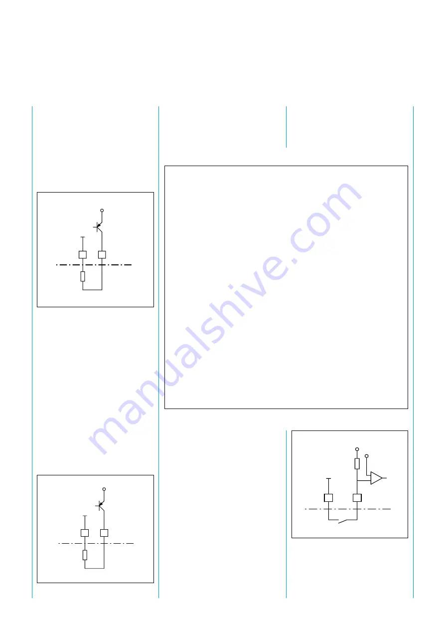
A semiconductor output provides
the exact status of the protective
zone (Fig. 16). This output has no
safety relevance.
Prot. zone free:
output live
Protective zone
interrupted:
no output
The light grid is monitored con-
tinuously for contamination. The
status is signalled by means of the
contamination semiconductor out-
put (Fig. 17).
Light grid not
contaminated:
no output
Light grid
contaminated:
output live
7
8
RL
+24V
Fig. 16. The semiconductor output gives
the actual status of the protective zone
Fig. 17. Contamination semiconductor out-
put
9
10
RL
+24V
With restart interlock
After the protective zone has been
interrupted or a test performed, the
contact of the main and auxiliary re-
lays do not close until the machine
control has been actuated. This
means that the machine cannot
resume operation until the protective
zone is clear again and the machine
control has been actuated.
If the duration of the test signal is less
than 100 ms, it is not necessary to
actuate the machine control.
The machine control must also be
actuated after the supply voltage has
been applied in this operating mode.
Without restart interlock
After the protective zone has been
interrupted or a test performed, the
contact of the main and auxiliary re-
lays close immediately after the pro-
tective zone has been cleared. It is
not necessary to actuate the machine
control. Operating modes are set via
the DIP switches on the control unit
board.
Fig. 18. The machine control is implemented
as a make contact
1
2
+24V
+4V
–
1,2 k
Ω
Control switch


