8018061/2015-04-13
• Subject to change without notice • SICK AG • Waldkirch • Germany • www.sick.com
2
Lector
®
632 | SIcK
Image handling controls
The image handling controls are used to change how
images are viewed.
Button
Function
Description
Select
Click and drag to change region
size and position.
Move
Click and drag to move the image.
Zoom
Click and drag upwards to zoom in
and downwards to zoom out.
Home
Click to fit image area to view.
Filmstrip
The expandable filmstrip area shows the image his
-
tory as thumbnails. When the image acquisition is
stopped it is possible to click a thumbnail to see it
enlarged.
information area
The expandable information area contains the
D
evice
infO
, l
Ogs
and
s
ystem
status
tabs.
The
D
evice
infO
tab displays device-related information
such as IP address and serial number.
The
l
Ogs
tab contains controls to retrieve logged
images.
The
s
ystem
status
tab shows system warnings and
errors.
Workflow
Follow the workflow in the parameter panel to config
-
ure the Lector63x. While the steps are arranged in the
typical configuration order, it is possible to navigate
freely between the steps.
1. Image
The
i
mage
workflow step controls how and when im
-
ages are acquired.
The
l
ens
& f
Ocus
section controls lens type selection
and displays focus feedback.
The
b
rightness
section controls the visual quality of
acquired images. Use the
a
utO
gain
button to automati-
cally adjust the gain.
The
i
lluminatiOn
section controls the internal and exter-
nal lighting behavior. The internal lighting is enabled
by default.
NOTICE
For Lector632x Flex, the focusing of the image is
done mechanically on the device (S-mount) or on
the lens (C-mount). To protect the device (S-mount)
from focus manipulation attach the supplied round
label to the hole in the device lid.
The
triggering
section controls the acquisition mode
and triggering method:
acquisition
mode
Description
Single image
•
Acquires one image and outputs one
result per trigger signal.
•
Used when there is only one acquisition
and analysis per object.
•
Used when the code is precisely
positioned on the object in high speed
applications.
Image series
•
Acquires a series of images and typically
outputs one combined result per trigger
signal.
•
Used when the object is larger than the
field of view and the exact code position
is unknown.
•
Used to increase read rate by acquiring
each code multiple times.
Image series is enabled by default.
2. task
The
t
ask
workflow step contains the code reading
parameters.
The
c
ODe
reaDer
settings
section determines which
code types to read. Advanced settings are available
for performance optimization.
The
c
ODe
reaDer
results
section contains unformatted
results for the current image, such as the read result
and code print quality.
The results are presented in a table where each row
represents one code.
3. results
The
r
esults
workflow step contains settings for result
timing, post-processing and formatting.
The
O
utPut
cOntrOl
section determines when the result
shall be output, either:
•
Directly when processing is ready
• At a fixed response time
The
c
Ounters
section contains counters which for
example can be used to set conditional outputs.
The
c
OnDitiOns
section allows creation of custom condi-
tions for device control and result logic. The
g
OOD
r
eaD
condition is pre-defined as an example:
The
D
igital
OutPuts
section specifies which results are
published on the available outputs.
In the
O
utPut
fOrmat
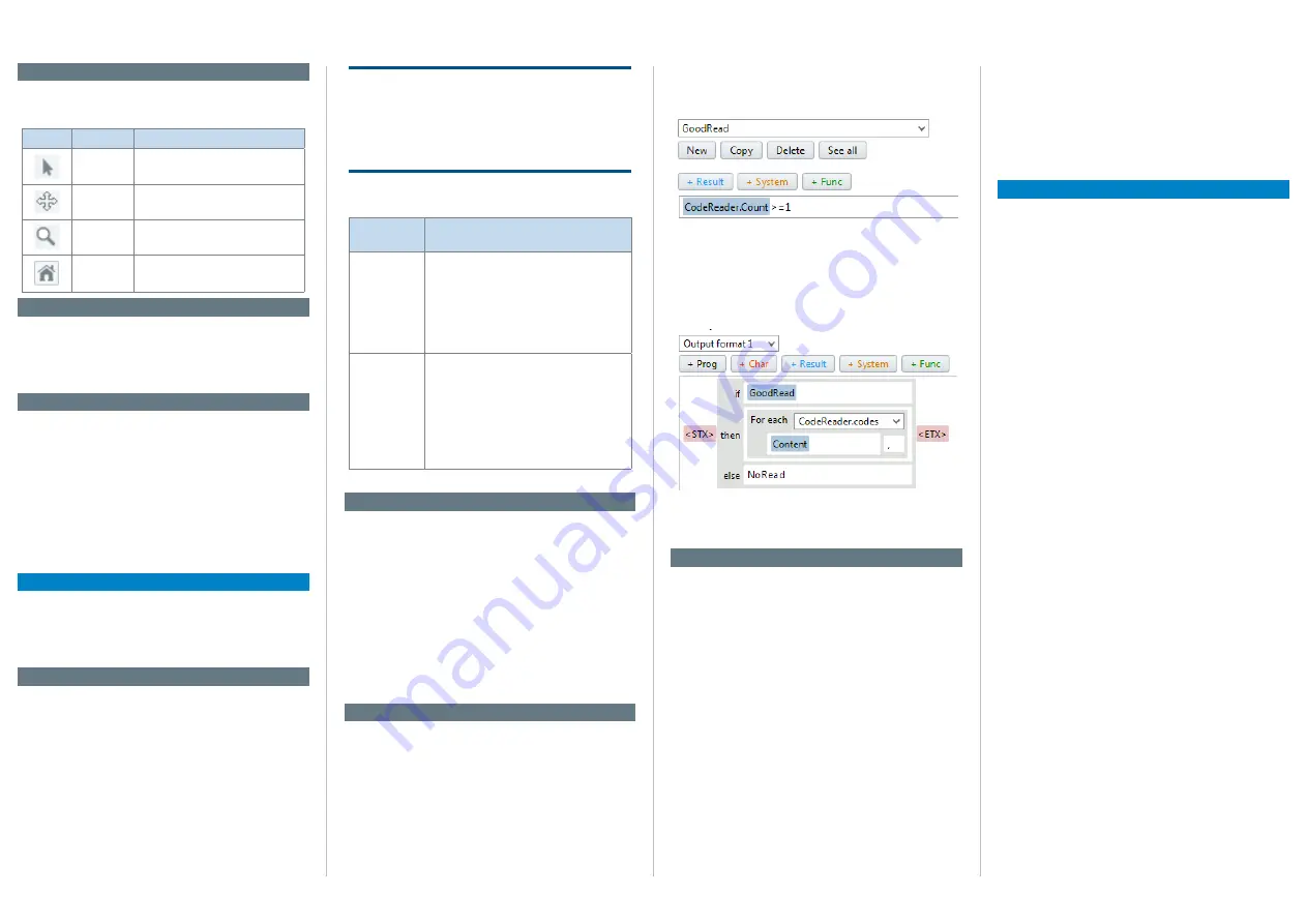
section, the decoding result
can be formatted to a string in a visual editor. The
example below shows how the GoodRead condition is
used to output the content of all read codes.
The
b
eePer
, f
unctiOn
leD
and
f
eeDback
sPOtlight
sec-
tions contain settings to define custom outputs for
monitoring results without a screen.
4. interfaces
The
i
nterfaces
workflow step contains settings for con
-
nections to external interfaces.
The
i/O
DefinitiOns
section defines the physical behav
-
ior of the digital inputs and outputs.
The
e
thernet
section sets up Ethernet communica-
tions with peripheral equipment.
The
s
erial
section sets up serial communications with
peripheral equipment.
The
l
Ogging
section controls logging of data from the
device to internal and external destinations: Device
RAM, MicroSD card and external FTP server.
The
e
ncODer
section sets up one of the digital inputs
to receive encoder signals. For example, increment-
controlled acquisition and result output make the
system independent of conveyor speed.
The
m
aster
/s
lave
section sets up camera-to-camera
communication in a SICK CAN network.
The
f
unctiOn
buttOns
On
Device
section defines the
behavior of the device buttons.
The
D
evice
time
section specifies how to set the device
time manually or to synchronize with an external time
server.
License text
SICK uses open source software in its Lector63x sen-
sors. This software is licensed by the rights holders
using the following licenses among others: the free
licenses GNU General Public License (GLP Version2,
GPL Version3) and GNU Lesser General Public
License (LGPL), the MIT license, zLib license, and the
licenses derived from the BSD license.
This Program is distributed in the hope that it will be
useful, but WITHOUT ANY WARRANTY; without even
the implied warranty for merchantability or fitness
for a particular purpose. See the GNU General Public
License for more details.
View the complete license texts here: www.sick.com/
licencetexts. A printed copy of the license texts is also
available on request.


