Operating Instructions
Chapter
5
LD-MRS
Electrical installation
8012948/ZMQ0/2017-06-09
©
SICK AG · Germany · All rights reserved · Subject to change without notice
71
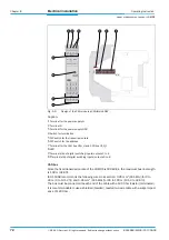
Caption:
1
LED
2
Terminal strip of the digital switching inputs/outputs
3
DIP switch for the transmission rate
4
DIP switch for the address
5
Terminal V
+PWR
6
Terminal V
PWR
7
Terminal for the power supply V+
8
Terminal for the power supply GND
9
Terminal for CAN bus CAN_L
bl
Terminal for CAN bus CAN_H
bm
Termination switch
Fig. 5-4:
Design of the CAN module
μ
CAN.8.dio-BOX
Modul ID
Baud
Term
Off/On
CAN_H
CAN_L
GND
V+
V-
P
W
R
V+P
WR
I/O_1
I/O_2
I/O_3
I/O_4
I/O_5
I/O_6
I/O_7
I/O_8
NS
MS
1
2
3
4
5 6 7 8 9
11
10


