


- 16 -
Step 6
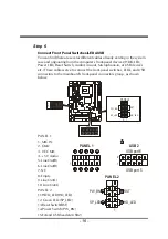
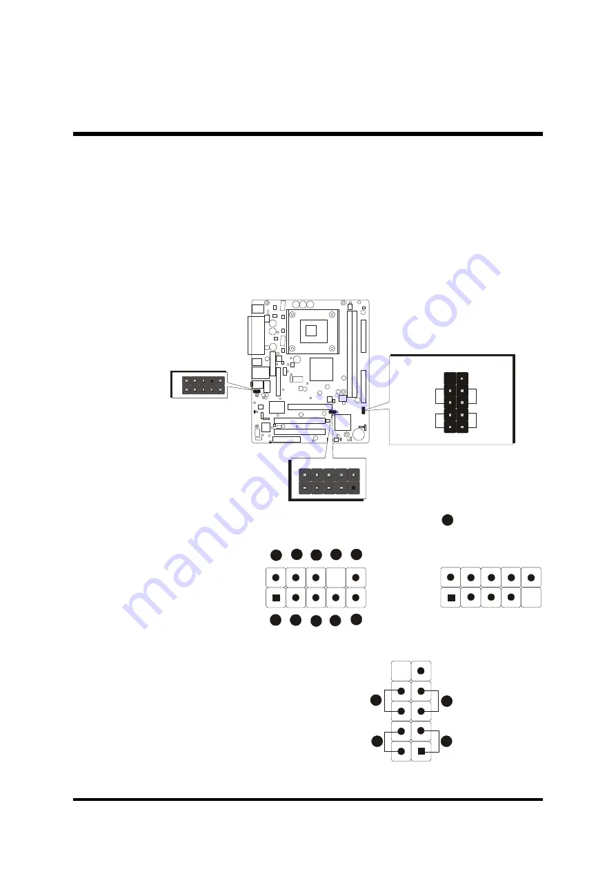
Connect Front Panel Switches/LEDs/USB
You can find there are several different cables already existing in the system
case and originating from the computer's front-panel devices (HDD LED,
Power LED, Reset Switch, Audio Line-out, Microphone-in, or USB devices
etc.) These cables serve to connect the front-panel switches, LEDs, and USB
connectors to the mainboard's front-panel connectors group , as shown
below.
PANEL 1
1. MIC IN
2. GND
3. VCC MIC
4. +5V Audio
5. Line Out(R)
6. Line Out(R)
7. NC
8. Empty
9. Line Out(L)
10. Line Out(L)
PANEL 2
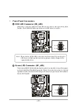
11.HDD_LED(HD_LED)
12. Green LED (SP_LED)
13.Reset Switch(RST)
14.Power Switch (PW_BN)
15.Extend USB headers(USB2)
1
2
3
4
5
6
7
8
9
10
PANEL 1
1
USB port 6
USB 2
USB port 5
15
1
2
1
HD_LED
SP_LED
RST
PW_BN
14
12
11
13
PANEL 2
1
PA
N
EL
1
1
USB2
PANEL2
1
2
SP_LED
HD_LED
PW_BN
RST


