background image

ENGLISH

ENGLISH

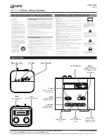
TIPS FOR ACHIEVING OPTIMUM PERFORMANCE

S

Maintain a line-of-sight between the transmitter and receiver antennas.
Avoid placing transmitter and receiver where metal or other dense materi-
als may be present.

S

Avoid placing the receiver near computers or other RF generating equip-
ment.

S

Avoid placing the receiver in the bottom of an equipment rack unless the
antennas are remotely located.

S

Use the proper receiver antennas.

S

Point the antenna tips away from each other at a 45

°

 angle from vertical,

and keep them away from large metal objects.

S

Maintain a distance of at least 10 ft between the transmitter and receiver to
prevent overloading the receiver.

S

Do not obstruct the transmitter antennas with your hands.

S

Use the proper cable when remotely locating receiver antennas. For best per-
formance, use Shure UA825 or UA850 low loss coaxial antenna cable, or 50

low loss cable such as RG8.

S

Use Shure UA830 Active Remote Antenna Kit for remote antenna placement.

S

Mount diversity antennas at least 

1

/

4

-wave apart, although spacing of 1.5 m

(60 inches) or more is preferred. This can be achieved by remote placement
of one or both antennas using Shure UA825 or UA850 low–loss coaxial
cable and a Shure UA830 Active Remote Antenna Kit. For multiple system
installations, use the Shure UA840 Antenna/Power Distribution System.

TROUBLESHOOTING

Some common problems and their solutions are identified in the table below. If you

are unable to solve a problem, contact your dealer or the Shure Service Department
at 1-800-516-2525 (7:30 am to 4:00 pm, Central Standard Time). In Europe, call
49-7131-72140; other international users call Shure in the U.S.A. at  847-866-2200.
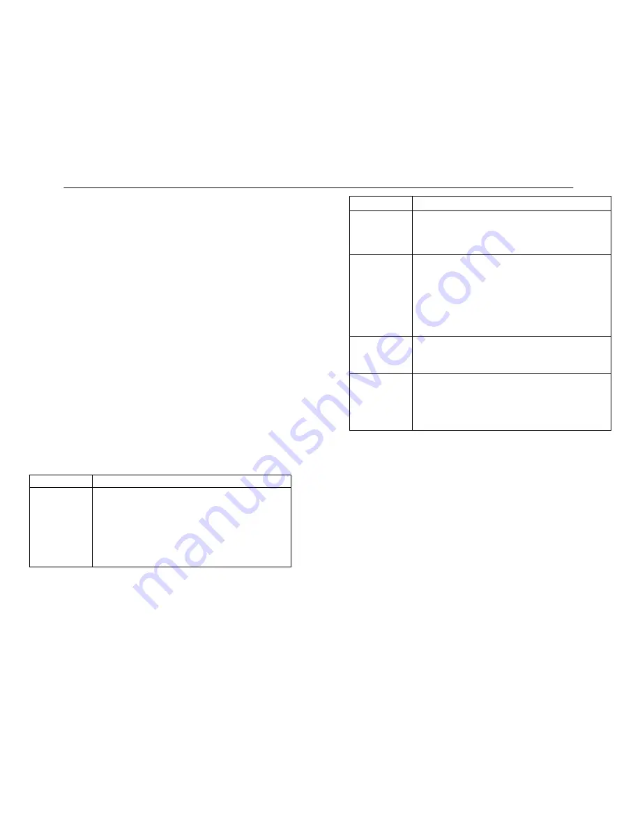
Problem

Solution

No sound; receiver
RF light(s) and
AUDIO LEDs not
glowing.

Make sure Power switches on transmitter and receiver are on.
Check transmitter Power/Battery Fuel Gauge. Replace battery if
necessary.
Make sure transmitter and receiver frequency Group/Channel set-
tings are identical.
Check receiver squelch setting.
Check receiver antenna connection(s).
Make sure at least one antenna is in the line of sight of the transmit-
ter. If necessary, reduce the distance between transmitter and re-
ceiver.

Problem

Solution

No receiver sound;
RF and Audio Level
meter LEDs glow-
ing.

Turn up the receiver audio output Level control.
Check for proper connection between receiver and microphone
mixer.
Talk into the microphone and observe the receiver audio level
LEDs. If they glow, the problem is elsewhere in the sound system.

Received signal is
noisy or contains
extraneous sounds
with transmitter on.

Check transmitter Power/Battery Fuel Gauge and replace battery
if power is low.
Remove local sources of RF interference, such as lighting equipment.
If using a guitar or other instrument, make sure it is connected to
the U1 with a Shure WA302 adapter cable.
Two transmitters may be operating on the same frequency. Locate
and turn one off or change frequency.
Signal may be too weak. Reposition antennas closer to the trans-
mitter.
Adjust receiver squelch control.

Noise from receiv-
er with transmitter
off.

Adjust receiver squelch control.
Remove local sources of RF interference, such as lighting equipment.
Try using another frequency.
Reposition the receiver or antennas.

Momentary loss of
sound as transmit-
ter is moved
around performing
area.

Reposition receiver and perform another “walkthrough” test and
observe the RF level or Diversity signal indicators. If audio drop-
outs persist, mark these “dead spots” in the performing area and
avoid them during the performance.
Decrease squelch control setting, even though noise in “dead
spots” may increase slightly.
Move antennas to a remote location (use UA830 kit)

SPECIFICATIONS

Refer to the supplement that came with your system.

LICENSING INFORMATION

Changes or modifications not expressly approved by Shure Brothers Inc. could void

your authority to operate the equipment. Licensing of Shure wireless microphone equip-

ment is the user’s responsibility, and licensability depends on the user’s classification

and application, and on the selected frequency. Shure strongly urges the user to contact

the appropriate telecommunications authority concerning proper licensing, and before

choosing and ordering frequencies other than standard frequencies.

32

33

Summary of Contents for U Series

Page 1: ...ed The Sound of Professionals Worldwide Shure Brothers Incorporated 222 Hartrey Avenue Evanston Illinois 60202 3696 Phone 847 866 2200 Fax 847 866 2279 In Europe Phone 49 7131 72140 Fax 49 7131 721414 Internationally Phone 847 866 2200 Fax 847 866 2585 UHF User s Guide ...

Page 2: ...cking the Receiver Display 20 Unlocking the Receiver Display 20 TRANSMITTER SETUP 21 Transmitter Battery Installation 21 Checking TransmitterBatteries 22 Connecting a Lavalier Microphone or Instrument Cable to the U1 Transmitter 23 PROGRAMMING THE TRANSMITTER 23 ChangingTransmitterGroup ChannelSettings 23 Locking the Power Switch in the ON Position 26 Cancelling the Power On Lock Function 26 Activ...

Page 3: ...hrough your receiver Dual RF Level Meters The U4S and U4D receivers have two RF meters one for each antenna The dual meters indicate received signal strength at each antenna and make it easier to identify and troubleshoot dead spots Audio Metering Each receiver includes a seven segment audio meter that lets you monitor audio level and helps optimize transmitter gain setting TransmitterDisplay Show...

Page 4: ...nd off 5 On Off LED Glows green when the U1 is turned on 6 Belt Clip Allows the transmitter to be easily worn on a belt waistband or guitar strap 7 MODE Button Selects the parameter Group or Channel you wish to change 8 SET Button Changes transmitter Group and Channel settings Also used with the MODE button to lock power on and to lock the frequency and channel setting 9 Audio Gain Control Allows ...

Page 5: ...l keys 5 ON OFF Switch Turns transmitter power on and off 6 Antenna Helical antenna is attached to the end of the U2 transmitter The anten na can be replaced in the field by a qualified technician 7 Battery Compartment Contains two 1 5 V AA batteries Duracell MN1500 rec ommended 8 MODE Button Selects the parameter Group or Channel you wish to change 9 SET Button Changes transmitter Group and Chann...

Page 6: ...tor on or off If you are using a Model U4D Receiver press the Headphone Volume Control knob once to select Receiver 1 or twice to select Receiver 2 depending on which section you wish to monitor 10 Headphone Monitor Status These LEDs glow yellow when the headphone monitor circuit is turned on or off NOTE The Tone Key feature is present only on the receiver output As a result you may hear an occasi...

Page 7: ... ADAPTER BULKHEAD ADAPTER 2 Connect the supplied antenna cables to the receiver and the bulkhead adapters as shown in Figure 7 RECEIVER TOP VIEW FIGURE 7 ANTENNA CABLE ANTENNA CABLE NOTE Shure recommends connecting the bulkhead adapter and antenna cables before mounting the receiver in a rack Once the receiver is in the rack it is more diffi cult to insert the bulkhead adapters and connect the ant...

Page 8: ...with a UA830 Active Remote Antenna Kit VIEWING CURRENT RECEIVER SETTINGS To view current settings on the receiver display proceed as follows 1 Turn the receiver on by pressing upper half of the POWER switch 2 Press either the button or the button on the receiver front panel to scroll through the current settings PROGRAMMING THE RECEIVER You can change the receiver Group Channel setting the operati...

Page 9: ...to the original setting See Figure 15 FIGURE 15 NOTE If more than 20 seconds of inactivity elapse the display will return to the original settings Changing Receiver Frequency Setting 1 Press the MENU button The MENU display will appear as shown in Figure 16 FIGURE 16 2 Press either the or button to reach the SET FREQ display shown in Figure 17 FIGURE 17 3 Press the SELECT button The current operat...

Page 10: ...ue until you have spelled out the entire name 6 When the new name has been completely entered press the MENU button SAVE will appear followed by YES NO Press the button to save the new name and return to the Group Channel TV display Press the button to make more changes See Figure 24 FIGURE 24 NOTE If more than 20 seconds of inactivity elapse the display will return to the original settings Changi...

Page 11: ...5 5 97 8 6 0 98 1 6 5 98 4 7 0 98 7 7 5 99 0 8 0 99 3 8 5 99 6 9 0 99 9 9 5 100 2 Minimum 10 Open U4S and U4D squelch values differ slightly Specifications subject to change without notice 5 Once you have reached the desired squelch level press the MENU button SAVE will appear followed by YES NO as shown in Figure 28 Press the button to make more changes or press to save the new squelch setting an...

Page 12: ...eventing the user from changing any settings TRANSMITTER SETUP Transmitter Battery Installation Figure 34 1 Make sure the transmitter power ON OFF switch is in the OFF position 2 Open the transmitter battery compartment as follows U1 Transmitter Squeeze the two tabs on either side of the transmitter and flip the battery cover down U2 Transmitter Unscrew the battery cover and slide it down FIGURE 3...

Page 13: ...wn the microprocessor will turn off RF power the Tone key and the display Connecting a Lavalier Microphone or Instrument Cable to the U1 Transmitter Figure 36 1 Plug the microphone cable or instrument cable into the transmitter input connector 2 Attachthelavaliermicrophonetoyourtie shirtorcollar Ifyouareusingaheadset put the headset on 3 If an instrument adapter cable is used attach the other end ...

Page 14: ...t increment mode if more than 20 seconds of inactivity elapse the display will return to the original settings 5 Press the MODE button again so that only the Channel number is displayed as shown in Figure 40 FIGURE 40 6 Press the SET button to change the Channel setting as shown in Figure 41 FIGURE 41 7 Press the MODE button again so that the new Group and Channel numbers are both displayed NOTE O...

Page 15: ...e Transmit ter Power On Lock function can also be cacelled by removing the batteries FIGURE 43 Activating the Frequency Lock Function The Frequency Lock function prevents accidental frequency changes and is par ticularly useful in preventing accidental or unauthorized changes The lock function is retained in memory even if the transmitter is turned off and the batteries removed To activate the Fre...

Page 16: ...ushing this knob selects the receiver section you wish to monitor 8 Begin speaking or playing your instrument Rotate the OUTPUT LEVEL knob as necessary to achieve desired receiver output levels NOTE If the red PEAK LEDs on the receiver do not flicker during the loudest sounds or if they are always on the transmitter gain may need to be increased or decreased Refer to Adjusting the Transmitter Audi...

Page 17: ...OTE The factory preset 6 dB should match most applications Before chang ing the audio input level try adjusting the transmitter gain see Figure 47 The U1 body pack transmitter has an attenuator switch that allows you to set the au dio input level for different types of applications Use one of the following three set tings according to the type of input source you are using 0 dB fully counterclockw...

Page 18: ...a connection s Makesureatleastoneantennaisinthelineofsightofthetransmit ter If necessary reduce the distance between transmitter and re ceiver Problem Solution No receiver sound RFandAudioLevel meter LEDs glow ing Turn up the receiver audio output Level control Check for proper connection between receiver and microphone mixer Talk into the microphone and observe the receiver audio level LEDs If th...

Page 19: ... 6 Diversity A Analog Output 2 kΩ 1 4 V 7 Network In terrupt Digital Input Not Applicable 1 4 V 8 Network In terrupt Digital Output Busy Not Applicable 1 4 V 9 Serial Data Output Digital Output Not Applicable 1 4 V 10 Serial Data Input Digital Input Not Applicable 1 4 V 11 5V Not Applicable 5 V 12 5V Not Applicable 5 V 13 5V indicates unit is dual channel Not Applicable 1 4 V 14 Audio Meter Analog...

Reviews: