background image

ENGLISH

ENGLISH

NOTE: When the Frequency Lock function is engaged, the Power On Lock func-
tion can still be activated. However, if the Power Lock and the Frequency Lock
functions are engaged, the Power Lock function must be disengaged before the
Frequency Lock can be cancelled.

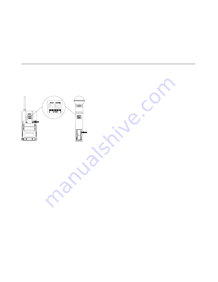
Cancelling the Frequency Lock Function (Figure 46)

To cancel the Frequency Change Lock function, repeat the steps in the preceding

Activating the Frequency Lock Functio

paragraph. When the frequency lock func-

tion is turned off, Fr UL will appear on the transmitter display, as shown in Figure 46.

FIGURE 46


OPERATING THE U1 BODY–PACK SYSTEM

1. Clip the U1 body pack transmitter to your belt, waistband, or guitar strap. Push the

body pack all the way down.

2. Connect the lavalier microphone, headset microphone, or instrument adapter cable

to the U1 transmitter.

3. If you will be using a lavalier microphone, clip it to your tie, lapel, or other garment.

If you are using a headset, put the headset on. If you are using an instrument
adapter cable, plug it into the instrument.

4. Slide the transmitter power ON/OFF switch to the ON position. The green power

on LED will glow and the Group and Channel number will appear on the transmit-
ter display, along with a bar graph that indicates battery power level.

5. Turn the receiver on by pressing the upper section of the POWER switch. The re-

ceiver display and RF LEDs will glow.

6. Make sure the transmitter and receiver are tuned to the same Group, Channel, and

Frequency. If necessary, change the settings on either the transmitter or receiver.

7. If using a headphone monitor, push the monitor knob on the receiver (U4S) or half

the way down (U4D). The headphone monitor light, located below the knob, will
glow. Rotate the knob until the headphone volume is at a comfortable level.

NOTE: If you are using the U4D receiver, pushing this knob selects the receiver
section you wish to monitor.

8. Begin speaking or playing your instrument. Rotate the OUTPUT LEVEL knob as

necessary to achieve desired receiver output levels.

NOTE: If the red PEAK LEDs on the receiver do not flicker during the loudest
sounds, or  if they are always on, the transmitter gain may need to be increased or
decreased. Refer to Adjusting the Transmitter Audio Gain Level. If the system still
does not operate properly, consult the Troubleshooting table.

9.

When the performance or presentation is over, slide the transmitter ON/OFF
switch to the OFF position to conserve battery power.

OPERATING THE U2 HAND-HELD SYSTEM

1. Slide the transmitter power ON/OFF switch to the ON position. The Group and

Channel number will appear on the transmitter display, along with a bar graph indi-
cating battery power level.

2. Turn the receiver on by pressing the upper section of the POWER switch. The re-

ceiver display and the RF lights will glow.

3. Make sure the transmitter and receiver are tuned to the same Group, Channel,

and Frequency. If necessary, change the settings on the transmitter or receiver.

4. If using a headphone monitor, push the monitor knob on the receiver to turn the

monitor circuit on. The ON LED, located below the knob, will glow. Rotate the knob
until the headphone volume is at a comfortable level.

NOTE: If you are using the U4D receiver, pushing this knob selects the receiver
section you wish to monitor.

5. Begin speaking or singing into the microphone. Rotate the OUTPUT LEVEL knob

as necessary to increase or decrease receiver output levels.

NOTE: If the red PEAK LEDs on the receiver do not flicker during the loudest
sounds, or if they are always on, the transmitter gain may need to be increased or
decreased. Refer to Adjusting the Transmitter Audio Gain Level. If the system still
does not operate properly, consult the Troubleshooting table.

6. When the performance or presentation is over, slide the transmitter power ON/

OFF switch to the OFF position to conserve battery power.

28

29

Summary of Contents for U Series

Page 1: ...ed The Sound of Professionals Worldwide Shure Brothers Incorporated 222 Hartrey Avenue Evanston Illinois 60202 3696 Phone 847 866 2200 Fax 847 866 2279 In Europe Phone 49 7131 72140 Fax 49 7131 721414 Internationally Phone 847 866 2200 Fax 847 866 2585 UHF User s Guide ...

Page 2: ...cking the Receiver Display 20 Unlocking the Receiver Display 20 TRANSMITTER SETUP 21 Transmitter Battery Installation 21 Checking TransmitterBatteries 22 Connecting a Lavalier Microphone or Instrument Cable to the U1 Transmitter 23 PROGRAMMING THE TRANSMITTER 23 ChangingTransmitterGroup ChannelSettings 23 Locking the Power Switch in the ON Position 26 Cancelling the Power On Lock Function 26 Activ...

Page 3: ...hrough your receiver Dual RF Level Meters The U4S and U4D receivers have two RF meters one for each antenna The dual meters indicate received signal strength at each antenna and make it easier to identify and troubleshoot dead spots Audio Metering Each receiver includes a seven segment audio meter that lets you monitor audio level and helps optimize transmitter gain setting TransmitterDisplay Show...

Page 4: ...nd off 5 On Off LED Glows green when the U1 is turned on 6 Belt Clip Allows the transmitter to be easily worn on a belt waistband or guitar strap 7 MODE Button Selects the parameter Group or Channel you wish to change 8 SET Button Changes transmitter Group and Channel settings Also used with the MODE button to lock power on and to lock the frequency and channel setting 9 Audio Gain Control Allows ...

Page 5: ...l keys 5 ON OFF Switch Turns transmitter power on and off 6 Antenna Helical antenna is attached to the end of the U2 transmitter The anten na can be replaced in the field by a qualified technician 7 Battery Compartment Contains two 1 5 V AA batteries Duracell MN1500 rec ommended 8 MODE Button Selects the parameter Group or Channel you wish to change 9 SET Button Changes transmitter Group and Chann...

Page 6: ...tor on or off If you are using a Model U4D Receiver press the Headphone Volume Control knob once to select Receiver 1 or twice to select Receiver 2 depending on which section you wish to monitor 10 Headphone Monitor Status These LEDs glow yellow when the headphone monitor circuit is turned on or off NOTE The Tone Key feature is present only on the receiver output As a result you may hear an occasi...

Page 7: ... ADAPTER BULKHEAD ADAPTER 2 Connect the supplied antenna cables to the receiver and the bulkhead adapters as shown in Figure 7 RECEIVER TOP VIEW FIGURE 7 ANTENNA CABLE ANTENNA CABLE NOTE Shure recommends connecting the bulkhead adapter and antenna cables before mounting the receiver in a rack Once the receiver is in the rack it is more diffi cult to insert the bulkhead adapters and connect the ant...

Page 8: ...with a UA830 Active Remote Antenna Kit VIEWING CURRENT RECEIVER SETTINGS To view current settings on the receiver display proceed as follows 1 Turn the receiver on by pressing upper half of the POWER switch 2 Press either the button or the button on the receiver front panel to scroll through the current settings PROGRAMMING THE RECEIVER You can change the receiver Group Channel setting the operati...

Page 9: ...to the original setting See Figure 15 FIGURE 15 NOTE If more than 20 seconds of inactivity elapse the display will return to the original settings Changing Receiver Frequency Setting 1 Press the MENU button The MENU display will appear as shown in Figure 16 FIGURE 16 2 Press either the or button to reach the SET FREQ display shown in Figure 17 FIGURE 17 3 Press the SELECT button The current operat...

Page 10: ...ue until you have spelled out the entire name 6 When the new name has been completely entered press the MENU button SAVE will appear followed by YES NO Press the button to save the new name and return to the Group Channel TV display Press the button to make more changes See Figure 24 FIGURE 24 NOTE If more than 20 seconds of inactivity elapse the display will return to the original settings Changi...

Page 11: ...5 5 97 8 6 0 98 1 6 5 98 4 7 0 98 7 7 5 99 0 8 0 99 3 8 5 99 6 9 0 99 9 9 5 100 2 Minimum 10 Open U4S and U4D squelch values differ slightly Specifications subject to change without notice 5 Once you have reached the desired squelch level press the MENU button SAVE will appear followed by YES NO as shown in Figure 28 Press the button to make more changes or press to save the new squelch setting an...

Page 12: ...eventing the user from changing any settings TRANSMITTER SETUP Transmitter Battery Installation Figure 34 1 Make sure the transmitter power ON OFF switch is in the OFF position 2 Open the transmitter battery compartment as follows U1 Transmitter Squeeze the two tabs on either side of the transmitter and flip the battery cover down U2 Transmitter Unscrew the battery cover and slide it down FIGURE 3...

Page 13: ...wn the microprocessor will turn off RF power the Tone key and the display Connecting a Lavalier Microphone or Instrument Cable to the U1 Transmitter Figure 36 1 Plug the microphone cable or instrument cable into the transmitter input connector 2 Attachthelavaliermicrophonetoyourtie shirtorcollar Ifyouareusingaheadset put the headset on 3 If an instrument adapter cable is used attach the other end ...

Page 14: ...t increment mode if more than 20 seconds of inactivity elapse the display will return to the original settings 5 Press the MODE button again so that only the Channel number is displayed as shown in Figure 40 FIGURE 40 6 Press the SET button to change the Channel setting as shown in Figure 41 FIGURE 41 7 Press the MODE button again so that the new Group and Channel numbers are both displayed NOTE O...

Page 15: ...e Transmit ter Power On Lock function can also be cacelled by removing the batteries FIGURE 43 Activating the Frequency Lock Function The Frequency Lock function prevents accidental frequency changes and is par ticularly useful in preventing accidental or unauthorized changes The lock function is retained in memory even if the transmitter is turned off and the batteries removed To activate the Fre...

Page 16: ...ushing this knob selects the receiver section you wish to monitor 8 Begin speaking or playing your instrument Rotate the OUTPUT LEVEL knob as necessary to achieve desired receiver output levels NOTE If the red PEAK LEDs on the receiver do not flicker during the loudest sounds or if they are always on the transmitter gain may need to be increased or decreased Refer to Adjusting the Transmitter Audi...

Page 17: ...OTE The factory preset 6 dB should match most applications Before chang ing the audio input level try adjusting the transmitter gain see Figure 47 The U1 body pack transmitter has an attenuator switch that allows you to set the au dio input level for different types of applications Use one of the following three set tings according to the type of input source you are using 0 dB fully counterclockw...

Page 18: ...a connection s Makesureatleastoneantennaisinthelineofsightofthetransmit ter If necessary reduce the distance between transmitter and re ceiver Problem Solution No receiver sound RFandAudioLevel meter LEDs glow ing Turn up the receiver audio output Level control Check for proper connection between receiver and microphone mixer Talk into the microphone and observe the receiver audio level LEDs If th...

Page 19: ... 6 Diversity A Analog Output 2 kΩ 1 4 V 7 Network In terrupt Digital Input Not Applicable 1 4 V 8 Network In terrupt Digital Output Busy Not Applicable 1 4 V 9 Serial Data Output Digital Output Not Applicable 1 4 V 10 Serial Data Input Digital Input Not Applicable 1 4 V 11 5V Not Applicable 5 V 12 5V Not Applicable 5 V 13 5V indicates unit is dual channel Not Applicable 1 4 V 14 Audio Meter Analog...

Reviews: