background image

17

English  –

PARAMETRIC EQUALIZER

The DP11EQ also contains two parametric equalizers, with up to 11 parametric filters possible.

These equalizers can be used for tuning out feedback or other anomalies in the frequency response
of the acoustics of a room or sound system.  There are high- and low-frequency rolloff/shelf filters,
and parametric filters with adjustable frequency, gain, and width.  Parametric filters are represented
as dots, while the high- and low-frequency filters are represented as squares.  When a filter is
selected, the dot representing that filter changes color to indicate that it has been selected.
Parametric filters can be edited using cut, copy, and paste.

Note on processing resources:  The number of filters available is directly affected by the

amount of dynamics processing.  The AGC leveler takes the space of 7 parametric filters, while the no
overshoot peak limiter takes the space of 2 parametric filters.  So, if all dynamics processes are on
except leveler and peak limiter, then 9 parametric filters are available.  If the peak limiter is on with no
leveler, there are 7 parametric filters available.  If the leveler is on with no peak limiter, there are 4
parametric filters available.  If both the leveler and  peak limiter are on, there will be 2 parametric filters
available.  The number of filters also depends on whether or not both equalizers are used.  For
instance, 9 parametric filters are available if all dynamics processes are on except leveler and peak
limiter, but using only one equalizer.  If both equalizers are used in this situation, then there will be 7
parametric filters available between both equalizers.
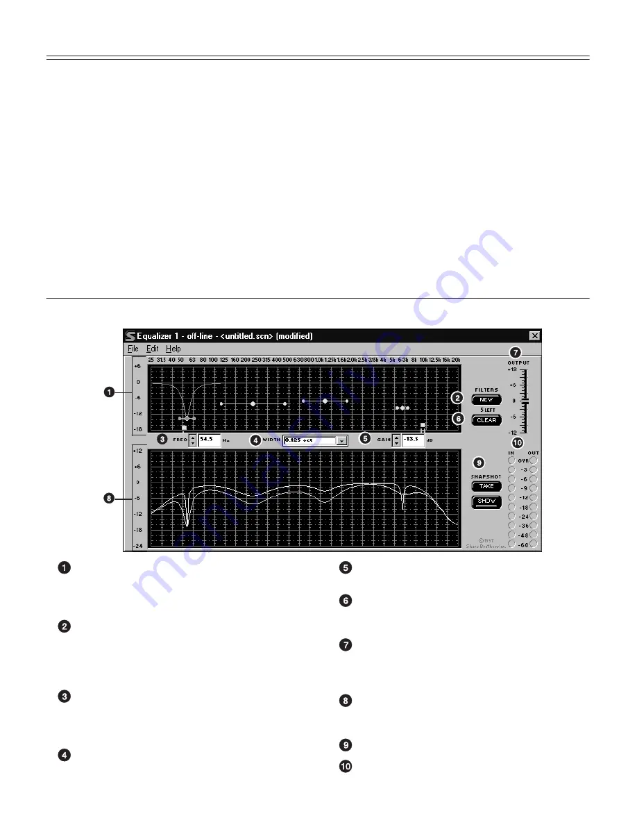
Overview

Parametric Equalizer Graph.  This graph
displays squares and dots representing the
parametric and high/low frequency filters.  Using
this graph, you can adjust all of the filters.

NEW Button.   Click on this button to create new
shelf/cut or parametric filters.  A new parametric
filter always appears at 1.0 kHz, 0dB, 2/3-octave
in width.  The number of remaining filters is
displayed underneath the button.

FREQ. Box.  This box displays the frequency
center of the currently selected filter.  Click on the
arrow buttons or type in the field to edit the
frequency.

SLOPE/WIDTH Box.  This box displays the width
of a selected parametric filter, or the slope of a
selected shelf or cut filter.

GAIN Box.  This box displays the boost or cut of
the currently selected filter.

CLEAR Button.  Click on this button to reset the
currently selected parametric filter, all filters, or an
entire equalizer.

OUTPUT Level Control.  Drag this slider to adjust
the overall gain of the equalizer section.  This can
be used in conjunction with the IN/OUT Level
Meters.

Response Curve Graph.  This graph displays the
frequency response of the equalizer.  See
Response Curve Graph.

SNAPSHOT Buttons.  See 

Snapshots.

IN and OUT Level Meters.  See 

IN/OUT Meters

and OUTPUT Control.

Summary of Contents for DP11EQ

Page 1: ...Model DP11EQ User s Guide 27A8630 Rev 2 E2006 Shure Incorporated DP11EQ Dynamics Processor Equalizer and Delay with Windows Software...

Page 2: ...English 17 DELAY English 21 SHURE LINK NETWORKS English 23 MAINTENANCE English 24 Scenes English 24 Settings English 25 Customizing Graph Colors English 25 Printing DP11EQ Settings English 26 Locking...

Page 3: ...Can be used with balanced or unbalanced outputs S No internal batteries Settings and DSP program stored in internal EEPROM S 4 dBu 10 dBV DIP switch selectable input and output levels S 80 MHz Motorol...

Page 4: ...is powered on Back Panel Power Connector with Integral Fuse Connects to AC power The fuse is located in the drawer below the connector 9 Pin RS 232 Port Connects the unit to a computer For use with D...

Page 5: ...gned a unique Device ID 0 through 15 DIP switches 1 through 4 on the rear panel are used to set the Device ID To change the Device ID align the switches according to the illustrations below The unit c...

Page 6: ...e Appendix C for descriptions of cable and connection information Main Amplifier The DP11EQ is most commonly placed between the main output of a mixer and the input of a power amplifier At the main ou...

Page 7: ...e insert to process the signal for that microphone only This is a common location for an leveler LINE OUT LINE IN LINE OUT LINE OUT MAIN CHANNEL 1 IN CHANNEL 1 INSERT DP11EQ LINE IN MIXER POWER AMPLIF...

Page 8: ...Use the proper cable purchased separately For RS 232 cable diagrams see Appendix C Cables and Connectors TO DP11EQ RS 232 CABLE 9 PIN MALE TO COMPUTER RS 232 CONNECTOR 1 Connect the 9 pin plug male o...

Page 9: ...ick on the COM port option of the drop down menu 4 In the Serial Port Options window select an available COM port on the computer 5 Click on the OK button NOTE The COM port selection is saved in the D...

Page 10: ...ou to adjust parameters Near the top there is a Dynamic Gain meter corresponding to the one on the front panel of the DP11EQ There are also Snapshot buttons for storing and viewing an original respons...

Page 11: ...s meter displays the net gain of the unit CONNECT Button and LED This button brings the DP11EQ plugged into the computer online along with any other devices networked via Shure Link When connected the...

Page 12: ...n this meter to activate Dynamics Transfer Curve Graph This displays the effect of all dynamics processing on the input signal Dynamic Input Output Meter Embedded in the graph is a meter which display...

Page 13: ...a gain change to take full effect once a threshold has been crossed To adjust the attack click on the and buttons of the ATTACK box or type the desired value in the edit box RATIO The Ratio determines...

Page 14: ...eases below the threshold GATE HOLD The gate hold determines the amount of time the DP11EQ sustains the gate after the levels have fallen below the threshold The gate hold is a time duration that come...

Page 15: ...y the ratio or the maximum gain line maximum gain 12 dB To prevent the possibility of gain increase in a feedback prone system the AGC should be used with the threshold and hinge at the same settings...

Page 16: ...ess of the slope of the ratio setting The hard knee works aggressively applying the compression slope immediately once the signal rises above the threshold The soft knee gradually applies compression...

Page 17: ...ect equipment from the loudest dynamic bursts which could potentially damage equipment the attack is always instant the ratio always infinite and the decay fast so Threshold is the only parameter nece...

Page 18: ...ther or not both equalizers are used For instance 9 parametric filters are available if all dynamics processes are on except leveler and peak limiter but using only one equalizer If both equalizers ar...

Page 19: ...to the selected filter Clicking on the and buttons will adjust the gain of the filter With the high and low shelving filters the response will shelve at the level of the gain setting However once the...

Page 20: ...ere have been no changes to the curve since the snapshot was originally taken it might appear as though no snapshot has been taken This happens because the snapshot and the current curve are exactly t...

Page 21: ...click and drag the OUTPUT slider Click on the IN OUT level meters to activate or 1 Click on Options in the main menu bar of the Main Control Panel 2 Click on Meters 3 Click on Display Level Meters opt...

Page 22: ...the proper amount of delay The DP11EQ with Delay will hold that audio signal in memory releasing it to the fill loudspeaker only when it is in time with the sound from the main loudspeaker so the sou...

Page 23: ...lower the distance 5 Measure the air temperature 6 Under the Air temperature field click on the Celsius or Fahrenheit dot to select the desired type 7 In the Air temperature box click on the and butt...

Page 24: ...the computer NOTE Although a standard MIDI cable can be used to link units Shure Link is not MIDI compatible Shure Link Options Shure Link Device Menu The Device menu displays the following informati...

Page 25: ...ombination of settings these settings can be stored on disk as a Scene Although the DP11EQ automatically saves the current scene in internal memory other scenes can be saved to disk Scenes are useful...

Page 26: ...disk and recall them to another DP11EQ To recall settings 1 Click on File in the menu bar of the current panel 2 Select Recall Settings 3 On the Settings window select the desired settings name 4 Clic...

Page 27: ...20 bit resolution Voltage Gain 1 dB 1dB power off 12 dB 2 dB input 10 dBV output 4 dBu 12 dB 2 dB input 4 dBu output 10 dBv 0 dB 2 dB equal input and output sensitivities Impedance Input 47 k 20 actu...

Page 28: ...ized under Verification provision of FCC Part 15 as a Class B Digital Device DP11EQ E Conforms to European Union Directives eligible to bear CE marking Meets European Union Low Voltage Requirements VD...

Page 29: ...ith the 8 supplied screws Dual Mounted Units DATA DATA 1 Align two units side by side so that the front panels both face the same direction 2 Place the supplied straddle bars in the recesses on the to...

Page 30: ...Output Level 4 dBu 4 output level 10 dBV 10 output level 4 dBu 4 output level 10 dBV 10 output level Maximum Output Level 18 dBu 4 output level 6 dBV 10 output level 18 dBu 4 output level 6 dBV 10 ou...

Page 31: ...r Sub Return S Mixer Send to DP11EQ Input S Mixer Sub Send to DP11EQ Input SLEEVE TIP SLEEVE TIP 1 4 in Balanced to 1 4 in Unbalanced TYPICAL APPLICATIONS S Mixer Line Out to DP11EQ Input S DP11EQ Out...

Page 32: ...TIONS S Mixer Line Out to DP11EQ Input S DP11EQ Output to Amplifier Input S DP11EQ Output to Mixer Sub Return S Mixer Send to DP11EQ Input S Mixer Sub Send to DP11EQ Input PIN 1 PIN 2 PIN 3 SLEEVE TIP...

Page 33: ...ble FUNCTION RX TX DTR GND DSR RTS CTS 9 PIN CONNECTOR PIN 1 2 3 4 5 6 7 8 9 25 PIN CONNECTOR PIN 8 3 2 20 7 6 4 5 22 9 8 7 6 5 4 3 2 1 9 8 7 6 5 4 3 2 1 5 4 3 2 1 25 PIN FEMALE TO COMPUTER 9 PIN MALE...

Page 34: ...HT controls from right to left PRESS a selected button SAVE a scene RECALL a scene PRINT the settings of the current unit EXIT the program FINE ADJUST a parameter COARSE ADJUST a filter or slider UNDO...

Page 35: ...a selected parametric filter CREATE a new parametric filter FINE ADJUST the FREQUENCY of a parametric filter COARSE ADJUST the FREQUENCY of a parametric filter FINE ADJUST the GAIN of a parametric fil...

Page 36: ...Caribbean 5800 W Touhy Avenue Niles IL 60714 4608 U S A Phone 847 600 2000 U S Fax 847 600 1212 Int l Fax 847 600 6446 Europe Middle East Africa Shure Europe GmbH Phone 49 7131 72140 Fax 49 7131 7214...

Reviews: