Shure DP11EQ, User Manual
The Shure DP11EQ is a high-quality equalizer designed for professional audio applications. Enhance your sound with precision control over frequencies. For detailed instructions on how to maximize its potential, download the free User Manual from manualshive.com. Unlock the full potential of your audio equipment with this essential manual.
Share
Download


Reviews:
No comments
Related manuals for DP11EQ
2230
Brand: Tapco Pages: 12
V14
Brand: JDK Audio Pages: 8

P500
Brand: Xtant Pages: 2
P500
Brand: Xtant Pages: 9
iEQ-15
Brand: dbx Pages: 16
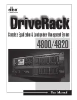
DriveRack 4800
Brand: dbx Pages: 96

EQ-1000
Brand: X4-TECH Pages: 5
MPE series
Brand: Rane Pages: 34
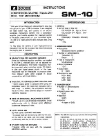
SM-10
Brand: Icom Pages: 2
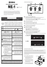
NE-1
Brand: Yamaha Pages: 2
32-2059
Brand: Radio Shack Pages: 2
ME 15S
Brand: Rane Pages: 12
GE 130
Brand: Rane Pages: 4
S-Curve 131
Brand: Samson Pages: 2

E30I
Brand: Samson Pages: 48
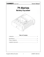
VANN-Guard 71 Series
Brand: Vanner Pages: 11
DN300
Brand: Klark Teknik Pages: 26
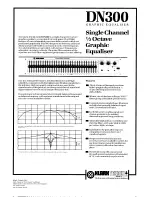
DN300
Brand: Klark Teknik Pages: 2


