Shur-Co SHUR COVER Owner'S Manual Download Page 2

Shur-Co

®

, LLC Terms & Conditions
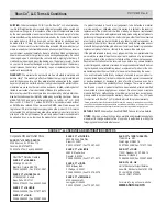
SHIPPING.

 Orders are shipped F.O.B. from the Shur-Co

®

, LLC sites listed be-

low. No full freight isallowed or prepaid shipment accepted unless quoted and 

approved in writing prior to acceptance of the order. All shipments are made 

by the most reasonable means in accordance with size and weight of order, 

unless specifi ed routing instructions are furnished by the customer. Shipments 

are made daily via U.P.S. and common carrier. Claims for shortages must 

be made within 10 days. All claims for damages or loss in transit must be 

made with the carrier. No collect calls will be accepted. To ensure delivery of 

orders, we need your full street address and phone number. When you receive 

your shipment, examine it carefully. Be sure all cartons listed on the delivery 

sheet are accounted for. Large items may be packaged separately. If a carton 

is damaged, open it and inspect the contents before signing for delivery. If 

merchandise is damaged, describe damage on the delivery receipt. Failure 

on your part to document damaged or missing merchandise on the delivery 

receipt releases the carrier of all liability; repair or replacement will be the 

customer’s responsibility.


WARRANTY.

 We warrant all new products are free of defects in materials and 

workmanship.* This warranty is effective if products are properly installed and 

used for the purpose for which they were intended and applies to the original 

buyer only. Except as set forth above or in any product-specifi c warranty docu-

mentation, we make no other warranties, express or implied, including but not 

limited to warranties of merchantability of fi tness for a particular use.

Returns of a product for warranty must be accompanied by a Return Merchan-

dise Authorization number (RMA#), obtained by by calling Customer Service 

at 866-748-7435, and sent, with freight paid by us, to Shur-Co

®

, LLC, 2309 

Shur-Lok St., PO Box 713, Yankton, SD 57078. All products returned without 

an RMA# will be refused. When we issue the RMA#, we will also issue a call 

tag to have UPS (or other freight company) pick up the product. C.O.D. returns 

not accepted. We will pay no storage fees for a warranty product return prior to 

pick by us or the freight company. If a warranty product return is scheduled to 

be picked up by us, we will pick up the product at our earliest convenience.

If a product returned is found, in our judgement, to be defective in material 

or workmanship, our obligation under this warranty is limited to the repair or 

replacement of the product, which will be made by us. Repair or replacement 

will be at our discretion, with replacements being made using current products 

performing in the equivalent function. Labor charges, other than those incurred 

at our factory, including, but not limited to, any labor to install a repaired or re-

placement product, are not covered under this warranty. All expenses associ-

ated with delivering defective products to our factory and delivering repaired or 

replacement products from our factory to the owner will be paid by us.
If the product returned is found, in our judgement, to be non-warrantable, the 

owner will be contacted to authorize repair work, purchase of a replacement 

product or return of the product, all of which will be at the owner’s expense. 

Payment authorization must be received by us before any non-warrantable 

product is repaired, replaced or returned. All expenses associated with deliver-

ing the repaired non-warrantable product, a replacement product or the non-

warrantable product from our factory to the owner will be paid by the owner.
In no event will we be liable for any damages of any kind to person, product or 

property, including but not limited to indirect, incidental, special, consequential 

or punitive damages, or damages for loss of profi ts or revenue, even if we 

have been advised of the possibility of such damages. There are no warran-

ties for used products or products that have been repaired, altered, modifi ed 

or subjected to misuse, negligence or accident. We will not repair or replace 

products that fail or malfunction due to ordinary wear and tear, except as ex-

pressly noted in a product-specifi c warranty. Use of non-Shur-Co

®

, LLC parts 

in conjuction with Shur-Co

®

, LLC products will void this product warranty.

*Certain products have specifi c warranties that differ from this warranty, for example motors and elec-

tronics. Product-specifi c warranty documentation is available for these items. In the event of a confl ict 

between this warranty and a product-specifi c warranty, the product-specifi c warranty will govern.

RETURN POLICY.

 All sales fi nal. See WARRANTY above for return details.

OTHER.

 All prices, product listings, sizes, weights and manufacturing details 

are subject to change without notice. No person is authorized to modify the 

foregoing conditions of sale whatsoever.

SHUR-CO

® 

of NORTH DAKOTA

1746 4th Ave. NW

West Fargo, ND 58078

Ph 877.868.4488 | Fax 701.277.1283

SHUR-CO

® 

 of OHIO

1100 N. Freedom, St. Rt. 88 & 14

Ravenna, OH 44266

Ph 866.356.0242 | Fax 330.297.5599

SHUR-CO

® 

 UK, Ltd.

Unit 41 Rochester Airport Estates

Laker Rd., Rochester, Kent ME1 3QX

Ph +44 (0)1795.473499

Fax +44 (0)871.272.8278

For more info, log on to our website:

www.shurco.com

Corporate HQ and Outlet Store

SHUR-CO

® 

 of SOUTH DAKOTA

2309 Shur-Lok St., PO Box 713

Yankton, SD 57078-0713

Ph 800.474.8756 | Fax 605.665.0501


ShurTite™ Service Centers


     SHUR-CO

® 

 of CANADA

     490 Elgin St., Unit #1

     Brantford, Ontario N3S 7P8

     Ph 800.265.0823 | Fax 519.751.3997 

     SHUR-CO

® 

 of SIOUX FALLS

     47184 258th St., Suite B

     Sioux Falls, SD 57107

     Ph 844.573.9322 | Fax 605.543.5469

     SHUR-CO

® 

 of ILLINOIS


Ph 866.356.0246 | Fax 217.877.8270

     SHUR-CO

® 

 of OHIO


Ph 866.356.0242 | Fax 330.297.5599

SHUR-CO

® 

 of FLORIDA

3353 SE Gran Park Way

Stuart, FL 34997

Ph 800.327.8287 | Fax 772.287.0431 

SHUR-CO

® 

 of ILLINOIS

3993 E. Mueller Ave.

Decatur, IL 62526

Ph 866.356.0246 | Fax 217.877.8270

SHUR-CO

® 

 of IOWA

3839 Midway Blvd.

Ft. Dodge, IA 50501

Ph 866.356.0245 | Fax 515.576.5578

SHUR-CO

® 

 of MICHIGAN

5100 Lakeshore Dr.

Lexington, MI 48450

Ph 800.327.8287 | Fax 772.287.0431

SHUR-CO

®

, LLC SERVICE AND DISTRIBUTION CENTERS

P/N 1127925 Rev. B

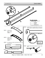
Summary of Contents for SHUR COVER

Page 1: ...Sheeting System w SMART3 P N 1127925 Rev B ...

Page 2: ...nd delivering repaired or replacement products from our factory to the owner will be paid by us If the product returned is found in our judgement to be non warrantable the owner will be contacted to authorize repair work purchase of a replacement product or return of the product all of which will be at the owner s expense Payment authorization must be received by us before any non warrantable prod...

Page 3: ...ealers SAFETY INSTRUCTIONS To prevent rust paint all exposed metal such as weld seams and or metal exposed by grinding or cutting with corrosion resistant paint ShurCover Sheeting System P N 1127925 Rev B MESSAGE TO OWNERS SAFETY RUST PREVENTION Hardware Identification Box Preparation 1 Sheet Installation 2 3 Center Pole Drive Motor 4 Web Spool Drive Motor 5 8 SMART3 Wireless Receiver 9 13 System ...

Page 4: ... If sheet length and width do not match what is on paper do not proceed Call your local dealer or call Shur Co Customer Service at 44 0 1795 473499 Prepare body before installing ShurCover sheeting system Re move or grind any sharp edges smooth to prevent sheet damage To prevent rust paint all exposed metal such as weld seams and or metal exposed by grinding or cutting with corrosion resistant pai...

Page 5: ...le Make sure face of assembly is square to center pole STEP 6 Weld center pole plug assembly onto end of center pole NOTE Keyway must be 180 from 5mm hole cut to length 90 keyway hole center pole plug 6 5 x 3 5 Item Part Description 1 1123980 Center Pole Plug UK 2 1701354 U Clamp 3 ______ Center Pole 4 ______ Pulling Bar 5 ______ Fixing Bar 6 ______ Sheet not shown D 1700398 Self Drilling Screw 1 ...

Page 6: ... pole Install third U clamp and screw at center of center pole STEP 8 Fasten pull bar to sheet with self drilling screw Align hole in sheet with hole in bar and secure Pull sheet tight and repeat on other end STEP 9 Repeat step 7 for fixing bar STEP 10 Place sheet on top of box with fixing bar hanging over right side of box Move sheet forward or backward until center pole insert plug is 75mm from ...

Page 7: ...6 Key Stock 1 1 4 B 1705353 Machine Screw M6 x 10 G 1705551 Flanged Cap Screw M6 x 16 I 1705550 Carriage Bolt M8 x 1 25 x 50 N 1705355 Cap Screw M10 x 1 5 x 150 P 1705349 Nylon Lock Nut M8 x 1 25 Y 1705350 Lock Washer M10 Z 1705347 Fender Washer 10 5mm x 30mm 2 5 6 STEP 1 Align holes in pivot arm with holes in center pole drive and fasten loosely with screws G STEP 2 Loosely fasten bushing and cam...

Page 8: ...Webbing 18m x 25mm Rear Trailer 12 1705581 ShurCover Decal C 1705371 Flanged Cap Screw M5 x 12 F 1705378 Self Tapping Screw 5 16 x 3 4 J 1700400 Self Tapping Screw 3 8 x 1 M 1705370 Cap Screw M10 x 60 O 1705461 Cap Screw M12 x 130 Q 1704931 Flanged Lock Nut 5 16 S 1700407 Hex Nut 3 8 U 1705361 Lock Nut M10 V 1705373 Lock Nut M12 W 1700434 Lock Washer 3 8 1 4 5 2 6 7 8 NOTE Steps 1 and 2 are for pr...

Page 9: ...with side of trailer or edge of mounting bracket 300mm edge of bracket edge of trailer spool bracket pull bar STEP 4 Fasten spool web guide to spool bracket with six screws C spool bracket spool web guide STEP 3 Fasten spool roller to spool bracket with M12 cap screw O and lock nut V spool bracket spool roller STEP 5 Determine location for spool bracket on front of box NOTE Custom bracket may be r...

Page 10: ...tallwebspoolandplasticwasherintospoolbracket Secure with impact wrench and screws F spool bracket plastic washer web spool top view spool bracket NOTE Use lock washers and nuts if possible Minimum wall thickness of 4 75mm is required when using self tapping screws J without lock washers W and nuts S STEP 5D Secure spool bracket to trailer with impact wrench and four self tapping screws J spool bra...

Page 11: ...ure with M8 x 120 cap screw and lock washer Tighten screws STEP 9 Route webbing through spool bracket web guide and insert bushing spacers into loops spool bracket web guide insert bush ing spacers into loops webbing STEP 8 Rotate web spool so M8 x 120 screw is facing forward Remove screw and loosen other two screws so two bushing spacers can be removed web spool remove bushing spacers M8 x 120 ca...

Page 12: ...s STEP 2 Using holes on receiver as guide mark and drill four 5mm holes manual switch wireless receiver driver side of front skin holes in receiver Item Part Description 1 1126867 SMART3 Remote 2 1128008 Jumper Wire Spool Standard 300mm 1128009 Jumper Wire Arm Standard 7000mm 1128010 Jumper Wire Spool Reverse Roll 1250mm 1128011 Jumper Wire Arm Reverse Roll 400mm 3 1127919 SMART3 Wireless Receiver...

Page 13: ...ss receiver Secure wire to bottom of spool bracket with 5 8 wire clip and screw E Secure to gear box with 1 2 wire clip and screw B Secure wire to trailer with 5 8 wire clips and self drilling screws E hole in trailer spool motor wireless receiver wireless receiver white white black black green green secure 3 conductor jumper wire w 5 8 wire clips screws E STEP 5A Secure wire to motor with 1 2 wir...

Page 14: ...h red lead placing as close as possible to power source SKIP TO SYSTEM SETUP STEP 8 Determine mounting location for wireless receiver NOTE Receiver has manual switch Locate where easily accessible and safe to operate sheet typically on driver side of front skin where it can be reached without climbing on trailer to 24V power supply wire clips screws STEP 6 Repeat steps 4 through 5 for center pole ...

Page 15: ...MART3 Wireless Receiver continued rubber grommet three wires hole in bracket drilled hole hole in trailer wireless receiver grommet STEP 11 Pull all three wires out of rubber grommets on bottom of receiver bracket Insert two 1 plugs into rubber grommets Verify wire lengths before drilling holes Dual con ductor red and black wire must reach 24V DC power supply Two marked 3 conductor wires must reac...

Page 16: ... red lead placing as close as possible to power source to 24V power supply wire clips screws STEP 15 Connect jumper wire between wireless receiver wire mandel spool and wire conncected to spool motor Connect wire ends to matching colored wire ends STEP 17a Secure wire to motor gear with 1 2 wire clips and screws B fastening through existing holes in motor STEP 18 Route dual conductor red and black...

Page 17: ...ox wire for spool and center pole motors This will allow motor breaks to be energized released without running motors STEP 2 Install web guide blocks on side of box Install at correct height in reference to spool to extend life of webbing Dur ing operation webbing should be centered in openings when entering spool bracket web guide block web guide blocks align center hole in web guide w notch in s...

Page 18: ... hole in center pole motor is lined up with hole in drive sprocket Insert M10 x 45 cap screw K and secure with M10 nylon lock nut U STEP 6 Reconnect white quick disconnect for spool motor wire Press and hold close button Allow webbing to roll up on spool until 2430mm mark reaches bracket Two people may be needed to safely complete this step STEP 4 Stretch webbing and mark 2540mm from spool bracket...

Page 19: ...r pole motor Press and hold Open button this will release motor breaks Unwind any remaining webbing from spool until marked bolt is in far left location Two people may be needed to safely complete this step STEP 9 Press and hold Open button until center pole reaches fully open position just short of reaching sheet stops This will protect sheet from damage from rubbing against stops NOTE Stop cente...

Page 20: ...TUPS ItemPart Description 1125374 Webbing Guide Kit Single Includes 2 4 2 of 5 6 7 1125375 Webbing Guide Kit Double Includes 1 3 3 of 5 6 7 1 1705554 Webbing Strap Guide Large 2 1705553 Webbing Strap Guide Small 3 1124992 Webbing Strap Guide Plate Large 4 1124989 Webbing Strap Guide Plate Small 5 1705556 Cap Screw M10 x 65 6 1705565 Nylon Lock Nut M10 7 1701176 Flat Washer 3 8 8 1805587 Front Stra...

Page 21: ... 1705450 Radial Ball Bearing 1 16 1124975 Center Pole Arm Plate Motor Side Standard 1124979 Center Pole Arm Plate Motor Side Reverse Roll Item Part Description 16 1124975 Center Pole Arm Plate Motor Side Standard 1124979 Center Pole Arm Plate Motor Side Reverse Roll 17 1124982 Bushing 1 2 x 1 2 18 1705352 Nylon Lock Nut M6 x 1 19 1124980 Center Pole Pivot Arm Low Rise 1124984 Center Pole Pivot Arm...

Page 22: ...1805587 Webbing 6m x 25mm Front 19 1805588 Webbing 12m x 25mm Rear Ridged 20 1805589 Webbing 18m x 25mm Rear Trailer 21 1124042 Spool Shaft Motor Adapter 22 1124819 Spool Shaft 3 4 x 5 3 4 23 1124002 Keystock 1 4 x 4 1 4 24 1705387 Socket Set Screw M6 x 12 25 1124001 Spool Plate 5 1 4 26 1124043 Bushing Spacer 3 16 27 1124820 Upper Spool Bearing Spacer 28 1705377 Spool Bearing 29 1124004 Spool Loc...

Page 23: ... Cap Screw M5 x 16 8 1705353 Machine Screw Pan Hd M6 x 10 9 1702926 Cap Screw 5 16 x 7 8 10 1705371 Flanged Cap Screw M5 x 0 8 x12 11 1126867 SMART3 Transmitter Remote 12 1127612 SMART3 Solenoid Cover Assy 13 1704309 Solenoid Gasket 14 1124029 Solenoid Bracket 3 4 2 9 5 10 Item Part Description 15 1704369 Trim Seal 16 1700428 Flat Washer 5 16 17 1700419 Nylon Lock Nut 5 16 18 1704721 Rubber Gromme...

Page 24: ......

Reviews: