P/N 1127925 Rev. B
13
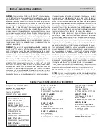
SMART3™ Wireless Receiver
- continued
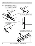
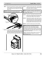
STEP 16
: Route
3
-conductor wire
marked for spool motor
through rubber grommet and to junction box on spool
motor. S
ecure wire to bottom of spool bracket with
wire clip and screw
D
. Secure wire to trailer with wire
clips and
self-drilling screws
.
3-
strand
wire
inside
of
trailer
shown
grommet
wire
clips
&
screws
NOTE:
For tipping
trailers, route female
SMARTwire™ on box to
trailer pivot, then back
to 24V power supply on
trailer frame. Add circuit
breaker if 24V power
supply is not already
protected with one. Align
breaker with red (+)
lead, placing as close
as possible to power
source.
to
24v
power
supply
wire
clips
&
screws
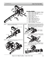
STEP 15
: Connect jumper wire between wireless receiver wire
mandel spool and wire conncected to spool motor.
Connect wire ends to matching colored wire ends.
STEP 17
a
:
Secure wire to motor gear with 1/2" wire clips and
screws
B
, fastening through existing holes in motor.
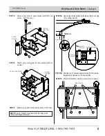
STEP 18
: Route
dual-conductor
red (+) and
black
(-) wires
to
24V power
supply and connect in best way
. Secure
wire
with wire-clips and self-drilling screws.
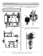
STEP 17
: Repeat steps
15 to 16 for
center pole drive motor,
securing wire to box with wire clips and M6 screws.
lock
pin
white
white
black
black
green
green
NOTE: Use care to
prevent damage to front
skin while securing wire
clips and drilling holes.
wire
clip
holes
in
motor
B
Summary of Contents for SHUR COVER
Page 1: ...Sheeting System w SMART3 P N 1127925 Rev B ...
Page 24: ......

