Precautions and Preparation
2
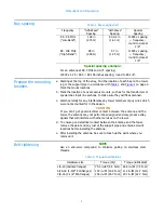
Bay spacing
Special spacing example:
For an antenna at 99.3 MHz and 0.75 spacing:
11803 x 0.75 / 99.3 = 89.146 inches spacing; round to 89-1/8".
Prepare the mounting
location.
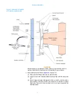
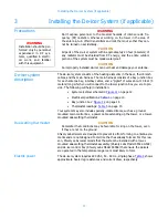
a. Starting at the top of the array, find the location of each bay on the tower
leg or the support pipe in accordance with
Mark the mount locations.
b. Mark the location of any accessory mounts, such as for the transformer or
special coax input line sections, to make sure they will fit as planned.
c. Watch carefully for any interferences by tower members or guy wires which
were not accounted for in the design.
CAUTION
If you don't get good electrical contact between the antenna and the
tower, the antenna may not perform as designed and may produce stray
signals that will interfere with other services on the tower.
d. To ensure good electrical contact between the antenna and the tower,
remove the paint and any rust at the support pipe and antenna mount
locations before installing the antenna.
e. After installing the antenna, be sure to touch up the paint where you
removed it.
Bolt tightening
NOTE
Use an anti-seize compound to minimize galling on stainless steel
threads.
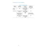
Table 1. Bay spacing chart
Frequency
"0.85-Wave"
Spacing
"Half-Wave"
Spacing
Special
Spacing
88 - 98 MHz
("Low-Band")
108 in
(2.74 m)
63-1/2 in
(1.61 m)
11803 x spacing
÷ frequency ;
round to closest
1/8"
98 - 108 MHz
("High-Band")
98 in
(2.49 m)
57 in
(1.45 m)
11803 x spacing
÷ frequency ;
round to closest
1/8"
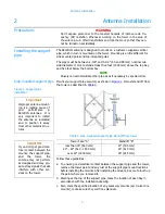
Table 2. Torque specifications
Hardware size
Torque (dry)
Torque (lubricated)
1/4-20 (radome flanges)
75.2 in-lbf (8.5 N-m) 63.9 in-lbf (7.2 N-m)
5/16-18 (1-5/8" EIA flanges)
132 in-lbf (14.9 N-m) 112 in-lbf (12.7 N-m)
3/8-16 (3-1/8" EIA flanges)
236 in-lbf (26.7 N-m) 201 in-lbf (22.7 N-m)


