background image


68 

5.6.3 

Closing the Application 

Clicking the 

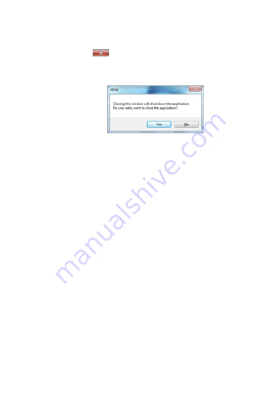
  icon in the recording parameter settings window displays a 

shutdown confirmation dialog box (Fig. 5-32). 

To exit the application, click [Yes]. 

To cancel the exit, click [No]. 

For instructions on how to log out, see 4.4 Logging In and Out of Windows. 


Fig. 5-32 Shutdown Confirmation Dialog Box 


Summary of Contents for Hyper Vision HPV-X2

Page 1: ...High Speed Video Camera Hyper Vision HPV X2 Instruction Manual Read the instruction manual thoroughly before you use the product Keep this instruction manual for future reference 347 07040 May 2015...

Page 2: ......

Page 3: ...ject to export control regulations of the nation based on Part2 of NSG guideline 5 B 3 Please contact sales agent or representative of Shimadzu should you have any question Notice Information in this...

Page 4: ...eath Caution Indicates a potentially hazardous situation which if not avoided may result in minor to moderate injury or equipment damage The following symbols are used in this manual Indicates an acti...

Page 5: ...oduct on a shaky table or inclined surface It may fall or tip resulting in injury Do not place heavy objects on the product Do not place anything 2 kg or heaver on the product This may cause the produ...

Page 6: ...ound wire This product is grounded via a 3 wire power cable equipped with a ground wire Be sure to insert this cable in a socket that is equipped with a ground terminal Failure to do so may result in...

Page 7: ...resentative Avoid operation in strong electromagnetic fields Do not use the product in locations subject to strong electromagnetic fields This may result in incorrect or abnormal operation Do not put...

Page 8: ...tting off the power supply cannot be performed quickly Inspection and Maintenance Warning Before performing servicing pull out the plug Before performing servicing such as wiping off dirt pull out the...

Page 9: ...abnormality is discovered such a smell of something burning or an unusual fan noise unplug the power unit Before using the instrument again inspect it and if necessary contact a Shimadzu field enginee...

Page 10: ...hine user 1 A Fixing to a tripod is insufficient and the camera falls and a hand or a foot is inserted The camera is fixed tightly at a fixed screw hole in a tripod attaching area Reference P 10 Opera...

Page 11: ...ded from the warranty even if they occur during the warranty period 1 Improper product handling 2 Repairs or modifications performed by parties other than Shimadzu or Shimadzu designated service compa...

Page 12: ...nance All supplemental program module for upgrades and enhancements furnished to you shall be deemed to be part of the SOFTWARE and subject to the terms and conditions set forth in this Agreement 5 LI...

Page 13: ...bility of Replacement Parts After Sales Service If any problem occurs with this product perform an inspection and take appropriate corrective action as described in 6 1 Troubleshooting If the problem...

Page 14: ...886 659 6 166 768 6 546 148 6 943 838 5 887 049 6 175 383 6 549 235 6 944 352 5 909 026 6 326 230 6 555 842 6 980 230 5 929 800 6 346 700 6 570 617 7 002 626 5 949 483 6 373 050 6 606 122 7 019 345 5...

Page 15: ...iew 1 2 Names and Functions of Components 3 2 1 Instrument Composition 3 2 2 Control Computer Application Functions 5 2 3 Names and Functions of Parts Camera Head 7 2 4 Names and Functions of Parts Po...

Page 16: ...hronized Recording 52 5 5 Playing Back Images 55 5 5 1 Setting Playback Parameters Viewer Operations 55 5 5 2 Playing Back Images 60 5 6 Image File Management and System Shutdown 61 5 6 1 Image File O...

Page 17: ...ions Key Features Records serial images maximum 256 frames in HP mode or maximum 400 X 250 pixels 100 000 pixels in FP mode at ultra fast speeds maximum ten million frames per second High performance...

Page 18: ...2...

Page 19: ...mes and Functions of Components 2 Names and Functions of Components 2 1 Instrument Composition The HPV X2 comprises the following units and parts When unpacking make sure that all of these items are i...

Page 20: ...sold separately Table 2 1 List of Components No Part Name Q ty 1 Camera head 1 2 Power unit 1 3 Ethernet cable 1 4 Power cable 1 5 AC cable For US or For EU 1 6 Control computer sold separately 1 7 I...

Page 21: ...les and perform other operations Image monitor image display area Displays recorded images and live images Playback parameter settings area This area has functions for setting up the parameters for pl...

Page 22: ...ecifying recording parameters Recording parameters are specified via REC Fig 2 2 and I O PORT Fig 2 3 windows It also starts recording and operates live functions Fig 2 2 REC Window Fig 2 3 I O PORT W...

Page 23: ...epts Nikon F mount compatible lenses The following figures show the camera head and its parts Fig 2 4 Camera Head Rear view of camera head 4 Standby input connector BNC 2 Video output connector 3 AUX...

Page 24: ...the power supply cable 2 Video output connector Connector used to connect the video cable It outputs a video NTSC PAL signal of live images 3 AUX output connector two BNC connectors Connector used to...

Page 25: ...Illuminates green when a synchronization cable is connected 7 LAN cable connector Ethernet connector used to connect the LAN cable 8 Synchronization cable connector Connector used to connect the sync...

Page 26: ...switched ON 2 Power switch Switches the entire camera system ON OFF 3 AC cable connector Connects the AC cable that supplies power to the power unit 4 Power cable connector Connects the power cable th...

Page 27: ...meras External Trigger Input Two channels TRIGIN STANDBY TTL level 5 V capable of either positive or negative polarity Recording Mode Internal trigger external trigger continuous trigger Optional Outp...

Page 28: ...and Control PC Approx 2 m Length of Power Cable Between Camera and Power Unit Approx 2 8 m 1 Shimadzu does not guarantee that all F mount lenses can be attached 2 The recording speed is a reference va...

Page 29: ...ables be sure to switch the power OFF Failure to do may cause instrument damage If the LAN cable between the camera head and control computer is routed via a HUB connection be sure to use Gigabit Ethe...

Page 30: ...g and Removing Lenses Mounting the Lens 1 Remove lens caps from the lens and camera head Fig 4 2 Camera Head and Lens 2 Firmly hold the lens and align the lens with the camera head mount Fig 4 3 Mount...

Page 31: ...ens so that it fits without leaving a clearance between the lens and camera head mount Failure to do so may result in damage Fig 4 4 Mounting the Lens 2 4 Turn the lens counterclockwise until you hear...

Page 32: ...achment of a regular F mount lens However the camera may be connected to various other optical systems depending on the user s specific camera application When connecting to other optical systems such...

Page 33: ...nses with an Aperture Ring If using a lens with an aperture ring align the aperture dial on the front of the camera head to CLOSE and use ring on the lens to adjust the aperture Fig 4 8 Lens with Aper...

Page 34: ...the aperture Fig 4 10 Lens without Aperture Ring Fig 4 11 Aperture Dial The process of adjusting aperture is the same for the aperture dial and ring However note that the markings only provide a guid...

Page 35: ...n and Out of Windows Logging In to Windows 1 Display the logon screen for Windows 2 In the logon screen enter shiva in the password field under HPV X and press the Enter key The Windows desktop appear...

Page 36: ...e keeping all windows unchanged For more details refer to the Windows User s Guide Selecting Restart All running Windows applications close the system is restarted and the Windows logon window is disp...

Page 37: ...nt network connection Also Shimadzu cannot guarantee the installation or normal operation of antivirus software or network security software on the control computer That is the responsibility of the c...

Page 38: ...22 3 After selecting the cameras to be connected from the list click IP address of the camera Copy 4 This lists IP addresses for cameras being connected in IP address of the camera field...

Page 39: ...camera is connected to field select the IP address of the computer After selecting the computer IP address click OK to finish registration 4 6 2 Procedure for Changing the IP Address of the Camera 1...

Page 40: ...Clicking Search cameras on the network lists all cameras on the network In the list select the camera IP address to change 3 After selecting the camera IP address to change click IP address of the ca...

Page 41: ...eparations for Operation 4 The following window is displayed Change the IP address and subnet mask settings as desired and click OK 5 Finish the procedure by verifying that the corresponding camera IP...

Page 42: ...ows The control computer is switched OFF 4 Hold down the power button on the power unit for three seconds to switch OFF power to the camera system Fig 4 13 Viewer Window with No Connected Cameras 4 7...

Page 43: ...power to the camera system Fig 4 14 Recording Parameter Settings Window Fig 4 15 Shutdown Confirmation Dialog Box Clicking or closes the application but not Viewer being run for file operations Close...

Page 44: ...28...

Page 45: ...n 5 2 Camera Settings and thereafter See 5 2 Camera Setup See 5 3 Illumination Setup See 5 4 2 Adjusting Exposure See 5 4 3 Recording Images See 5 4 3 Recording Images See 5 4 4 Synchronized Recording...

Page 46: ...exposure time decreases as the recording speed increases in such a way that a greater amount of light is required to achieve appropriate exposure After referring to 5 4 2 Adjusting Exposure set up il...

Page 47: ...by a preset time This does not need to be input for the internal trigger mode Internal external trigger mode External STANDBY or continuous external trigger mode R External STANDBY These modes automa...

Page 48: ...osure time for live images P 44 LIVE Displays live images P 45 REC Records images P 45 Selecting the Camera CAMERA This displays the name of the currently active camera Clicking CAMERA allows selectin...

Page 49: ...Setting File Clicking Save Setting File displays a window for saving files Fig 5 5 Enter a file name and click Save to save the current recording parameter settings with the specified file name For mo...

Page 50: ...pect to trigger input in images and specify settings for saving metadata for image files See 5 7 2 Metadata in Image Files Then click OK to apply the specified settings Fig 5 6 Window for Selecting th...

Page 51: ...The Internal mode does not require a standby or trigger signal input These signals are automatically generated within the camera In the Internal mode the time between clicking REC and when recording...

Page 52: ...ndby mode waiting for a standby signal About 850 ns after the standby signal is input it starts waiting for the trigger signal After the trigger signal is received it records the specified number of f...

Page 53: ...it immediately starts waiting for input of the next standby signal to repeat the process Continuous external trigger mode R External TRIG This mode allows repeatedly recording images using the extern...

Page 54: ...IN This mode allows repeatedly recording images using the external SYNCIN mode Clicking REC puts the camera in standby mode waiting for a standby signal About 850 ns after the standby signal is input...

Page 55: ...for adding recording speeds to the recording speed selection list 1 Display the window for editing the recording speed selection list Fig 5 11 2 In the field to the right of the Add button enter the r...

Page 56: ...ist Fig 5 11 2 Clicking Default displays a confirmation dialog box 3 Click Yes Clicking Yes resets the LIST values to default settings Default values are 100 ns 200 ns 500 ns 1 000 ns 2 000 ns 5 000 n...

Page 57: ...ure time selection list 1 Display the window for editing the exposure time selection list Fig 5 12 2 In the field to the right of the Add button enter the exposure time setting to be added to the list...

Page 58: ...en 200 ns and 300 ns less than the recording speed setting SPEED setting 300 ns can be selected Setting External Signal Trigger Polarity in TRIGGER POLARITY This setting is not necessary for the trigg...

Page 59: ...trigger input and the remainder after the trigger input until a total of 128 frames are recorded including the 88 frames from after the trigger Trigger input 40 Enter the trigger point setting values...

Page 60: ...for Live Images in LIVE EXPOSE Select this setting in the LIVE EXPOSE field The default live image exposure time setting after initial startup is selectable from 200 ns 500 ns 1 000 ns 2 000 ns 5 000...

Page 61: ...election list Fig 5 14 2 Click Default to display a confirmation dialog box 3 Click YES to initialize the live image exposure time selection list or NO to not initialize the list Clicking YES resets t...

Page 62: ...isplays eleven modes EXPOSE REC Outputs the starting point of exposure periods for each frame during recording Nothing is output during standby EXPOSE LIVE Outputs the starting point of exposure perio...

Page 63: ...in STANDBY DELAY STATUS REC Outputs signal during recording from start of recording until the end of recording Does not include standby delay time even if specified in STANDBY DELAY Setting the Polari...

Page 64: ...re available either NTSC or PAL output In the VIDEO field select either NTSC or PAL 5 4 2 Adjusting Exposure To adjust exposure follow the procedure below and use the internal trigger mode Internal 1...

Page 65: ...Back Images is displayed in the Viewer window Recording in the External Trigger Mode External TRIG This mode records frames before and after the trigger signal input In Selecting the Recording Mode i...

Page 66: ...recording remains in standby mode until a standby signal is input To not record or to stop recording before it is finished click REC STOP After the external signal standby OFF input and recording fin...

Page 67: ...signal When the trigger signal is input it records the specified number of frames and reads the image data Then it immediately starts waiting for input of the next standby signal This process is then...

Page 68: ...he rear of the camera is removed then the synchronization signal input and output connectors can be found Fig 5 17 Rear of the Camera No Part Name Description Synchronization signal output connector P...

Page 69: ...cording Mode in REC MODE in 5 4 1 Setting Recording Parameters specify the external trigger mode External SYNCIN to use as the recording mode Then click REC The window in Fig 5 16 is displayed and the...

Page 70: ...hen it immediately starts waiting for input of the next standby signal This process is then repeated To not record or to stop recording before it is finished click REC STOP The image specified in Sele...

Page 71: ...e Description See Page Playback stop P 56 Moves one frame back forward P 56 Plays all or stops all P 56 Frame No Displays the current frame number P 56 Relative Time Since Trigger Input Relative time...

Page 72: ...ndividual Viewer Clicking the icon stops playback in all Viewers that are playing back image data Viewer Current Frame Number Display Displays the frame number of the currently displayed image is disp...

Page 73: ...lected grid lines are not displayed Frame Range Setting START STOP Set the first and last frames displayed during playback Selecting First Frame to Display FIRST DISPLAY Select the frame number of the...

Page 74: ...splay Mode Click the icon to switch between the following two window display modes Normal display Normal View Displays images normally in the Viewer Enlarged view Scope View Displays images magnified...

Page 75: ...ges can be displayed at higher magnification rates than 2 times by using the scope view function described in Window Display Mode to achieve 4 times magnification The Viewer window size can be changed...

Page 76: ...he icon again Fig 5 22 Detailed Information Confirmation Window 5 5 2 Playing Back Images Follow the procedure below to play back recorded images 1 Click the icon in the Viewer window 2 Set playback p...

Page 77: ...form file operations click the file operation list icon in Viewer and select the desired operation and image file 5 6 1 Image File Operations Fig 5 23 Viewer Window File Operation Area File Operation...

Page 78: ...les OPEN Up to eight Viewer windows can be displayed simultaneously Saving files SAVE Clicking Save displays a window for saving files For details see 5 6 2 Saving Image Files Converting files CONVERT...

Page 79: ...e anything else in the HPVX ini file The file conversion function is applied only to existing image files To convert the format of recorded images first save the recorded image as an image file Deleti...

Page 80: ...ecording data in 5 4 1 Setting Recording Parameters a folder named BMP JPEG AVI8 AVI24 TIFF or TIFF16 is automatically created at the same directory level as where the image file is saved and image da...

Page 81: ...cated DAT Format When Adding Comments and Resaving 1 Display the image that is to be saved with comments in the Viewer window Load the applicable image data as described in 5 6 1 Image File Operations...

Page 82: ...ations 2 Click SAVE from the file operation list icon to display the window for saving files 3 Since the converted image file is named based on the name of the DAT file being converted change the file...

Page 83: ...n the destination folder Then the converted image file is saved in these folders To not save the file click Cancel Fig 5 30 Window for Saving Files 2 SAVE Fig 5 31 Inserting Recording Time and Time Re...

Page 84: ...rding parameter settings window displays a shutdown confirmation dialog box Fig 5 32 To exit the application click Yes To cancel the exit click No For instructions on how to log out see 4 4 Logging In...

Page 85: ...value Systemtime type RecordVersion Fixed binary from beginning of file 4 bytes Setting value 5 HPV X Comment 0x1010 0x1001 0 1024 Setting value Character string ASCII SHIFT JIS carriage return code C...

Page 86: ...ng value 2 to 256 Trigger mode 0x3030 0x3004 0 16 Setting value Character string Internal E trig E stdby E sep Sync Recording mode 0x3030 0x3005 0 16 Setting value Character string CFP BFP BHP UBFA5 U...

Page 87: ...S STANDBY 9 STATUS TRIG 10 STATUS REC PortAuxout1Polarity AUXOUT1 logic 0x3030 0x3011 2 1 Setting value 0 NEG 1 POS PortAuxout1Delay AUXOUT1 delay time 0x3030 0x3012 0 24 Setting value Character strin...

Page 88: ...ddress Starting address for camera transmission 0x4040 0x400A 2 1 Setting value Starting address for camera transmission of images ReadSize Camera transmission size 0x4040 0x400B 2 1 Setting value Cam...

Page 89: ...ns 0x5050 0x5006 2 1 Setting value Character string Data gradations for pixel gain correction table for applicable recording mode IMAGE_INFO Type Image format type 0x6060 0x6001 2 1 Setting value 0 HP...

Page 90: ...ample FrameStart 1 FrameStop Playback stopping frame Example FrameStop 256 FirstDisplay Display frame Example FirstDisplay 1 Gamma Gamma correction factor Example Gamma 1 2 Brightness Brightness Examp...

Page 91: ...ut2Polarity NEG PortAuxout2Delay External output port 2 delay time in ns units Example PortAuxout2Delay 10 000 000 ns PortAuxout2Pulse External output port 2 signal width in ns units Example PortAuxou...

Page 92: ...g CameraName Camera name Example CameraName Camera1 REC_SETTING RecMode Recording mode setting Example RecMode 0 Setting value 0 Internal 1 External STANDBY 2 External TRIG 3 External SEPARATE 4 R Ext...

Page 93: ...0 STATUS REC PortAuxout1Polarity External output port 1 polarity setting Example PortAuxout1Polarity 0 Setting value 0 NEG 1 POS PortAuxout1Delay External output port 1 delay time setting Example Port...

Page 94: ...how to display version information If a camera is connected click the icon in the recording parameter settings window or activate an application window and press the F1 key to display the version info...

Page 95: ...hown in the playback window See Playback Window Display Settings in 5 5 1 Setting Playback Parameters Viewer Operations Recording parameters may have changed Check the recording parameters again Recor...

Page 96: ...y result in rusting or damage Avoid getting this product wet with water Failure to do so may result in rusting or damage Follow the procedure below to clean the camera head 1 Clean away any dust from...

Page 97: ...a Status Indicator 7 CONTRAST 59 File Management 5 Playing Back 57 POWER Cable 4 Power Switch 54 REC MODE 37 Recording Images 33 Saving Image File 66 Setting Playback Parameters 57 Standby Input Conne...

Reviews: