


Dobot M1 User Guide
3
Hardware
Installation
Issue V1.0.4 (2018-01-31)
User Guide
Copyright © Yuejiang Technology Co., Ltd
26
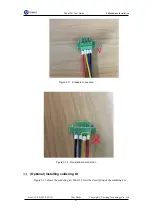
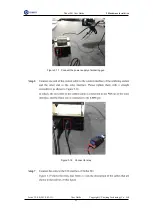
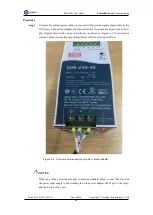
Figure 3.19 Relay cables
NOTICE
When relay is connected to I/O interface, the terminals of relay cannot be exposed
to the air, to avoid short circuit. For matching all I/O interfaces, terminals of relay
will be slightly longer. If that happens, you need to cut them to an appropriate
length.
If the relay is exposed to the air, a short circuit may occur. To avoid short circuit,
please wrap the relay with the insulating tape.
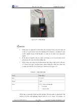
If the cables order of the relay is different from that shown in the red box of Figure
3.19 (from left to right: red, black, blue), please modify the cable order of the relay
to make sure that the order is the same as that shown in Figure 3.19.
Table 3.3 Cable description
Color
Description
Red
VCC_24V
Black
PGND
Blue
OUT1, Control soldering gun
0: Out-feed
1: Stop out-feed
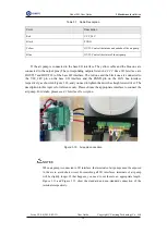
If the relay is connected to the base I/O interface. The blue cable is connected to the
output pin (The corresponding output listed in
is


