background image

11

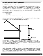
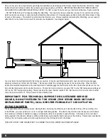
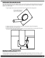
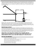
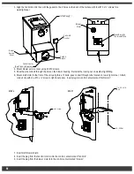
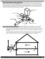
The diagrams below show typical installations through a basement window, crawl space, or wall.  Notice that the heat duct and return air 

duct do not contain any 90° elbows.  The use of 45° or less is advised for proper air delivery.
IF 10 INCH FLEX DUCT IS USED, IT MUST NOT BE EXPOSED TO THE OUTDOORS.  IT IS FOR INDOOR USE ONLY.
WARNING: RISK OF FIRE! DO NOT USE ANYTHING OTHER THAN 250° F-RATED FLEX DUCT!

GROUND FURNACE TO GROUNDING ROD AND LEG OF FURNACE!
IMPORTANT:  FOR TECHNICAL SUPPORT OR CUSTOMER SERVICE 

ISSUES, DO NOT RETURN TO THE STORE (THE STORE DOES NOT HAVE 

REPLACEMENT PARTS), CALL SHELTER FURNACE AT 1-800-875-4788.
TYPES OF INSTALLATION:

Your Shelter Furnace is designed to be a supplemental or central heating source for your home.  This wood/coal burning furnace may be 

installed parallel with a properly operating electric, gas, or oil-fired central furnace that is listed or certified in accordance with a nationally 

recognized safety standard within installation clearances as specified on the Shelter Furnace nameplate.  When in a parallel installation 

the static pressure of the central furnace plenum may not exceed .15 inches water column, and maximum setting on central furnace limit 

switch is 182° F.  With the SF3042 wood and coal burning furnace in an “Interconnection Arrangement” your Shelter Furnace should 

be upstream from the central furnace.  The Shelter Furnace warm air supply should never be connected to the return air for the central 

furnace.  A QUALIFIED INSTALLER SHOULD PERFORM INSTALLATION.

CENTRAL DUCT CONNECTIONS:

  A qualified professional should do the installation.  Maximum run should be 25 feet.  A duct run 

in excess of 25 feet will greatly restrict the air flow and heat output, therefore is not recommended.  When connecting the SF3042 to a 

central duct system, avoid 90° elbows.  As with any furnace, the more turns and branches in the ducting limit the airflow delivery.  DO 

NOT USE FLEX DUCT OUTSIDE.
Run 10 inch insulated galvanized hot air duct from the outside furnace through a window or wall of the house.  Once inside, you may use 

250 degree rated insulated flexible hot air duct, to the central duct system for the home.  Connect the duct with a 45° elbow or at an angle 

so the hot air from the SF3042 is delivered down stream.  This will ensure proper airflow into the duct system.  Avoid delivering the hot air 

through the air conditioning coil, as this will cause an obstruction, reducing the amount of heat output.  DO NOT REDUCE THE SIZE OF 

THE HOT AIR DUCT.  As with any furnace, longer runs and more turns and branches in the ducting greatly reduce the airflow and heat 

output.  Use of 90° elbows is not recommended.
The 12 inch cold air return duct must run to the house to prevent pressurization of the home.  Failure to connect the cold air return will 

cause the furnace not to operate.  NEVER REDUCE THE SIZE OF THE RETURN.  Reducing the size of the cold air return will restrict 

the hot air flow and put excess pressure on the blower motor.  You may terminate the cold air return where you enter the house.  This will 

provide adequate circulation within the home.  See diagram.

RETURN AIR DUCT

SUPPLY DUCT

OPEN/CLOSE 

RETURN DAMPERS

3 PLACES

BACKDRAFT DAMPERS

Return Air Duct

Backdraft Dampers

Open/Close

Return Dampers

3 Places

Supply Duct

Summary of Contents for SF3042

Page 1: ...FURNACE WOOD AND COAL BURNING OUTDOOR FURNACE MODEL SF3042 Manufactured by Shelter Furnace 10950 Linpage Place Saint Louis MO 63132 1 800 875 4788 MADE IN USA REVISION I JUNE 2012 Tested to UL391 Sta...

Page 2: ...from the home this would give maximum airflow and provide the highest efficiency Transportation Damage Every effort has been made to ensure that your Shelter Furnace will arrive in perfect condition...

Page 3: ...nnection 12 General Operation 13 First Wood Fire 13 Loading Wood 13 First Coal Fire 14 Fuel Recommendations 14 Disposal of Ashes 15 Heat Dump and Fuse Link System 15 Draft Blower and Spin Draft 16 Cre...

Page 4: ...within the home and amount of fuel We have incorporated all of these features as standard equipment offering you the most efficient durable and affordable appliance possible Abnormally cold weather c...

Page 5: ...building or peak of the roof within a horizontal distance of 10 feet The 2 foot height does not include the cap See diagram below Class A HT 2100 All Fuel 6 inch Chimney Pipe is required for optimum...

Page 6: ...reaches the selected temperature on the wall thermostat it will disengage the draft motor and the fire in the firebox will reduce to a low burn until the thermostat calls for another heat cycle The fa...

Page 7: ...oor furnace 4 After all the chimney components are installed including the cap follow the diagram below to caulk around the chimney pipe as well as around the outer edge of the anchor plate Chimney Lo...

Page 8: ...Care KEEP WOOD COVERED AT ALL TIMES This cannot be over emphasized Wood stored stacked uncovered exposed to rain and snow has a higher moisture content causing the formation of creosote excess smoke a...

Page 9: ...er leave the ash or fuel door open in an attempt to regulate the fire This will overheat the furnace and void the warranty Do not connect this unit to a chimney flue serving another appliance Refer to...

Page 10: ...w to right inner panel Insert plug into control center marked draft motor 7 Insert draft blower shield 8 Insert the plug from the fan limit control into the control center marked fan limit 9 Insert th...

Page 11: ...properly NEVER draw cold outside air into the blower housing By doing so the furnace s heat chamber will not reach the necessary temperature to heat the home The duct work should be designed so the ex...

Page 12: ...NNECTIONS A qualified professional should do the installation Maximum run should be 25 feet A duct run in excess of 25 feet will greatly restrict the air flow and heat output therefore is not recommen...

Page 13: ...hout ductwork When there is no duct system to connect to the hot air flex duct keep in mind You must separate the hot air duct from the cold air return Ideally locate each at opposite ends of the home...

Page 14: ...ll thermostat and draft blower cover to a comfortable setting See diagram on page 16 spin draft Ash pan must remain out of furnace during operation NOTE Your new Shelter Furnace is capable of producin...

Page 15: ...be sure to leave a red spot in the center of the bed This hot spot will help ignite the gases given off the new charge A deep charge will give a more even heat and a longer fire It may take up to a co...

Page 16: ...0 F The heat sensitive fuse link located within the top of the heat chamber causes the lid to open allowing the excess heat to escape This safety feature is designed to activate before any extreme hea...

Page 17: ...t creosote residue accumulates on the flue lining When ignited this creosote makes an extremely dangerous fire in the chimney The chimney connector and the chimney should be inspected at least twice m...

Page 18: ...ns of wear and replace as needed Check the heat duct and cold air return to be sure they have not become loose or been damaged If so tighten or replace as needed Check ductwork for any air leaks Remov...

Page 19: ...DO NOT CONNECT DUCTWORK SO THAT A REVERSE FLOW IS POSSIBLE OPERATE THE GAS OIL ELECTRIC FURNACE PERIODICALLY TO ENSURE THAT IT WILL OPERATE SATISFACTORILY WHEN NEEDED CERTIFIED FOR INSTALLATION WITH...

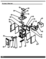
Page 20: ...COVER MIT CONTROL BOX ER BACK PANEL ER TOP PANEL GE AT DUMP LID INNER DUMP LID T DUMP SPRING BRACKET INE SCREW OUTER PANEL P PANEL C CHANNEL T AND RIGHT INNER ER SIDE PANEL LEFT DOOR ASSEMBLY R SKIN B...

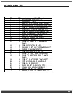
Page 21: ...9 FC000 78 INNER TOP PANEL 1 10 FCH1800 HINGE 1 11 FC000 81 HEAT DUMP LID INNER PANEL 1 12 SF42 33 HEAT DUMP LID 1 13 FCHDSB HEAT DUMP SPRING BRACKET 5 14 FCFLAB MACHINE SCREW 1 15 SF42 40 TOP OUTER P...

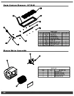
Page 22: ...3 1 8 X 1 11 2 1 3 9 10 7 4 11 5 6 ITEM ITEM NUMBER ITEM DESCRIPTION TOTAL QUANTITY 1 SFSR4 Cast Rail 4 Slot 2 2 SFSG Cast Grate Shaker 4 3 SFCB4 Control Bar Shaker 4 1 4 SFCBL Control Bar Link Shaker...

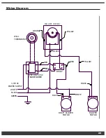
Page 23: ...B FAN LIMIT CONTROL WALL THERMOSTAT 120V AC 24V AC TRANSFORMER RELAY DRAFT BLOWER MOTOR BLOWER MOTOR BLACK 120V AC POWER SUPPLY WHITE BLACK GREEN BLACK WHITE YELLOW RED RED RED YELLOW BLACK ORANGE WIR...

Page 24: ...23 Troubleshooting...

Page 25: ...24...

Page 26: ...25...

Page 27: ...26...

Page 28: ...27...

Page 29: ...or gaskets are excluded from this warranty In order to exercise the aforementioned warranty a certified professional must determine the appliance part to be defective He or she must submit a written s...

Page 30: ......

Reviews: