Shel lab SVAC9-2 Installation And Operation Manual Download Page 18


18 | 

P a g e


INSTALLATION 


I

NSTALL THE 

S

HELVING


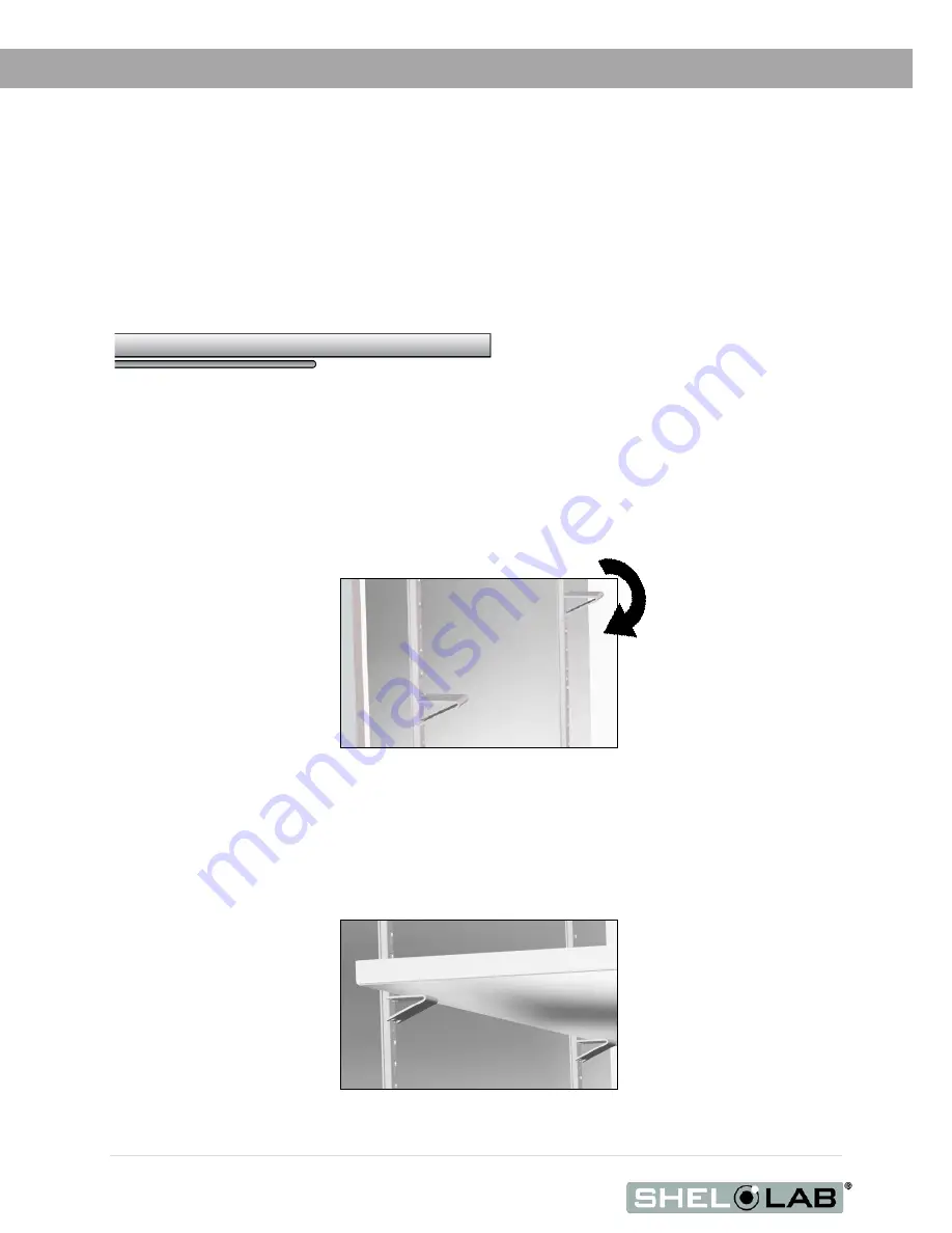
To ensure accurate temperature measurement, 

one shelf bottom must be in close proximity to the 

oven temperature probe

 extending out from the chamber back wall. Do not place the shelf in direct 

contact with the probe. 


1.


Install the shelf clips in the slots of the shelf standard mounting rails located on the sides of 

the chamber interior, four clips (4) per shelf. 

a.


Squeeze each clip, insert the top tab first, and then the bottom tab using a 

rocking motion. 


2.


Set the shelves on the clips. 

a.


Make sure the shelves are level. 

Installing Shelf Clips 

Rocking Motion 

Probe 

Shelf 

Summary of Contents for SVAC9-2

Page 1: ...Installation Operation Manual SVAC9 2 Vacuum Oven 230 Voltage...

Page 2: ...for many cleanroom applications the paint free exterior surfaces are corrosion resistant and help to prevent contamination from paint flecking and surface particle retention Special Quote SQ Number 91...

Page 3: ...onal industrial or educational use where the preparation or testing of materials is done at an ambient air pressure range of 22 14 31 3 inHg 75 106 kPa and no flammable volatile or combustible materia...

Page 4: ...ling 16 Leveling 17 Installation Cleaning 17 Install the Oven 17 Install the Shelving 18 Connect to the Vacuum Supply 19 GRAPHIC SYMBOLS 21 CONTROL OVERVIEW 23 OPERATION 27 Operating Precautions 27 Th...

Page 5: ...site specific standard operating procedure SOP covering each application and associated safety guidelines This SOP must be written and available to all operators in a language they understand Intended...

Page 6: ...EERING IMPROVEMENTS Sheldon Manufacturing continually improves all of its products As a result engineering changes and improvements are made from time to time Therefore some changes modifications and...

Page 7: ...oven temperature display Reference devices must meet the following standards Accurate to at least 1 C The device should be regularly calibrated preferably by a third party Temperature Probes Use a di...

Page 8: ...8 P a g e INTRODUCTION...

Page 9: ...rrier s procedure for claiming damage or loss 1 Carefully inspect the shipping carton for damage 2 Report any damage to the carrier service that delivered the oven 3 If the carton is not damaged open...

Page 10: ...et as well as a 3 8 Inch 9 52mm OD vacuum port fitting and purge vent intake fitting A screwdriver is required to access the plumbing cabinet Always disconnect the unit from its power feed before open...

Page 11: ...the model number and serial number of your unit to accurately assist you during support calls or emails Locate the unit data plate and record both numbers below for future reference The data plate is...

Page 12: ...12 P a g e RECEIVING...

Page 13: ...the required ambient condition for the oven are met page Error Bookmark not defined Check that the spacing clearance requirements are met page 14 Unit dimensions may be found on page 39 Check that a...

Page 14: ...ven and any walls or partitions for unobstructed airflow and cooling Allow at least 6 inches 150 mm of ventilation on the sides o Do not place objects on top of the oven o Leave at least 6 inches 150m...

Page 15: ...g or circuit failure A switch or circuit breaker must be used in the building installation to protect against overcurrent conditions o Required circuit breaker for the wall power source is 30 Amps A s...

Page 16: ...nection Removing the protective conductor will negate the oven s protections against potentially dangerous electric shocks and create a possible fire hazard LIFTING AND HANDLING The oven is heavy Use...

Page 17: ...during shipping Remove all wrappings and coverings from shelving prior to cleaning and installation Do not clean with deionized water See the Cleaning and Disinfecting topic in the User Maintenance se...

Page 18: ...not place the shelf in direct contact with the probe 1 Install the shelf clips in the slots of the shelf standard mounting rails located on the sides of the chamber interior four clips 4 per shelf a...

Page 19: ...ext page Cabinet Ports Vent port inch 6 35mm A purge gas supply line can be connected to this intake vent Vacuum Port KF 25 and 3 8 inch 9 52 mm Line Vacuum Connection Connect an external vacuum suppl...

Page 20: ...Valve control on the front of the oven is open o Optional An inert backfilling gas supply source may be connected to this port The maximum allowed pressure for a purge gas is 15 psi KF 25 Fitting Bac...

Page 21: ...courant alternatif I ON O OFF I indique que l interrupteur est en position marche O indique que le commutateur est en position d arr t Indicates the internal vacuum pump power switch and the vacuum di...

Page 22: ...22 P a g e GRAPHIC SYMBOLS...

Page 23: ...sets the heating cut off point for the OTL temperature limit system The OTL system prevents unchecked heating of the chamber For more details please see the Over Temperature Limit System description i...

Page 24: ...temperature set point Pressing and holding both buttons navigates from the Home Page to menu pages On the menu pages the buttons adjust calibration offsets and heating profile variables When starting...

Page 25: ...alve is open When the valve control is in the closed position fully clockwise the chamber is cut off from external atmosphere and any purge gas supply o The intake vent port must be closed before appl...

Page 26: ...26 P a g e CONTROL OVERVIEW...

Page 27: ...ble or combustible gases vapors liquids or fuel air mixtures in quantities that can become potentially explosive Outgassed byproducts may be hazardous to or noxious for operating personnel Vacuum pump...

Page 28: ...risk destroying the vacuum pump and damaging the integrity of the oven chamber Vacuum pumps and door gaskets should be selected based on the application or process Gasket types are resistant and vuln...

Page 29: ...re PID controlled heating pulse intensities and lengths are proportional to the difference between the measured shelf temperature and the current set point The frequency of pulses is derived from the...

Page 30: ...h to Reset button to reset the heating element power relays The oven display will not power up unless the relays are set Do not press the gray Reset button on the controller 2 Place the oven Power Swi...

Page 31: ...pe Doing so prepares the oven for setting the Over Temperature Limit 5 Set the Over Temperature Limit See page 35 The oven must be heated and under vacuum to perform this procedure Optional If you are...

Page 32: ...ant temperature set point on the second row to match your set point Holding down an arrow key causes the temperature to advance in increments of tens 10 rather ones 1 2 Release the Arrow key once you...

Page 33: ...uum Valve by turning it all the way counterclockwise to bring oven chamber under vacuum draw Hold at Vacuum 5 Keep the oven chamber under vacuum throughout the duration of your baking application to e...

Page 34: ...the back of the oven 3 Open the vacuum regulator on your supply system to begin evacuating the oven chamber Hold at Vacuum 4 Keep the oven chamber under vacuum throughout the duration of your baking...

Page 35: ...t done so already turn the Set Over Temperature Limit control dial clockwise to the maximum position 2 Turn the Over Temperature Limit control dial counterclockwise until the temperature controller di...

Page 36: ...et button If the OTL continues to interrupt heating of the oven chamber and there no obvious external sources of nearby heating autoclaves another oven depower the oven and allow the oven chamber to c...

Page 37: ...cise caution if cleaning the unit with alcohol or flammable cleaners Always allow the unit to cool down to room temperature prior to cleaning and make sure all cleaning agents have evaporated or other...

Page 38: ...when disinfecting Disinfect all surfaces in the chamber making sure to thoroughly disinfect the corners Exercise care to avoid damaging the sensor probes When disinfecting external surfaces use disin...

Page 39: ...ule Always calibrate to the industry or regulatory standards required for your application Suggested Temperature Calibration Set Up Continued on next page 1 Introduce a thermocouple probe from a refer...

Page 40: ...erature display readings If the readings are the same or the difference between the two 2 falls within the acceptable range of your protocol the display is accurately showing the chamber temperature T...

Page 41: ...nit i CA appears on the green mid display line and a number value on the red top line 5 Adjust the number value in the top display to match the offset value from step 2a using the arrow buttons 6 Save...

Page 42: ...ng the chamber temperature The temperature calibration procedure is now complete b See step 9 if a difference falls outside the acceptable range of your protocol again Reference Device 9 Repeat steps...

Page 43: ...especting the recommended wall clearances of 10 of the height width and depth of the inner chamber All indications are average values typical for units produced in the series We reserve the right to a...

Page 44: ...Operating Range Uniformity Ambient 15 to 220 C 6 of Set Point Stability 80 C 150 C 220 C 0 2 C 0 2 C 0 3 C Heat up Times from Ambient 25 C To 80 C To 150 C To 220 C 80 minutes 130 minutes 180 minutes...

Page 45: ...3450560 If you have the Part Number for an item you may order it directly from Sheldon Manufacturing by calling 1 800 322 4897 extension 3 If you are uncertain that you have the correct Part Number o...

Page 46: ...P O Box 627 Cornelius OR 97113 USA support sheldonmfg com sheldonmanufacturing com 1 800 322 4897 503 640 3000 FAX 503 640 1366...

Reviews: