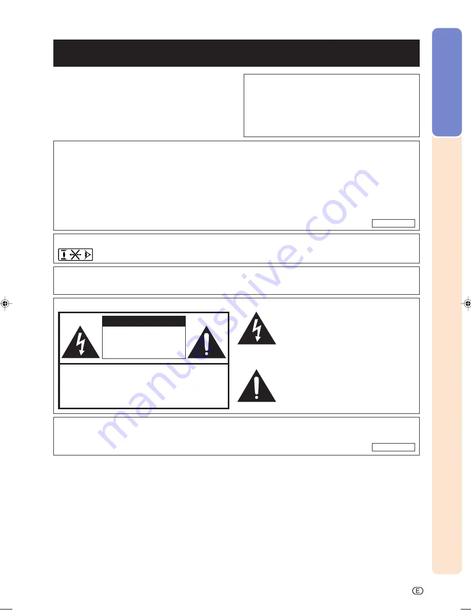
Sharp XV-Z12000 - Vision - DLP Projector Operation Manual Download Page 2

Introduction

-1

Before using the projector, please read this operation manual carefully.

There are two important reasons for prompt warranty registration of your new SHARP Projector, using
the REGISTRATION CARD packed with the projector.

1. WARRANTY

This is to assure that you immediately receive the full benefit of the parts, service and labor
warranty applicable to your purchase.

2. CONSUMER PRODUCT SAFETY ACT

To ensure that you will promptly receive any safety notification of inspection, modification, or
recall that SHARP may be required to give under the 1972 Consumer Product Safety Act, PLEASE
READ CAREFULLY THE IMPORTANT “LIMITED WARRANTY” CLAUSE.

WARNING:

High brightness light source. Do not stare into the beam of light, or view directly. Be especially
careful that children do not stare directly into the beam of light.

WARNING:

To reduce the risk of fire or electric shock, do not expose this product to
rain or moisture.

WARNING:

FCC Regulations state that any unauthorized changes or modifications to this equipment not
expressly approved by the manufacturer could void the user’s authority to operate this equip-
ment.

CAUTION: TO REDUCE THE RISK OF ELECTRIC SHOCK,

DO NOT REMOVE COVER.

NO USER-SERVICEABLE PARTS EXCEPT LAMP UNIT.

REFER SERVICING TO QUALIFIED SERVICE

PERSONNEL.

The lightning flash with arrowhead symbol,
within an equilateral triangle, is intended to
alert the user to the presence of uninsulated
“dangerous voltage” within the product’s
enclosure that may be of sufficient magnitude
to constitute a risk or electric shock to
persons.

The exclamation point within a triangle is
intended to alert the user to the presence of
impor tant operating and maintenance
(servicing) instructions in the literature
accompanying the product.

Introduction

ENGLISH

CAUTION

RISK OF ELECTRIC SHOCK.

DO NOT REMOVE SCREWS

EXCEPT SPECIFIED USER

SERVICE SCREWS.

See bottom of actual set.

U.S.A. ONLY

U.S.A. ONLY

IMPORTANT

For your assistance in reporting the loss or theft of your
Projector, please record the Serial Number located on
the bottom of the projector and retain this information.
Before recycling the packaging, please be sure that
you have checked the contents of the carton thoroughly
against the list of “Supplied accessories” on page 

14

.

Model No.: XV-Z12000

Serial No.:

XV_Z12000_E_US_p01_04.p65

03.9.24, 1:53 PM

1

Summary of Contents for XV-Z12000 - Vision - DLP Projector

Page 1: ...OPERATION MANUAL MODE D EMPLOI MANUAL DE OPERACION MANUAL DE OPERAÇÃO XV Z12000 TOR TEUR TOR OR ENGLISH 1 96 FRANÇAIS 1 95 ESPAÑOL 1 94 PORTUGUÊS 1 94 ...

Page 2: ...y approved by the manufacturer could void the user s authority to operate this equip ment CAUTION TO REDUCE THE RISK OF ELECTRIC SHOCK DO NOT REMOVE COVER NO USER SERVICEABLE PARTS EXCEPT LAMP UNIT REFER SERVICING TO QUALIFIED SERVICE PERSONNEL The lightning flash with arrowhead symbol within an equilateral triangle is intended to alert the user to the presence of uninsulated dangerous voltage wit...

Page 3: ...f not installed and used in accordance with the operation manual may cause harmful interference to radio communications However there is no guarantee that interference will not occur in a particular installation If this equipment does cause harmful interference to radio or television reception which can be determined by turning the equipment off and on the user is encouraged to try to correct the ...

Page 4: ...Display Language 36 Turning the Power off 37 Keystone Correction and Vertical Size Adjustment 38 Menu Bar Items 40 Using the Menu Screen 42 Menu Selections Adjustments 42 Menu Selections Settings 44 Adjusting the Picture 46 Selecting the Picture Position 46 Adjusting Image Preferences 47 Selecting the Gamma Position 47 Selecting the C M S Position 48 Special Settings 48 IP Mode 49 Emphasizing the ...

Page 5: ...on 72 Selecting the Transmission Speed RS 232C 72 Reversing Inverting Projected Images 73 Displaying the Adjustment Settings 74 Appendix Maintenance 76 Cleaning the Ventilative Holes 77 Maintenance Indicators 78 Regarding the Lamp 80 Lamp 80 Caution Concerning the Lamp 80 Replacing the Lamp 80 Removing and Installing the Lamp Unit 81 Resetting the Lamp Timer 82 Connecting Pin Assignments 83 RS 232...

Page 6: ...ource indicated on the marking label If you are not sure of the type of power supply to your home consult your product dealer or local power company For products intended to operate from battery power or other sources refer to the operating instructions 12 Grounding or Polarization This product is equipped with a three wire grounding type plug a plug having a third grounding pin This plug will onl...

Page 7: ...soft Corporation in the United States and or other countries PC AT is a registered trademark of International Business Machines Corporation in the United States Adobe Acrobat is a trademark of Adobe Systems Incorporated Macintosh is a registered trademark of Apple Computer Inc in the United States and or other countries All other company or product names are trademarks or registered trademarks of ...

Page 8: ...tion Be sure that the intake vent and the exhaust vent are not obstructed If the cooling fan becomes obstructed a protection cir cuit will automatically put the projector into the standby mode This does not indicate a malfunction Remove the projector power cord from the wall outlet and wait at least 10 minutes Place the projector where the in take and exhaust vents are not blocked plug the power c...

Page 9: ...anguages If you prefer using Acrobat Reader for languages other than those included in the CD ROM please download the appropriate version from the Internet Accessing the PDF Manuals For Windows 1 Insert the CD ROM in the CD ROM drive 2 Start up Explore 3 Double click the CD ROM drive 4 Double click the MANUALS folder 5 Double click the language name of the folder that you want to view 6 Double cli...

Page 10: ...udio cable 4 Plug the power cord into the AC socket of the projector and into the wall outlet Page 16 34 5 Remove the lens cap from the lens Page 10 7 Press on the remote control to select the INPUT 4 mode Page 35 On screen Display 8 Turn on the video equipment To INPUT 4 terminal To video out put terminal INPUT 4 button ON button The power indicator illuminates blue ON Adjust the height of the im...

Page 11: ...ll illuminate red Lamp indicator Illuminates blue indicating normal function Replace the lamp when the indicator illuminates red Power indicator Illuminates red when the projector is in standby When the power is turned on this indicator will illuminate blue 34 Adjustment foot Lens cap Intake vent 27 Adjustment foot 13 Remote control sensor Projector Front and Top View Part Names Numbers in refer t...

Page 12: ...nt Projector Rear View Using the Kensington Lock This projector has a Kensington Security Standard connector for use with a Kensington MicroSaver Security Sys tem Refer to the information that came with the system for instructions on how to use it to secure the projector Using the Terminal Cover When the projector is used on a desktop high mounted or ceiling mounted attach the terminal cover suppl...

Page 13: ...ion or returning to the default settings 35 INPUT buttons For switching to the respective input modes 69 RGB COMP button For switching to the respective input signal type 59 AUTO SYNC button For automatically adjusting images when connected to a computer 13 Remote control signal transmitters 62 RESIZE button For switching the screen size SIDE BAR SMART STRETCH etc 46 PICTURE POSITION button For se...

Page 14: ...r into the opening and lower the cover until it clicks in place Incorrect use of the batteries may cause them to leak or explode Please follow the precautions below Caution Insert the batteries making sure the polarities correctly match the and marks inside the battery compart ment Batteries of different types have different properties therefore do not mix batteries of different types Do not mix n...

Page 15: ... 3 0 m AN C3DV Note Some of the cables may not be available depending on the region Please check with your nearest Authorized SharpVision Service Center or Dealer Operation manual this manual TINS A970WJZZ SharpVision Manager operation manual TINS B097WJZZ CD ROM SharpVision Manager UDSKAA040WJZZ Lens cap attached PCAPH1056CESA Supplied accessories Optional accessories Terminal cover CCOVA1985CE03...

Page 16: ...Connections and Setup Connections and Setup ...

Page 17: ...sure to read the operation manuals of the devices to be connected before making connections This projector can be connected to Video equipment A VCR DVD player or other video equipment See page 17 A DVD player or DTV decoder See page 18 DTV is the umbrella term used to describe the new digital television system in the United States A computer using DVI to 15 Pin D sub adapter See page 22 A DVI cab...

Page 18: ...erminal 2 Connect the above cable to the video equipment S video cable to S video output ter minal Composite video cable to video out put terminal Note The INPUT 3 S VIDEO terminal uses a video signal system in which the picture is separated into color and luminance sig nals to realize a higher quality image To view a higher quality image use a com mercially available S video cable to con nect the...

Page 19: ...television system in the United States 1 Connect a component cable to the projector 2 Connect the above cable to the component video equipment Note When connecting the projector to the video equipment in this way select Com ponent for Signal Type in the Options menu or select the Component mode by pressing on the remote control See page 69 Set the Resolution of Special Modes to 480P during input o...

Page 20: ...and VD terminals may be used depending on the specifications of the DTV decoder connected to this pro jector Please refer to the operation manual of the DTV decoder for details To INPUT 1 or 2 terminals Connecting to RGB Video Equipment Using the DVI to 15 pin D sub Adaptor and the RGB Cable INPUT 5 1 Connect a DVI to 15 pin D sub adaptor to the projector 2 Connect the above adaptor to an RGB cabl...

Page 21: ...I to 15 pin D sub adaptor to the projector 2 Connect a 3 RCA to 15 pin D sub cable to the above adaptor Secure the connectors by tightening the thumbscrews 3 Connect the above cable to the video equipment Note Select the input signal type of the video equipment See page 69 3 RCA to 15 pin D sub cable Type AN C3CP 9 10 3 0 m DVI to 15 pin D sub adaptor Type AN A1DV 7 9 20 cm Optional accessories To...

Page 22: ...I cable commercially available Video equipment To INPUT 5 terminal To HDMI output terminal Connecting to Video Equipment with the DVI Output Terminal Using a DVI Cable INPUT 5 Use a DVI cable when connecting video equip ment with the DVI output terminal such as DVD players to INPUT 5 terminal 1 Connect a DVI cable to the pro jector 2 Connect the above cable to the video equipment Secure the connec...

Page 23: ...of the functions not to work When connecting the projector to a com puter in this way select A RGB for Sig nal Type in the Options menu or select the A RGB by pressing on the re mote control See page 69 A Macintosh adaptor may be required for use with some Macintosh computers Contact your nearest Authorized SharpVision Service Center or Dealer Depending on the computer you are us ing an image may ...

Page 24: ...connectors by tightening the thumbscrews Note Switch the signal type to either A RGB or D PC RGB depending on whether the computer output signal is analog or digi tal See page 69 Before connecting be sure to unplug the power cord of the projector from the AC outlet and turn off the computer to be con nected After making all connections turn on the projector and then the computer Be sure that the c...

Page 25: ... Play function This projector is compatible with VESA standard DDC 1 DDC 2B The projector and a VESA DDC compatible computer will communicate their setting requirements allowing for quick and easy setup Before using the Plug and Play function be sure to turn on the projector first and the con nected computer last Note The DDC Plug and Play function of this projector operates only when used in conj...

Page 26: ...nect an RS 232C cable to the projector 2 Connect the above cable to the computer Secure the connectors by tightening the thumbscrews Note Do not connect or disconnect an RS 232C cable to or from the computer while it is on This may damage your computer The RS 232C function may not operate if your computer terminal is not correctly set up Refer to the operation manual of the computer for details De...

Page 27: ...ojector rear projection etc connect a ø3 5 mm minijack cable commercially available or available as Sharp service part QCNWGA038WJPZ from the WIRED R C JACK on the top of the remote control to the WIRED REMOTE control input terminal ø3 5 mm minijack cable commercially available or available as Sharp service part QCNWGA038WJPZ To WIRED R C JACK To WIRED REMOTE control input terminal 26 Remote contr...

Page 28: ...t releases Once the adjust ment feet have locked in posi tion release the projector If the screen is at an angle the ad justment feet can be used to adjust the angle of the image Note The projector is adjustable up to approxi mately 5 degrees from the standard posi tion When the height of the projector is ad justed the image may become distorted keystoned depending on the relative positions of the...

Page 29: ...image is focused and adjusted to the desired size using the focus ring or zoom knob on the projector 1 The focus is adjusted by rotat ing the focus ring 2 Zooming is adjusted by mov ing the zoom knob Setup Zoom Knob Focus ring 28 Zoom out Zoom in ...

Page 30: ...e height of the projected image can be ad justed within the shift range of the lens by rotating the lens shift dial on the top of the projector Note Do not turn the lens shift dial beyond the upper limit and lower limit positions This may cause the projector to malfunction ...

Page 31: ...nd dim the lights when setting up the screen in a sunny or bright room A polarizing screen cannot be used with this projector Standard Setup Front Projection Place the projector at the required distance from the screen according to the desired picture size See page 31 Screen size 100 inches 254 cm Aspect ratio 16 9 Side View Top View Audience Setup The distance from the screen to the projector may...

Page 32: ... lower edge of the screen feet When using a normal screen 4 3 In case of setting the 16 9 picture to the full horizontal width of the 4 3 screen y1 Max 0 05510x 0 04593 3 28 y2 Min 0 04068x 0 04369 3 28 z1 Upper 0 z2 Lower 0 4904x Diag x 250 200 150 100 84 72 60 Width 200 160 120 80 67 58 48 Height 150 120 90 60 50 43 36 Maximum y1 41 4 12 6 m 33 10 1 m 24 9 7 5 m 16 5 5 0 m 13 9 4 2 m 11 10 3 6 m...

Page 33: ...the pro jector and the mirror so the light does not shine into the eyes of the audience Ceiling mount setup It is recommended that you use the optional Sharp ceiling mount bracket for this installation Before mounting the projector contact your nearest Authorized SharpVision Service Center or Dealer to obtain the recommended ceiling mount bracket sold separately AN CM250 ceiling mount bracket AN E...

Page 34: ...Basic Operation Basic Operation ...

Page 35: ...ter the lamp indicator illuminates the projector is ready to start operation Note The lamp indicator illuminates indi cating the status of the lamp Blue The lamp is ready Blue blinking The lamp is warming up Red The lamp should be replaced If the projector is put into the standby mode and immediately turned on again the lamp indicator may take some time to illuminate When controlling the projector...

Page 36: ... mode Input the RGB signal of the DTV not the computer Using S Video Using Video Using Analog RGB The display varies accord ing to the Signal Type with the INPUT 5 The diagram shown above is the ex ample of having selected Analog RGB Used for projecting images from equipment that sends component signals or RGB signals connected to the INPUT 1 or 2 terminals Used for projecting im ages from equipme...

Page 37: ...ctor can be set to English German Spanish Dutch French Italian Swedish Portuguese Chinese Korean or Japa nese 1 Press The menu will be displayed 2 Press or to select Lan guage 3 Press or to select the de sired language and then press 4 Press The desired language will be set as the on screen display 36 ...

Page 38: ... do not want to put the projector into the standby mode wait until the confirmation message disappears 2 Unplug the power cord from the AC outlet after the cooling fan stops Info Do not unplug the power cord dur ing projection or cooling fan opera tion This can cause damage due to the rise in internal temperature as the cooling fan also stops When connected to equipment such as an amplifier be sur...

Page 39: ... KEYSTONE does not work 1 Press Each time is pressed the settings toggles as shown on the right 2 Press and to adjust the Keystone correction If you want to make more detailed cor rections press to display the test pattern and then press and to make the adjustments Note Since the trapezoidal distortion of the im age can be corrected up to an angle of approximately 20 degrees the actual screen can ...

Page 40: ...sing the vertical size adjustment Pressing increases the vertical length of the image Press to reset the image Pressing decreases the vertical length of the image Press to reset the image UNDO button 3 When adjusting vertical size pressing again displays the vertical size adjustment menu 4 Press and to adjust the vertical size of the picture and press See below for details about the verti cal size...

Page 41: ...lors View Settings R Gamma G Gamma B Gamma R Gain G Gain B Gain R Offset G Offset B Offset Reset R Red Y Yellow G Green C Cyan B Blue M Magenta C M S Page 54 Gamma Position Standard Black Detail Dynamic Gamma Custom 1 Custom 2 SVM Gamma Gamma Page 52 Standard Film Tone Custom 1 Custom 2 150 150 150 150 60 60 60 60 1 2 7 1 2 7 1 2 3 4 7 Resolution 1024 864 1152 864 1152 870 1152 882 Resolution 1024...

Page 42: ...ground Normal Level A Level B Auto PAL 50 60Hz SECAM NTSC4 43 NTSC3 58 PAL M PAL N Blue None Economy Mode Options Page 66 Power Save ON OFF RS 232C Port ON OFF Auto Power Off ON OFF Standard Black Detail Dynamic Gamma Custom 1 Custom 2 SVM Gamma Standard Film Tone Custom 1 Custom 2 Gamma Position C M S Position Reset Digi Shift Subtitle Reset Lamp Timer R Gamma G Gamma B Gamma R Gain G Gain B Gain...

Page 43: ...een for INPUT 1 INPUT 2 or INPUT 5 Mode Menu screen for INPUT 3 or INPUT 4 Mode Menu Bar Main Menu Menu Screen Menu Selections Adjustments 1 Press The menu screen is displayed Note The Picture menu screen for the selected input mode is displayed The on screen display shown on the lower right is displayed when the IN PUT 1 2 or 5 mode is selected Menu Bar Main Menu MENU button buttons ENTER button ...

Page 44: ...t to adjust Note To display a single adjustment item press after selecting the item Only the menu bar and the selected adjustment item will be displayed Then if you press or the fol lowing item Bright after Con trast will be displayed Press to return to the previous screen 4 Press or to adjust the item selected The adjustment is stored 5 Press The menu screen will disappear ...

Page 45: ...are displayed when INPUT 1 2 or 5 mode is selected 2 Press or to select the menu you want to adjust Note For details on the menus see the tree charts on pages 40 and 41 3 Press or to select the item you want to set Note Press to return to the previous screen In some menus select the icon us ing Using the Menu Screen MENU button buttons ENTER button MENU button ENTER button buttons 44 Sub menu ...

Page 46: ...b menu 6 Press The item selected is set Note Some adjustment items will display a confirmation message When setting an item press or to select Yes or OK and then press Use to select ON or OFF for the item of Economy Mode Use to select setting for the item of Specials in the Picture menu 7 Press The menu will disappear Sub menu ...

Page 47: ... sav ing select a picture position before setting on the Picture menu Select Picture Position in the Pic ture menu on the menu screen For operating the menu screen see pages 42 to 45 Note The picture position can be selected di rectly by pressing The position changes in order each time is pressed Description Sharp default setting A balanced color image is obtained A vivid image is obtained Allows ...

Page 48: ...r of an image For adjusting the color temperature of an image For less contrast For less brightness For less color intensity Skin tones become purplish For less sharpness Decreases color temperature for warmer reddish incandescent like images For more contrast For more brightness For more color intensity Skin tones become greenish For more sharpness Increases color temperature for cooler bluish fl...

Page 49: ...reater detail with C M S on the menu screen See page 54 for details Special Settings Select Specials in the Picture menu on the menu screen For operating the menu screen see pages 42 to 45 48 Adjusting the Picture Description For selecting the pro gressive display of a video signal Page 49 For emphasizing the contrast Page 50 For reducing image noise Page 50 For emphasizing outlines in the image P...

Page 50: ...n be selected in in terlace signals other than 1080I In NTSC or PAL60Hz even if the 3D Progres sive mode has been set the three two pull down enhancement will be enabled automati cally when the film source has been entered In PAL50Hz or SECAM the two two pull down enhancement will be enabled only in the Film Mode when the film source has been entered Description Useful to display fast moving image...

Page 51: ...2 Level 3 Description Disables DNR Set a level so as to view a clearer picture Reducing Image Noise DNR Digital Noise Reduction DNR provides high quality images with minimal dot crawl and cross color noise Select DNR in the Specials menu on the Picture menu screen DNR is switched by pressing For operating the menu screen see pages 42 to 45 Note Make sure to set DNR to OFF in the fol lowing cases W...

Page 52: ...y pressing For operating the menu screen see pages 42 to 45 Description Disables DFC Emphasize outlines a little Emphasize outlines most Selected Item OFF Level 1 Level 2 Level 3 Resetting All Adjust ment Items This function allows you to reset all adjust ment items to the default setting Select Reset in the Picture menu on the menu screen and press For operating the menu screen see pages 42 to 45...

Page 53: ...ture menu Select Custom 1 or Custom 2 to make the more detailed gamma setting For selecting SVM Gamma refer to the SharpVison Manager operation manual supplied Description Sharp default setting Gives greater depth to darker portions of image A strong clearly distinguish able image is obtained Allows you to adjust the gamma curve for each of RGB Allows you to adjust gamma value using SharpVision Ma...

Page 54: ...n green color For giving greater depth to brighter portion of image in blue color For less contrast in red color For less contrast in green color For less contrast in blue color For less brightness in red color For less brightness in green color For less brightness in blue color For giving greater depth to darker portion of image in red color For giving greater depth to darker portion of image in ...

Page 55: ...u on the menu screen For operating the menu screen see pages 42 to 45 Note If Standard is selected for C M S Posi tion other items e g Target cannot be adjusted Selecting the Target Color Select Target in the C M S menu on the menu screen For operating the menu screen see pages 42 to 45 Description Sharp default setting A balanced color image is obtained Lightness Chroma and Hue can be adjusted fo...

Page 56: ...erating the menu screen see pages 42 to 45 Setting the Chromatic Value of the Target Color Select Chroma in the C M S menu on the menu screen For operating the menu screen see pages 42 to 45 Setting the Hue of the Target Color Select Hue in the C M S menu on the menu screen For operating the menu screen see pages 42 to 45 ...

Page 57: ...ee pages 42 to 45 Overview of All Color Settings Select View Settings in the C M S menu on the menu screen For operating the menu screen see pages 42 to 45 Description Lightness Chroma and Hue of the color selected for Target are reset to the default setting Lightness Chroma and Hue of all colors are reset to the default setting Selected Item Reset This Color Reset All Colors 56 ...

Page 58: ...n For operating the menu screen see pages 42 to 45 Note Computer image adjustments can be made easily by pressing See page 59 for details To reset all adjustment items select Re set and press Saving Adjustment Settings This projector allows you to store up to seven adjustment settings for use with various com puters Select Save Setting in the Fine Sync menu on the menu screen For operating the men...

Page 59: ...the correct resolution mode is automati cally selected However for some signals the optimal resolution mode in Special Modes on the Fine Sync menu screen may need to be selected to match the computer display mode Set the resolution by selecting Special Modes in the Fine Sync menu on the menu screen For operating the menu screen see pages 42 to 45 Note Avoid displaying computer patterns which repea...

Page 60: ...or High Speed Auto Sync adjustment will occur when the projector is turned on or when the inputs are switched while connected to a com puter Manual adjustments should be per formed When the optimum image cannot be achieved with Auto Sync adjustment See page 57 Auto Sync adjustment may take some time to complete depending on the im age of the computer connected to the projector When setting Auto Sy...

Page 61: ...to Sync Select Auto Sync Disp in the Fine Sync menu on the menu screen For operating the menu screen see pages 42 to 45 Description The image set as a back ground image is projected The computer image being adjusted is displayed Selected Item 60 Adjusting Computer Images ...

Page 62: ...Easy to Use Functions Easy to Use Functions ...

Page 63: ... the original resolution therefore they will not be enlarged To return to the standard image press while RESIZE is displayed on the screen This function allows you to modify or customize the picture display mode to enhance the input image Depending on the input signal you can choose SIDE BAR SMART STRETCH CINEMA ZOOM STRETCH NORMAL or DOT BY DOT image RESIZE button Screen display of the picture di...

Page 64: ...280 720 480P 720P 1280 720 1280 720 1280 720 SIDE BAR STRETCH CINEMA ZOOM SMART STRETCH 1280 720 1280 720 1280 720 DOT BY DOT 1280 720 1080I For 4 3 aspect ratio For 16 9 aspect ratio 480I 480P 540P 576I 576P NTSC PAL SECAM 540P 1080I 720P Input Signal SIDE BAR SMART STRETCH Output screen image STRETCH DOT BY DOT CINEMA ZOOM 4 3 aspect ratio Letterbox 16 9 aspect ratio Squeeze Digi Shift and Subti...

Page 65: ...ratio 960 720 1024 720 XGA 1024 768 960 720 1280 720 SXGA 1280 960 900 720 1280 720 SXGA 1280 1024 VGA SVGA XGA SXGA Input Signal NORMAL Output screen image DOT BY DOT 4 3 aspect ratio 640 480 4 3 aspect ratio 800 600 4 3 aspect ratio 1024 768 5 4 aspect ratio 1280 1024 Selecting the Picture Display Mode ...

Page 66: ...on controls the quantity of the projected light and the contrast of the image It can be operated using the IRIS button on the remote control Note The projector is set to the HIGH BRIGHT NESS MODE when shipped from the fac tory IRIS button Selected Mode HIGH BRIGHTNESS MODE Description High brightness is given priority over high contrast Intermediate mode between high contrast and high brightness H...

Page 67: ...adjust the vertical size of the display to allow for subtitles Adjusting the Vertical Size of the Display Select Subtitle in the Options menu on the menu screen For operating the menu screen see pages 42 to 45 Note When changing the screen with the Sub title setting not only the bottom of the screen rises but also the upper part is changed to a certain point The subtitle setting can be adjusted mo...

Page 68: ...e projector can be turned off when they are disturbing the projection Turning LED off Select LED in the Options menu on the menu screen For operating the menu screen see pates 42 to 45 Description LEDs are turned on LEDs are turned off while the projector is in operation LEDs turn on while the pro jector is in the standby mode warming up or indicating problems Selected Item ON OFF Note When Auto P...

Page 69: ...Item Normal Level A Level B Description All On screen Displays are displayed Input and Auto Sync are not displayed All On screen Displays are not displayed except for Menu On screen Displays displayed when the KEYSTONE button is pressed and warning displays Power off Temp Change The Lamp etc Turning off the On screen Display Select OSD Display in the Options menu on the menu screen For operating t...

Page 70: ...en analog compo nent signals are re ceived D PC RGB D PC Comp D Video RGB D Video Comp A RGB A Comp Selecting the Signal Type Select Signal Type in the Options menu on the menu screen For operating the menu screen see pages 42 to 45 Note For INPUT 1 and INPUT 2 For INPUT 5 For INPUT 1 and INPUT 2 Selecting the Signal Type This function allows you to select the input signal type RGB or Component fo...

Page 71: ...signal differ ence In that case switch the video signal When connected to PALvideo equipment When connected to SECAM video equipment When reproducing NTSC signals in PAL video equipment When connected to NTSC video equipment PAL SECAM NTSC4 43 NTSC3 58 If the input signal has interference the screen will be displayed with the interference Selecting a Background Image Select Background in the Optio...

Page 72: ...32C Port in Economy Mode under the Options menu on the menu screen RS 232C Port is switched ON and OFF by pressing For operating the menu screen see pages 42 to 45 Note Set RS 232C Port to ON when using the SharpVision Manager Software Brightness 80 100 Status ON Low power mode OFF Standard mode Lamp power consumption 220 W 270 W Description Although noise is reduced when Power Save is set to ON b...

Page 73: ...n Select Auto Power Off in Economy Mode under the Options menu on the menu screen Auto Power Off is switched ON and OFF by pressing For operating the menu screen see pages 42 to 45 Note When the Auto Power Off function is set to ON 5 minutes before the projector enters the standby mode the message Enter STANDBY mode in X min will appear on the screen to indicate the remaining minutes When Auto Pow...

Page 74: ...Setting the Projection Mode Select PRJ Mode in the Options menu on the menu screen For operating the menu screen see pages 42 to 45 Selected Item Front Ceiling Front Rear Ceiling Rear Description Normal image Inverted image Reversed image Reversed and inverted image Front Ceiling Front Rear Ceiling Rear Note This function is used for the reversed im age and ceiling mount setups See page 32 for the...

Page 75: ...o display all the adjusted settings as a list on the screen Displaying the Adjustment Settings Overview of All Menu Settings Select the Status menu on the menu screen and press For operating the menu screen see pages 42 to 45 74 ...

Page 76: ...Appendix Appendix ...

Page 77: ...anel is made of plastic Avoid using benzene or thinner as these can damage the finish on the cabinet Do not use volatile agents such as insecticides on the projector Do not attach rubber or plastic items on the pro jector for long time The effects of some of the agents in the plastic may cause damage to the quality or finish of the projector Wipe off dirt gently with a soft flannel cloth When the ...

Page 78: ...th a vacuum cleaner The ventilative holes should be cleaned every 100 hours of use Clean the ventilative holes more often when the projector is used in a dirty or smoky location Cleaning the Ventilative Holes 1 Press on the projector or on the remote control to put the projector into the standby mode Wait until the cooling fan stops 2 Disconnect the Power Cord 3 Clean the dust off by putting the c...

Page 79: ...tor a fourth time without replacing the lamp the pro jector will not turn on Maintenance indicator Condition Problem Possible Solution Temperature warning indicator Normal Abnormal Off Red on Standby The internal temperature is abnormally high Abnormal Blocked air intake Relocate the projector to an area with proper ventilation Cooling fan break down Internal circuit failure Clogged air intake Tak...

Page 80: ...ile using the projector and the power supply recovers immediately after that the lamp indicator will illuminate in red and the lamp may not be lit In this case unplug the power cord from the AC outlet replace the power cord in the AC outlet and then turn the power on again If you want to clean the air vents during projector operation be sure to put the projector into the standby mode After the coo...

Page 81: ... the lamp replacement indicator and on screen display icon are illuminated or flash it is rec ommended that the lamp be replaced with a new one immediately even if the lamp appears to be operating normally Should the lamp break the glass particles may spread inside the lamp cage or gas contained in the lamp may be vented into the room from the exhaust vent Because the gas in this lamp includes mer...

Page 82: ...se refer to the installation manual included with the lamp unit 1 Press STANDBY on the projector or on the remote control to put the projector into the standby mode Wait until the cooling fan stops Warning Do not remove the lamp unit from the projector right after use The lamp will be very hot and may cause burn or injury 2 Disconnect the power cord Unplug the power cord from the AC socket Leave t...

Page 83: ...ws Info If the lamp unit and lamp cover are not correctly installed the power will not turn on even if the power cord is connected to the projector Resetting the Lamp Timer Reset the lamp timer after replacing the lamp 1 Connect the power cord Plug the power cord into theAC socket of the projector 2 Reset the lamp timer While holding down and on the projector press on the projector LAMP 0000H is d...

Page 84: ...cted 13 Not connected C4 Not connected 14 5V power C5 Ground 15 Ground DVI Analog RGB Input Pin No Signal Pin No Signal 1 Not connected 16 Hot plug detection 2 Not connected 17 Not connected 3 Not connected 18 Not connected 4 Not connected 19 Not connected 5 Not connected 20 Not connected 6 DDC clock 21 Not connected 7 DDC data 22 Not connected 8 Vertical sync 23 Not connected 9 Not connected 24 N...

Page 85: ...ect command O K E R R Command 4 digit Parameter 4 digit Command format Return code 0DH Return code 0DH RS 232C Specifications and Command Settings R A B R 1 0 _ O K Projector Computer CONTROL CONTENTS COMMAND PARAMETER RETURN P P K V I I I I I I A R R R R O O E S R R V V R C D A A A A W W Y I G G E E G H J S S S S R R S Z B B D D B K S R R R R _ _ _ _ _ _ _ _ _ _ _ _ _ _ _ _ _ _ _ _ _ _ _ _ _ _ _ ...

Page 86: ...1 0 1 2 3 0 1 2 3 0 1 2 0 1 0 1 2 3 0 1 2 3 0 1 2 3 4 5 0 1 0 1 2 3 4 5 0 1 0 1 2 0 1 0 1 2 3 0 1 2 3 0 1 2 0 1 0 1 2 3 0 1 2 3 0 1 2 3 4 5 0 1 2 3 4 5 0 1 2 3 4 5 INPUT 1 PICTUR PSN INPUT 1 POSITION INPUT 1 PICTUR PSN STANDARD INPUT 1 PICTUR PSN NATURAL INPUT 1 PICTUR PSN DYNAMIC INPUT 1 PICTUR PSN CUSTOM 1 INPUT 1 PICTUR PSN CUSTOM 2 INPUT 1 CONTRAST 30 30 INPUT 1 BRIGHT 30 30 INPUT 1 COLOR 30 3...

Page 87: ...ERR OK OR ERR 0 9999 INTEGER OK OR ERR OK OR ERR OK OR ERR OK OR ERR OK OR ERR OK OR ERR OK OR ERR OK OR ERR OK OR ERR OK OR ERR OK OR ERR OK OR ERR OK OR ERR OK OR ERR OK OR ERR 0 1 2 3 4 5 0 1 2 3 4 5 1 0 1 1 2 0 1 1 2 0 1 1 2 0 1 1 2 0 1 1 2 1 2 3 4 5 6 1 2 0 1 1 2 1 2 0 1 0 1 0 1 0 1 2 0 1 2 1 2 1 2 3 4 5 6 7 1 2 3 4 5 6 1 2 0 1 1 0 1 2 3 1 2 3 4 5 6 7 8 9 0 1 INPUT 4 GAMMA POSITION STANDARD I...

Page 88: ...C7 1 C8 1 C9 1 C10 1 C11 1 C12 1 C13 1 C14 0 C15 1 0 1 0 D 0 0 0 1 T0 T1 t t 26 4 µs D D D D D D D D D D D D D 67 5 ms 67 5 ms CONTROL ITEM SYSTEM CODE C1 1 1 1 1 1 1 1 1 1 1 ON STANDBY MENU ƒ ß ENTER UNDO RGB COMP 0 0 0 0 0 0 0 0 0 0 C2 1 1 1 1 1 1 1 1 1 1 C3 1 1 1 1 1 1 1 1 1 1 C4 0 0 0 0 0 0 0 0 0 0 C5 C6 0 0 0 0 1 0 1 1 1 1 1 1 0 0 0 0 1 1 0 0 C7 1 1 1 1 1 0 1 1 0 0 C8 0 0 0 1 1 0 1 0 1 0 C9 1...

Page 89: ...ls that are not VESA standards Upscale 640 350 720 350 640 400 720 400 640 480 800 600 1 024 768 31 5 37 9 27 0 31 5 27 0 31 5 37 9 27 0 31 5 37 9 26 2 31 5 36 8 37 9 37 5 43 3 47 9 53 0 31 4 35 1 37 9 44 5 48 1 46 9 53 7 56 8 64 0 70 85 60 70 60 70 85 60 70 85 60 70 72 75 85 90 100 50 56 60 70 72 75 85 90 100 PC XGA SVGA VGA 50 35 5 40 3 48 4 56 5 60 0 68 7 73 5 77 2 80 6 43 50 60 70 75 85 90 96 ...

Page 90: ...correctly set 70 INPUT 1 2 and 5 only Input signal type is incorrectly set 69 Adjust the focus 28 The projection distance exceeds the focus range 30 31 Computer Input only Perform Fine Sync Adjustments Clock Adjustment 57 Perform Fine Sync Adjustments Phase Adjustment 57 Noise will appear depending on the computer The DNR Digital Noise Reduction setting is not correct 50 If the picture is normal t...

Page 91: ...ge the input signal type setting 69 The lamp indicator is blinking in red Replace the lamp 78 Picture adjustments are incorrectly set 47 In the case of transmitting RS 232C commands from a computer 84 during standby it takes a maximum of 30 seconds for the computer to receive the response code Set the response code waiting time of the computer to 30 seconds or more Picture is green on INPUT 1 or 2...

Page 92: ...al cover 20 7 lbs 9 4 kg Remote control Two AA size batteries Power cord 9 10 3 0 m Terminal cover Lens cap attached SharpVision Manager Software CD ROM Projector operation manual SharpVision Manager operation manual Lamp unit Lamp cage module BQC XVZ100005 Remote control RRMCGA216WJSA AA size batteries Power cord CACCDA024DE01 Terminal cover CCOVA1985CE03 Lens cap PCAPH1056CESA SharpVision Manage...

Page 93: ... 92 Dimensions 18 11 16 475 7 178 15 49 50 406 Side View Side View Top View Rear View Front View Bottom View Units inches mm ...

Page 94: ...T STRETCH or CINEMA ZOOM during input of video or DTV sig nals Dot by dot Mode that projects images in their native resolution Gamma Image quality enhancement function that offers a richer image by brightening the darker portions of the image without altering the brightness of the brighter portions IP Mode The progressive display projects a smoother video image You can select three different modes...

Page 95: ...rity Standard connector 11 KEYSTONE button 38 Keystone correction 38 Index Lamp 80 Lamp indicator 78 Lens cap 10 Lens shift dial 29 LIGHT button 12 Lightness 55 MENU button 42 NORMAL 64 ON button 34 Optional accessories 14 OSD Display 68 PDF 8 Phase 57 PICTURE POSITION button 46 Power cord 16 Power indicator 34 PRJ mode 73 IP Mode 49 Remote control 12 Remote control sensor 13 Replacing the lamp 80...

Page 96: ...gence strict liability or otherwise In no event shall Sharp be liable or in any way responsible for any damages or defects in the Product which were caused by repairs or attempted repairs performed by anyone other than an authorized servicer Nor shall Sharp be liable or in any way responsible for any incidental or consequential economic or property damage Some states do not allow the exclusion of ...

Page 97: ...out appropriate model serial number and CSA cUL markings h Any products used for rental or commercial purposes i Any installation setup and or programming charges Should this Sharp product fail to operate during the warranty period warranty service may be obtained upon delivery of the Sharp product together with proof of purchase and a copy of this LIMITED WARRANTY statement to an Authorized Sharp...

Page 98: ......

Reviews: