background image


No.

Adjusting point

Adjusting conditions

Adjusting procedure

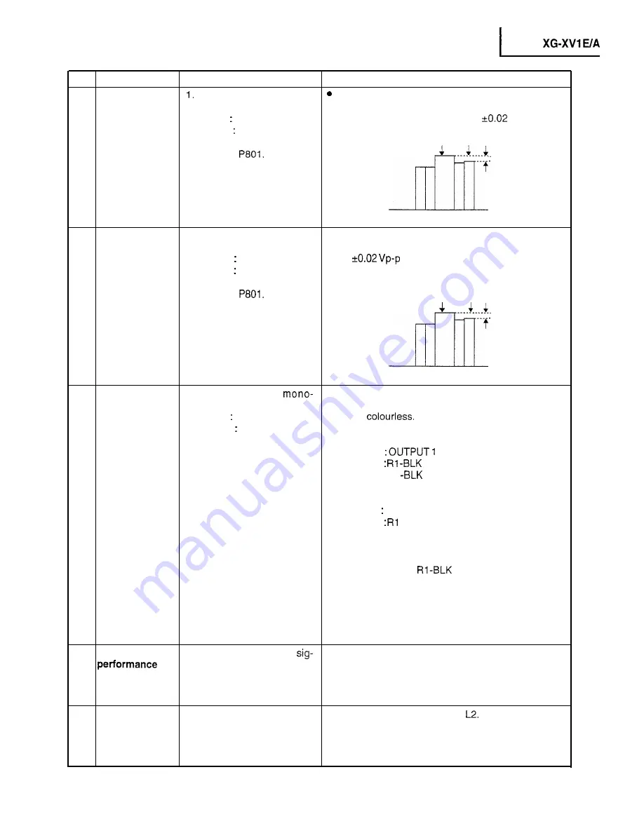
19 PAL colour

 Feed the PAL colour bar

 Using the membrane switch or the remote control

saturation level

signal.

button, adjust the difference between the 100% white

Group   VIDEO 1

portion and the red portion to 0.1 

 Vp-p.

Subject   P-COLOR

2. Connect the oscilloscope to

100% White Red

pin (1) of 


20 SECAM colour

1. Feed the SECAM colour

Using the membrane switch or the remote control

saturation level

bar signal.

button, adjust the data to have a level difference of

Group

 VIDEO 1

0.1 


 between the 100% white portion and

Subject   S-COLOR

the red portion.

2. Connect the oscilloscope to

pin (1) of 

100% White Red

21 Video white

balance

1. Feed the NTSC 

Choose the subjects Rl-GAIN and Bl-GAIN, and

scope pattern signal

make adjustment so that the entire screen looks

Group   VIDEO 2

evenly 

Subject   RI-GAIN

If the black side is not properly adjusted, first readjust

Bl -GAIN

the black side by making the following choice:

Group 


Subject   


Bl 

Then, make the following choice:

Group   VIDEO 2
Subject   

 -GAIN

Bl -GAIN

Readjust the related data.

Since the subjects 

 and Bl-BLK are common

for the RGB input and VIDEO input, feed the RGB
signal again to adjust the white balance.

22 Colour system

check

1. Receive the colour bar 

In the process mode, select Ll . Check the colour and

nal.

tint.

23 Video system

performance
check

1. Receive the monoscope

In the process mode, select 

 Check the picture,

pattern signal.

brightness and sharpness.

2 5

Summary of Contents for XG-XVI E/A

Page 1: ...RICAL ADJUSTMENT 21 TROUBLESHOOTING TABLE 29 l CHASSIS LAYOUT 89 l BLOCK DIAGRAM 91 OVERALL WIRING DIAGRAM 95 DESCRIPTION OF SCHEMATIC DIAGRAM 97 l WAVEFORMS 98 l SCHEMATIC DIAGRAM 99 l PRINTED WIRING BOARD ASSEMBLIES 145 PARTS LIST n ELECTRICAL PARTS 157 HCABINET AND MECHANICAL PARTS 195 aACCESSORIES PARTS 202 n PACKING PARTS 202 l PACKING OF THE SET 203 Seite l TECHNISCHE DATEN 45 HINWEISE FUR D...

Page 2: ...O 0 5 Vrms more than 22 kR stereo Horizontal sync signal TTL level positive negative or composite sync Q We only Vertical sync signal Same as above g pin D sub male connector for controlling personal computer g pin D sub female connector for wireless mouse g pin mini DIN connector for wireless mouse 3 8 cm round x 2 AC 200 V 240 V 60150 Hz 535 w 5 C to 40 C 20 C to 6O C Plastic 40 kHz Wave length ...

Page 3: ...The medium pressure lamp involves a risk of explosion Be sure to follow installation instructions described below and handle the lamp with care q Lamp Replacement Note Since the lamp reaches a very high temperature during units operation replacement of the lamp should be done at least one hour after the power has been turned off to allow the lamp to cool off Installing the new lamp make sure not t...

Page 4: ...ugging the cord back in This will return the projector to its normal mode OPERATION PANEL ON SIDE OF PROJECTOR RI ACK 1 MENU ENTER A lNPl T LENS SCREEN MUTE VOLUME SELECT I I MENU ADJUSTMENT button 41 WA buttons ENTER button LENS button IvlUTE button INPUT SELECT button SIDE AND REAR VIEW Note for XG XV1 A as well as Australian and NewZealand versions of XG XV1 E COMPOSITE VIDEO INPUT 1 Video BNC ...

Page 5: ...switch on the remote control is left on for more than 10 minutes without operation the power will automatically turn off To turn the power back on press any button on the remote control for at least one second VOLUME UP DOWN buttons LASER POINTER MENU button t MOUSE ADJUSTMENT 4 b v A buttons MAIN POWER switch of remote control Note Whentransportingthe remote control turn off the MAIN POWER switch...

Page 6: ... for the laser beam Always use the laser pointer at temperatures between 5 C and 4O C Inserting the Batteries Remove the battery cover as shown and insert four AA size batteries making sure their polarities match the and marks inside the battery compartment Notes Incorrect use of batteries may cause them to leak or burst l Insert the batteries with the and polarities as indicated l Remove the batt...

Page 7: ...t to Send Clear to Send Ring Indicator II0 Input Input output output output output Input Input Reference Connected to internal circuit Connected to internal circuit Connected to internal circuit Connected to internal circuit Connected to internal circuit Not connected Connected to internal circuit Connected to internal circuit Connected to internal circuit Mouse Input Terminal for NEC PC98 series ...

Page 8: ... XG XVlUA Dimensions Rear View Top View Side View I 355 I I I165 5 Lensextended 176 8 Lens housed ens at upper shift I Bottom View 8 Front View Units mm ...

Page 9: ...l out the lamp cage unit Notes l Before the replacement turn off the projector s power button make sure the cooling fan comes to a complete stop and unplug the power cord l The lamp may be still very hot Turn off the power button unplug the power cord and wait for at least 1 hour before staring the job l In fitting the lamp cage unit back into position make sure the connector is at the top positio...

Page 10: ...of the top cabinet to unhook the front cabinet Detach the front cabinet 2 3 Disconnect the remote control connector infrared R C Receiver Unit 3 Removing the top and rear cabinets 3 1 Remove the five screws from the top and bottom of the rear cabinet 3 2 Disconnect the speaker connector 3 3 Slide back the top cabinet to separate the top and rear cabinets Top Cabinet ...

Page 11: ...r 4 2 Remove the twelve side screws 4 3 Remove the two screws off the side cabinet 4 4 Disconnect the video terminal cover 4 5 Disconnect the membrane switch connector 4 6 Pull down and detach the left side cabinet 4 7 Remove the two screws off the LED PWB assembly for XG XVI A as well as Australian and NewZealand versions of XG XV1 E Video Terminal Cover1 attached only when the video board unit i...

Page 12: ...ee screws off the optical mechanism assembly 5 2 Remove the two screws off the bottom cabinet 5 3 Remove the screw off the signal PWB assembly 5 4 Disconnect the connectors of the signal PWB and output PWB assemblies 5 5 Take up and away the PWB assemblies PC Terminal Unit 12 ...

Page 13: ...power supply and ballast PWBs 6 l Remove thy two screws off the AC SW Unit on the bottom cabinet 6 2 Remove th four screws off the power ballast holder located behind 6 3 Disconnectithe connectors 6 4 Take up anb away the PWBs 13 ...

Page 14: ...the lamp with new one and take the following resetting procedure Resetting the lamp operating hour counter 1 Hold down the ENTER ADJ V and ADJ buttons on the unit and turn on the main power switch located above the AC inlet 2 Now the unit is turned on and the lamp operating hour counter is reset to zero OOOH appears on the screen BLACK LENS SCREEN MUTE VOLIME INPUT SELECT i ENTER At3J V ADJ 14 ...

Page 15: ...oating B transmission I I R transmission Marking Dichroic coating RED R reflection M2 I Relay lens 1 LlrrL A Dichroic coating 1 AL deposited face Fly eye lens coating Metal halide lamp Light source The M3 mirrors and the M5 have a coating wedge for different film thickness Set up these mirrors with their markings positioned as shown above so that their coated faces and both sides be AR coating in ...

Page 16: ...the lock screws b and c and insert the eccentric screwdriver into the notch and hole b or c Turn the screwdriver until the right and left halves on the screen get into focus First get the right and left halves in balance Then improve the accuracy while making the adjustment 2 below 1 2 Top center bottom focus adjustment 9X and Z directions Loosen the lock screws a and 7 and insert the eccentric sc...

Page 17: ...chanism This is because the dichroic prism is used for image formation When the LCD panels all get into the best focus the images are almost completely converged Convergence and Focus Adjustments TOP VIEW R LCD Mechanism SIDE VIEW G LCD panel mounting screws G adjusting plate Lock screws c SIDE VIEW Eccentric cam Y direction adjustment Eccentric cam X direction adjustment Eccentric cam 6Z directio...

Page 18: ...tric cam adjusting wrench d Hex wrench Convergence Y direction l mm Eccentnc cam Eccentric cam adjusting wrench d Hex wrench BZ direction k2 Eccentric cam Eccentric cam adiustinq wrench d Hex wrench colours Eccentric screwdriver Focus G colour Focus Z direction 0 5mm BX direction r2 Same as for R and B colours BY direction 2 Focus Adjustments the Other Way i Lock screw 1 Position Related direction...

Page 19: ...r with the LCD panel 4 Separate the LCD panel from the adjusting plate 5 Mount a new LCD panel in the reverse order of the above steps l 2 3 and 4 Readjust the convergence and focus Note that the G LCD panel needs no convergence adjustment and has a small adjustment range in the Z direction TOP VIEW FRONT 7 Lock screws c G adjusting plate G LCD EI It d G LCD SIDE VIEW 3 Lock screws 7 R B adjusting...

Page 20: ... procedure PC I F Unit CPCL0023CEOl 1 Feed the XGA pattern signal from the signal generator 2 Using the tester measure the voltage at each test point on the PC I F PWB Tester d PC I F PWB Projector XGA pattern signal input Signal generator 20 ...

Page 21: ...oscope to subjects G D and f B D respectively TPl 4 Make the following choice Group A D Subject R D XG XVI E A Hook up a signal generator or a DOSV or Mac personal computer to the projector in order to feed the signals specified in the Adjusting conditions Note All the adjusted data will be cleared by making the FACTORY SETTING 1 or FACTORY SETTING 2 Before using the previous data for adjustment w...

Page 22: ...litude Subject R2 BLK R the remote control button R2 GAIN l Next choose the subject R2 GAIN and adjust the sig For green choose the sub nal amplitude to 3 3 kO 1 Vp p jects G2 BLK a n d G2 GAIN For black choose the sub 3 3vp p jects B2 BLK and B2 GAIN 2 Connect the oscilloscope to l r 1 ______ _____ __ pin 6 TPllO2 of SC1 101 for red 1 _ _ __ _ _ _ __ Pin 6 TP1202 of f SC1 201 for green Pin 6 TP13...

Page 23: ...owering it Subject Gl GAIN again 10 RGB white balance 1 Feed the XGA gray scale l Choose the subjects Rl BLK and Bl BLK and adjust signal the black balance of the gradation Choose the sub Group OUTPUT 1 jects Rl GAIN and Bl GAIN and adjust the gray to Subject Rl BLK while balance so that the entire screen looks colour Rl GAIN R i less Bl BLK Bl GAIN B 11 NTSC 4fsc 1 Choose the group VIDEO 1 l Turn...

Page 24: ... the NTSC black sig l Using the membrane switch or the remote control nal button decrease 2 points from the level where the Group VIDEO 1 black signal becomes bit less dotted Subject BRIGHT 2 Press the membrane switch or the remote control s mute button to set the gamma correction to the process setting 17 Tint 1 Feed the NTSC colour bar l Using the membrane switch or the remote control signal but...

Page 25: ...01 100 White Red 4 Li 7 m 21 Video white balance 1 Feed the NTSC mono l Choose the subjects Rl GAIN and Bl GAIN and scope pattern signal make adjustment so that the entire screen looks Group VIDEO 2 evenly colourless Subject RI GAIN If the black side is not properly adjusted first readjust Bl GAIN the black side by making the following choice Group OUTPUT 1 Subject Rl BLK Bl BLK Then make the foll...

Page 26: ...ode select L4 Check the picture brightness red blue clock phase horizontal posi tion and vertical position l In the process mode select OFF Make sure that the off timer starts with 5 minutes counts down each minute in 1 second and turns off the set at 0 l Adjust the lens center position for the lens center to come to the n mark on the front cabinet l When the ENTER key is pressed after choosing th...

Page 27: ... R D 128 B D 128 G D 128 4 OUTPUT2 menu OUTPUT 2 Rl BLK 128 Rl GAIN 128 Gl BLK 128 Gl GAIN 128 Bl BLK 128 Bl GAIN 128 This menu is to select the colour bar pattern display ON OFF Initial setting ON 6 VIDEO1 menu VIDEO 1 NTSC H 32 PICTURE 128 AGC 128 BRIGHT 128 TINT 128 N COLOR 128 P COLOR 128 S COLOR 128 This menu is to select the gamma setting for normal operation or for process operation Initial...

Page 28: ...enu is to select the gamma setting for usual operation or for process operation Initial setting OFF r 8 LINE menu LINE Ll L2 L3 L4 OFF TEMP OFF TEMP CHECK Lamp on time display I Initialization EEPROM I Initialization without j 1 blue background I 1 Factory setting English Factory setting 1 Japanese I I L _I r i Cyan Yellow in solid and cross hatch pattern I I Lamp 1 Step 8 l 6 I Colour bar I Chara...

Page 29: ...cted With the contrast control at maximum I I Is the voltage at TCI connector as No specified L I I I 1Yes 1 A I I I Power circuit faulty I I _ _ _ I Hook up a per sonalcomputer Does an image appear No Check the clock circuit and its peripheral circuits Check the video circuit and its Does the on screen display function r i d t 1 Does the remote control function No _ I I k h r __ em _ _ _ I I I En...

Page 30: ...al circuits I I Aretheresignalsatpins 141 145 No 148 and 159 of IC8020 Yes I m f lC8025 or its peripheral circuit faulty I t I No Is the input having a resolution below XGA level or in the video mode Yes Are there signals at pins 238 and 239 of lC8025 No Yes I __ ___ I 41 t IC8020 or its peripheral circuit faulty I _ I v Are there signals at pins 13 14 t lC8025 or its peripheral circuit faulty t m...

Page 31: ...peripheral circuit faulty t I Is there signal at pin 15 of IC8051 No _ I I Yes I _ __ __ I t IC8015 or its peripheral circuit faulty t I _ _ _ _ _ _ _ I I Check the video circuit and its t I peripheral circuits I I I Is image as specified at resolution No above XGA level Yes __ ___ r Check the XGA video circuit and its i peripheral circuits I _I Is image as specified at resolution No below XGA lev...

Page 32: ...or its peripheral circuit faulty I AretheresignalsatRllAOthru 7 NO and Rl 1 BO thru 7 of lC8025 mm _ Yes I IIC8011 or its peripheral circuit faulty I __ Are there signals at Rl2AO thru 7 and RI 2B0 thru 7 of lC8025 I I Yes I KC8020 or its peripheral circuit faulty f I I Are there signals at Rl thru 10 and No Gl thru 10 of IC8030 Yes _ I I f lC8025 or its peripheral circuit faulty I N o I _ _ I I I...

Page 33: ... IC8010 or its peripheral circuit faulty I w m Are there signals at Gl2AO thru 7 and G12BO thru 7 of lC8025 _ _ __ w I IIC8020 or its peripheral circuit faulty I Yes I e e l 41 Are there signals at Rl thru 10 and No Gl thru 10 of IC8031 __ m v Yes I I v I lC8025 or its peripheral circuit faulty I I Are there signals at the bases of Ql9 No and Q21 I I t lC8031 or its peripheral circuit faulty I I A...

Page 34: ...thru 7 of lC802 5 Yes I I IC8009 or its peripheral circuit faulty I I _ _ s e I I I IC8020 or its peripheral circuit faulty 1 I _ m v l Y e s v Are there signals at Rl thru 10 and No Gl thru 10 of lC8032 _ _ e Y 1Y e s I I 1 lC8025 or its peripheral circuit faulty I I I Are there signals at the bases of Q23 No and Q25 _ _ I I lC8032 or its peripheral circuit faulty I I I Are there signals at pins ...

Page 35: ... Checking the OSD circuit atid its peripheral circuits 1 Are there signals at pins 7 8 37 No and 38 of TC2 Yes I _ _ e y I I LCP circuitry faulty I I I Are there signals at pins 1 and 2 of No lC8037 I _ f lC8025 or its peripheral circuit faulty I I I Are there signals at pins 71 74 No thru 79 of lC8025 I Yes m y I 4 t lC8037 or its peripheral circuit faulty I I _ _ I I f lC8036 or its peripheral c...

Page 36: ...____1 i tRGB bnal output circuit t t their peripheral circuits as I 1 I we l as switchingcircuit L s mm 1 I Checking the video unit circuit I Is there video signal output at pin 7 No of IC6001 I _ Yes I I Check the IC6001 selector switch t terminal v oltage and input circuit No I Is there video signal input at IC6004 r 1 Yes I ______ I Check the low pass and buffer t I circuits of Q6009 thru Q6014...

Page 37: ...L and SECAM I Check the level of 5pin switch of f f IC403 and its peripheral parts t I Check the buffer circuit of Q428 thru t Q430 and its peripheral circuits f _ _ _ _ I Checking IC801 RGB signal output circuit Are there RGB output waveforms at No pins 31 32 and 33 of IC801 t Go to No colour or unusual tone f No Y signal or Out of sync I I l performance at pins 17 and 18 of l Are A D outputs of ...

Page 38: ...t i I Are there output waveforms at pins 3 chroma signal and 6 Y No signal of IC816 Yes I I f Go to Checking IC801 RGB signal t f output circuit I _I Checking IC806 3 D noise reduction circuit and its peripheral circuits Are there signal inputs at pins 4O Y signal and 45 chroma signal of No IC806 Are there signal outputs at pins 55 Y Are there signal outputs at the ___ _ t Check IC816 and IC801 RG...

Page 39: ...ut at pin 20 of IC802 No 1Y e s f Go back to the signal processing I block i Are there signal outputs at pins No L I 1 l R Y and 12 B Y of IC802 Yes I ___ _ I Check the X802 oscillation IC802 1 f and their peripheral circuits I I __ I I Check IC803 IC804 and their t I peripheral circuits I _ _ I No or unusual Y signal I Is there Y signal input at pin 21 of No IC8017 Yes Go back to the signal proce...

Page 40: ...__ ____ Check the pulse shapinq circuit of t t IC601 IC6b2 and IC603 I I ______ _ _ _ _ _ I Check PC604 and its Deripheral I circuits and go to Checking the clock i circuit and its peripheral circuits ____ I No or unusual vertical sync Is there vertical sync pulse output at No pin 4 of IC801 Yes I _ I Check IC801 and its peripheral t circuits I I _ I t Check IC604 and its peripheral I circuits and...

Page 41: ...o Checking the through 1 I output circuit Go to Checking the remote f control circuit I _ _ _ 1 I II l Is specified cable connected No between PC and projector Yes r _ w I I I Use specified cable I I I No Is supply voltage as specified Yes r q I I Power circuit in trouble I v I I No Does image appear r __ _ _ t Check the connectors starting t from the PC unit input circuit t I t t Go to Checking t...

Page 42: ...02 IC1202 and IC1302 I and their peripheral circuits i Are there signal outputs at pins 231 25 271 34 35 and 37 of IClllO ICllll No lCl210 IC1211 ICl310 and ICl311 Yes Check the input and output I r signals at IC1106 ICl206 and t 1 ICl306 Check also IClllO ICllll IC1210 IC1211 I t IC1310 IC1311 and their t penpheral circuits I v _ _ J No Are there signal inputs at SC1 101 SC1201 and SC1301 NO __ I...

Page 43: ...nd 2 of P1403 Yes v Check the amplifier of IC301 and IC302 and their peripheral circuits I the IC303 control voltage the Pi 501 I connectors etc Are there audio signal outputs at pins NO 4 and 6 of IC7301 Yes I t Check lC7301 and its peripheral I I circuits t I __ I I ___ I m q t If the voltage at pin 7 of IC7301 is not as specified check Q5501 I t Check lC7301 and its peripheral t t t t Q5502 and...

Page 44: ...and EC I _ __ connectors for short circuit or Yes i voltage drop __ J I _ ___ I Q1707 or PC1702 defective 1 Replace it e m Is voltage of over IV supplied to Beplace the sub PWB or check its I Internal elements ___ J I Checking the throughout circuit I I Is analog output coming from PC No 1 I j Digital output not acceptable T _I Are LCP and monitor interconnected No with an appropriate cable I Yes ...

Reviews: