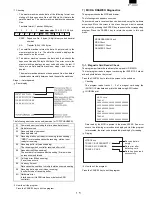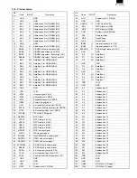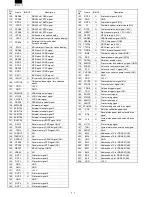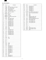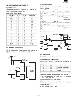
7)-2. Drawer 1 Check
Checking
The program turns on the drawer 1 solenoid, senses the value of the
drawer open sensor every 100 ms, and displays the operating status.
Display
How to exit the program
Press the CANCEL key to exit the program.
7)-3. Drawer 2 Check
Checking
The program turns on the drawer 2 solenoid, senses the value of the
drawer to open the sensor every 100ms, and displays the operating
status. The procedure for displaying the menu and exiting the pro-
gram are the same as for the drawer 1 check.
8) Dot Pulse Adjustment:
R/J printer dot pulse width adjustment
The dot pulse width adjust circuit is provided to control the width of
the current applied to the dot head of the printer, according to a
supply voltage fluctuation.
When the circuit is changed by repair work, the dot pulse width needs
to be adjusted using the 200k pot VR2.
Display
How to exit the program.
Press the CANCEL key to exit the program.
Open Sensor : OPEN (or CLOSE)
DRAWER 1 Check
Dot pulse adjustment
+24V
+24V
VCC
TRG
D1
1SS355
D2
E102
R135
2K
R81
130K"F"
VR2
200K
ZD5
UDZ4.3B
5
6
7
8
4
IC10B
BA10393F
Q5
KRC106S
C59
10000pF
R263
10K
VCC
+24V
VCC
PE
TP
R136
62K
R137
3.3K
410
370
330
420
410
400
390
380
370
360
350
340
330
320
22
21.6
23
24
25
26 26.4
Transmission width (µs)
Drive voltage (V)
±3µs
(Allowance)
Pd
Pw
Pt
TRG
PE
Pw
Pt
4µsec
1000µsec
Pd is adjusted to 373±3µsec. when Vp is +24.0V.
Summary of Contents for UP-600
Page 8: ......
Page 77: ...CHAPTER 9 PWB LAYOUT 1 MAIN PWB 1 A side R VRD RC2EY103J is added IC1 94pin R71 ...
Page 78: ...2 B side Symbol PartsCod ...
Page 79: ...2 CKDC PWB 3 DISPLY MCR PWB 1 A side 2 B side 4 RS232 RELAY PWB 1 A side 2 B side ...
Page 80: ...5 IPL ROM PWB 1 A side 8 POP UP DISPLY 9 LCD I F PWB 2 B side 6 TCP IP RELAY PWB 7 VR PWB ...


