


E – 4
I
E
F
0
2
1
3
4
5
5
9
D
C
B
G
H
6
780 A
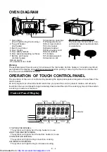
OVEN DIAGRAM
1. Oven lam p
(It w ill light during the cooking.)
2. Top grill heater
(top heater)
3. See through door
4. Door hinges
5. Door safety latches
6. Door seals and sealing surfaces
7. Bottom grill heater
(bottom heater)
8.Oven cavity
9.Turntable m otor shaft
M etal racks——High and low
The racks are for Grill, M ix, Con-
vection and recom m end autom at-
ic operations.
10.Ventilation openings
11.Waveguide cover
12.Door open button
13.Control panel
14.Digital readout
15.Pow er supply cord
16.Outer cabinet
17.Turntable
18.Turntable support
19.Ventilation slit
OPERATION OF TOUCH CONTROL PANEL
The operation of the oven is controlled by pressing the appropriate pads arranged on the surface of the
control panel.
An entry signal tone should be heard each tim e you press the control panel to m ake a correct entry.
In addition the oven w ill beep for approxim ately 2 seconds at the end of the cooking cycle, or 4 tim es w hen
a cooking procedure is required.
Control Panel Display
Warning:
The accessories w ill becom e very hot w henever the top heater, bottom heater or convection sym bols
are lighted in the display, and use thick oven gloves w hen putting / rem oving the food or turntable into/
from the oven to PREVENT BURNS.
1. TOP HEATER SYM BOL
The sym bol w ill light w hen the top heater is in use.
2. BOTTOM HEATER SYM BOL
The sym bol w ill light w hen the bottom heater is in use.
3. CONVECTION SYM BOL
The sym bol w ill light during convection cooking.
4. M ICROWAVE SYM BOL
The sym bol w ill light during m icrow ave cooking.
1
2
3
4
Indicator
http://www.usersmanualguide.com/