background image

Copyright 

©

All rights reserved, SHARP CORPORATION

Confidential

71

5.5.Installation tool 2

Product Name (temporary)

Purpose and Precautions for Use

Image

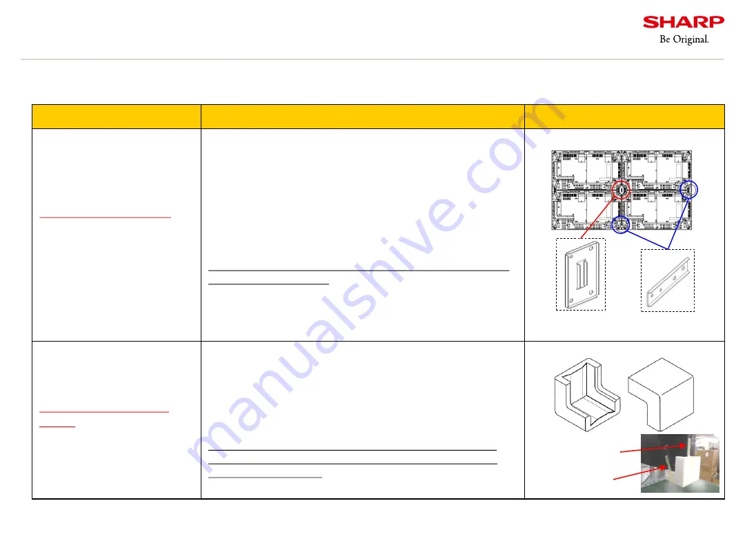
Screen alignment tool 

Plate A (UKOG-1025MPZZ)

Screen alignment tool 

Plate B (UKOG-1026MPZZ)

*Tool for this model only

Screws 

M6X10)

(XBPS760P10KS0

Plate A 2 screws

Plate B  4 screws

*Not inessential.  M6 
screws with length of 8 to 
10mm can be used.

Adjusting differences in level (thickness) in video wall

- Requires four M6 x 8mm screws for four displays. 

Requires two M6 x 8mm screws for two displays.

- Use washer or spacer between displays as necessary.

- When using this tool, you need a space to go around to the 
back of the display.

- Make sure the level difference is 

below 3mm 

before using 

this tool.

*Extreme twist to this product may cause crack of the panel, 
light leakage or failures.

Corner Protector

(UKOG-1008MPZZ)

*Common tool for PN-V 
Series

Reduce shock while moving and installing

- Protect display from impact by covering the both lower 
corner of a display.

- Requires two pieces for one display.

- This tool can increase installation efficiency. Use it as 
necessary.

*This tool can not be attached to the display with magnet. 
Use a sticker. (Attach a sticker to the handle part and  the 
side of the rear cover.)

Note: Contact the dealer from which you purchased the main unit or our sales reps if you need above tools.

(UKOG-1025MPZZ)

(UKOG-1026MPZZ)

Handle part

Side of rear cover

We provide the following service parts for installation (for a fee).

Summary of Contents for PN-V701

Page 1: ...Information Display Installation Guidelines PN V701 Sharp Corporation Business Solutions BU Visual Solutions Business Unit October 28th 2019 Normal Version Ver 1 2 ...

Page 2: ...tion P36 38 Handling this material This document is to explain how to design and install large displays for our business partners Please do not distribute this document or its contents to other companies or use it in products of other companies Please note that value and expressions on this document are subject to change without notice 3 9 Precautions for mounting on the wall P39 40 3 10 Rotate di...

Page 3: ...Copyright All rights reserved SHARP CORPORATION Confidential 2 1 Overall precautions ...

Page 4: ...ow to hold the display holding positions How to temporarily store the display after taking it from the box We recommend storing the display temporarily on a temporary stand How to check and or store the accessories of display 4 Install a stand and wall mounting brackets This model requires close attention to handling due to its thin bezel Even dealers or workers familiar with the conventional mode...

Page 5: ... moving the display be sure to hold it with the carrying handles Do not hold any other parts LCD surface Precautions in Handling Don t touch the surface of LCD screen Do not grab impact or apply pressure to the top bottom left and right of the frame 1 1 Procedures of installation Please thoroughly observe these recommendations 2 ...

Page 6: ...yed at the upper left of screen 2 Press the buttons 3 The screen display changes in the following sequence each time you press the button Black Dark Blue Dark Green Dark Red Blue Green Red White Gray1 Gray2 4 Turn off the power after checking the display 1 Press the MENU and INPUT keys over 5 sec and F is displayed at the upper left of screen 2 Press the buttons 3 The screen display changes in the...

Page 7: ...fety equipment etc We will not take any responsibility for any failure damage loss etc which arise from particular installation high ceiling mounting etc and or installation by other companies than Sharp Prior to the installation examine the potential problems caused by the installation location and installation method and operate within the appropriate environment In case of product failures rega...

Page 8: ...Copyright All rights reserved SHARP CORPORATION Confidential 7 2 Design precautions ...

Page 9: ...he heat gets trapped in the display the temperature will rise the brightness of back light will be lowered and the LCD screen will be darkened When the temperature inside gets too high the power will be turned off and the display will go into the standby mode Temperature Heat on LCD surface When the temperature on the surface of the LCD screen is too high it will break down or uniformity issue wil...

Page 10: ...ontrolled depending on the configurations of video wall and clearance space at the back Temperature of LCD surface Under 60 Follow the requirements above when installing video wall display Refer to the countermeasures and follow the installation conditions when installing video wall Follow the installation conditions for peripheral devices as well Secure the space at the top bottom left right fron...

Page 11: ...cape video wall Unit degree Celsius Clearance space at the back side 3 5cm or more 10 0cm or more 20 0cm or more 30 0cm or more 40 0cm or more 50 0cm or more 70 0cm or more 37 5 or less 38 0 or less 38 5 or less 39 0 or less 39 0 or less 39 5 or less 40 0 or less 1 x 3 portrait video wall Unit degree Celsius Clearance space at the back side 3 5cm or more 10 0cm or more 20 0cm or more 30 0cm or mor...

Page 12: ...ding temperature to be around 0 to 40 Add a cooling fan Widen the ventilation space Using an air conditioner or a fan Lower the brightness of display The effectiveness of each countermeasure differs depending on the installation environment Choose the best measure for respective environment Countermeasures for the lack of clearance space Fan installation Heat prevention unit Apiste co 2 1 Precauti...

Page 13: ... outdoor Set a sun shade above the display Utilize the shade of the building Install the display in a place without direct sunlight Change the direction of the display to avoid sunlight Utilize trees or some objects blocking out the direct sunlight Be careful about strong wind like hurricanes Effect If being used under direct sunlight The LCD screen would look much darker than usual LCD would be d...

Page 14: ...using anti dust display When using a display casing mount an anti dust air filter Precautions for Anti dust air filter Double filter makes its life longer by replacing the finer screen pre filter A filter increases the air resistance It may raise the internal temperature of the casing Reduce the air resistance by using larger filter The following points should be taken care of in designing the cas...

Page 15: ...ARP CORPORATION Confidential 14 DO NOT cover the fan cover area for replacing the fan 2 4 Position of fan Fan cover is attached firmly with screws 303 21 Cover removal Do NOT cover this area for replacing of cooling fan 172 172 54 45 ...

Page 16: ... screen protector for your purposes Generally when decreasing glare image quality comes down Select the suitable protection panel in each installing site The closer a distance from the protection panel to the LCD panel is the more clear image you can get but temperature on the LCD surface rises if it s too close Secure space of 3cm at least between protective panel or glass and the LCD surface to ...

Page 17: ...of the vents of radiators Near the sea or lakes where there is high humidity The environment which has high possibility of liquid drops Semi outdoor where strong winded rain typhoon could potentially reach the display Below the pipes in the ceiling when the pipes have leaking problems drops of water may enter the display through the vents When you install in these places take some countermeasures ...

Page 18: ...e protection panel be aware of expansion due to heat or moisture absorption Acrylic protection panel can expand about 0 4 approx 6 2 mm 70 Install the protection panel with a space so that it won t be distorted due to expansion Expansion The followings are expected to prevent afterglow Display video as long as possible e g display 10 seconds video after 5 minutes still image Prevent increase of th...

Page 19: ... by delaying the wake up time using power on delay function Movable Blade Plug Normal Blade Type No bushed Bushed Power Strip Confirm the rated current value of the power strip The total amount of current consumption of all the connected devices shouldn t exceed the rated current value Avoid using a movable blade plug which may be damaged if excess force is applied to It may also cause abnormal he...

Page 20: ...on e g HDMI DVI or DisplayPort connection for high quality images When you use light conversion cable to extend the transmission distance EDID may not be read accurately Not reading EDID accurately displays cannot display correctly Check the image quality beforehand when using these devices Cable When you use media devices e g personal computer DVD player or peripheral equipment e g distributor vi...

Page 21: ... HDMI 1 4 DisplayPort 1 3 This terminal allows the daisy chain connection of up to 25 displays by connecting the displays to each other through the Display Port input terminal If the number of daisy chained displays exceeds the maximum limitation number video might not be displayed properly HDCP encrypted video signals up to 4 displays The first display is D SUB COMPONENT up to 4 displays The firs...

Page 22: ...d for adjustment in installation considering display allowance long sides 1 5 mm short sides 1 0 mm and thermal expansion 2 11 Precautions for space between displays Dimensions Weight Approx 37 0kg Four holes for installation tools Fan cover VESA holes x 4 Handles User holes for PN ZR02 Stickers are attached to conceal the holes in a new display Outer Dimension Discontinued from production in Janu...

Page 23: ... the brightness of display Power consumption and heat will be suppressed 3 Secure a plenty of space at the front back of the displays 4 Provide ventilation between displays It is effective to use the spot cooler or fan in the back Note Dust can be easily attached to displays by wind Thermal influence Secure enough space considering thermal expansion The minimum space can be calculated as follows S...

Page 24: ...ays Attach the blind tape on the rear Keep the display ambient temperature in the range of 0 to 40 Secure the appropriate space on front back above below right left of the video wall 2 11 Precautions for adjacent installation Case Study Secure a space at the bottom of the displays to intake cold air Add a fan to release the hot air ...

Page 25: ... Vertical orientation is the most recommended The inclination angle is limited within 0 to 20 degrees upward downward Consult us beforehand when installing the display in the inclined orientation even under 20 degrees Vertical orientation is most recommended Do not incline over 20 degrees Over 20 Under 20 Over 20 Under 20 ...

Page 26: ...Copyright All rights reserved SHARP CORPORATION Confidential 25 3 Installation precautions ...

Page 27: ...RPORATION Confidential 26 3 1 Major failure modes due to mishandling Broken panel Line defect Light leakage due to deformation of a bezel Blurred Not display when a power switch is turned on Belt shaped defect SHARP SHARP Display abnormally ...

Page 28: ...r Do not carry the display in vertical orientation even temporally Carry it in horizontal orientation Consult with us BU beforehand when using a special case Do not reuse the packaging materials Packing size Carry the display with a wheeled cart with 2 or more people Do not carry the display in vertical orientation Wide mm Length mm Thickness mm Weight kg approx 1 865 1 100 375 57 0 ...

Page 29: ...RP CORPORATION Confidential 28 3 3 Prohibitions in storage and transfer in a packaged form DO NOT STACK DO NOT STEP DO NOT DROP DO NOT APPLY SHOCK DO NOT OVERTURN DO NOT PUT IN PORTRAIT ORIENTATION DO NOT STORE ON SLOPE DO NOT TOP LOAD ...

Page 30: ... materials reattached to protect displays from flaws in installation Check the operation and the display Reattach the protective film and corner protective materials 1 Open the package 2 Remove the protective film and corner protective materials OK Note Keep the packing materials till the completion of installation NG 3 Check the operation and the display 4 Reattach the protective film and corner ...

Page 31: ...hed at the bottom of the box Lift up the box to take out the display 3 5 Precautions for unpacking Unpacking Remove 4 joints attached on the bottom of the box and lift up the box Hold the inner tabs of the joint from the both sides and remove it downwards LCD Remove the packages on the top of the product and take the product out of the bag ...

Page 32: ... the bezel e g by bending pulling It may cause damage failures CAUTION DO NOT grab impact or apply pressure to the top bottom left right front rear of the frame This may cause injury or malfunction CAUTION DO NOT load another display on the top of the bezel of a display This may cause product damage and failures Protective film Remove the protective film just before the final installation When rem...

Page 33: ...he display when lifting up a display lying on the floor Support the display symmetrically by holding the both handles on the both sides of the display to provide equal pressure on the display Use handles in the symmetrical positions 3 DO NOT apply pressure on the edge or corners of the LCD screen side Failures may be caused by lifting up the display lying on the floor by using the edge of the LCD ...

Page 34: ...not to store and keep the display itself or packaged display in inclined state Be sure to preserve and keep it on the horizontal level Do not store and keep the display itself or packaged display in inclined state 2 Remove the protective film slowly toward the LCD screen side so that the bezel parts won t come off NG OK ...

Page 35: ... strongly recommend that corner protective materials are attached until just before combining displays finally However it won t guarantee against failures Protective Film Corner Protective Materials Remain the corner protective materials attached until just before the final step of combining displays Completion of installation Corner Protective Materials 3 6 Precautions in installing and handling ...

Page 36: ...w in diameter Too large hole may cause the installed display to fall out Use the appropriate length of screws stipulated in the operation manual Too long screw may cause the installed display to fall out Prevent screws from loosening e g by using screws with washer Screw torques tight with 3N m or below Tightening torque 3N m 使用するネジ長さは ディスプレイの 取扱説明書を確認してください 固定用ネジ M6 取付金具 ディスプレイ 背面キャビネット 固定ボス Hole...

Page 37: ...plays to the stand after it is confirmed that replacing fan cover is detachable 3 8 Precautions on stand installation 1 Surrounding space Securing space at upper above Secure space above the display to exhaust the heated air Secure space of 20cm above the display so that displays can be lifted up in detaching Secure space at the surface and lower areas as well referring to Precautions for temperat...

Page 38: ...cautions on stand installation 2 Do not install with a stand for the purpose of carrying displays It may cause failures due to the vibration or collision between displays The floor stand with caster offered by CHIEF is recommended It is designed for adjusting the installation location Do not install it for the purpose of carrying displays Do not combine stands to install displays It may cause fail...

Page 39: ...tial 38 3 8 Precautions on stand installation 3 Collision between displays Do not make displays collide with each other Do not make cables be caught between displays Collision with metal fittings Do not make displays collide with metal fittings Cable caught ...

Page 40: ...the cooling fans If the space is small the upper displays absorb heat exhausted from the lower displays and the temperature inside may increase Refer to Precautions for temperature and clearance space for detailed information Use the mounting bracket which can support 4 times the weight of the display The wall or concrete wall concrete pillar etc must support 4 times the total weight of displays a...

Page 41: ...pply the load on the top of the bezel by leaning against displays in wiring Use the pulling wire when you want to put in displays Do not push displays directly Pantograph type metal fittings When you use pantograph type metal fittings put them in out slowly so that displays won t collide with each other Pantograph type metal fittings Pulling wire ...

Page 42: ...confirming the UP label Never mount upside down In portrait orientation change the THERMAL SENSOR SETTING of OSD to PORTRAIT If the setting remains landscape in portrait orientation the temperature sensor does not work properly This Side Up Label 3 10 Rotate direction for portrait mounting Front Front MENU MONITOR ROTATE 180 ON 1 2 3 1 2 3 When video is displayed upside down in portrait orientatio...

Page 43: ...or professionals such as broadcasting stations It looks that the image is cut between the upper and the lower displays when the bar is moved Progressive Scan The image looks to be bent but there is no image gap between the displays It is not noticed unless the image is in portrait orientation You need to set PICTURE FLIP to ON or prepare a scan converter as the image is turned upside down in the i...

Page 44: ...on than in vertical installation 3 Replacement of fan is recommended every 5 years which is same as in vertical installation Note The operation manual bundled with the main unit does not describe the explanation about the horizontal installation It is just a guide and it shall not warrant the product life The actual product life may vary depending on the operating environment such as hours of use ...

Page 45: ...4 Turn off the power after confirming the display When using key on the rear panel 1 Press the MENU button and the INPUT button at the same time until F is displayed on the top left of the screen display When F is displayed press the MENU button 2 Press the button 3 Press the button left of the POWER button viewed from the front and change from VERTICAL to FACE UP 4 Turn off the power after confir...

Page 46: ...l may be transformed or curved inward by heat depending on its material Consider the flexure of protection panel load from upper part installation method and the material of protection panel in installation Secure space between the display and the protection panel of more than 10cm Make sure that the protection panel won t touch the LCD surface even if it is curved Do not apply a load on the LCD s...

Page 47: ...pace Based on the temperature actually measured estimate the temperature of each part during the condition that the room temperature is the highest and take necessary countermeasures against heat For instance it is effective to install a ventilation fan to reduce overheating We recommend using a wireless mouse and keyboard to secure the PC operability 3 13 Precautions on PC installation Considerat...

Page 48: ...rush when dust attaches to the LCD surface Do not wipe with a damp cloth dusty cloth and chemical wiping cloth 3 14 Maintenance Checking Items Maintenance Checking Items Daily maintenance Clean LCD surface Monitor operating conditions Regular maintenance Check the installation conditions e g rattling main unit loose fixing brackets and screws etc Replace the fan Check and replace the black tape to...

Page 49: ...he product life Contact the dealer reseller from which you purchased the main unit or our sales reps for the information of replacement parts Replacement of Fan In addition to the regular maintenance we recommend the Maintenance Contract of SHARP Business Solution Contact the dealer from which you purchased the main unit or our sales reps for the information ...

Page 50: ...Copyright All rights reserved SHARP CORPORATION Confidential 49 4 Color adjustment ...

Page 51: ...rightness between displays if you can acquire measurement data before installation Contact our sales reps for the information about acquiring the measurement data if you have the product number You may also get it from the main unit directly by DITwC Installation Complete Fine color adjustment with DITwC 4 Is further adjustment required Unpack display power check Auto color adjustment with DITwC 2...

Page 52: ...deo wall layout by DITwC 1 1 Acquiring Measurement Data Procedure for Layout 1 At the Calibration Layout RGB Contrast Adjustment Layout screen set the video wall condition e g 2 x 2 landscape 2 Select measurement results folder 3 By clicking the Simulate Recommended Layout calculations result will appear by serial no Layout Flow 2 Determination layout with DITwC Layout Result Layout Result Figure ...

Page 53: ...ess color variation between displays can be minimized by adjusting each display R G B contrast and brightness value 1 Set up network connection LAN and register each display in Monitor Control Refer to the Display Installation Tool manual for detailed information DITwC Display Installation Tool with Calibration Utility Refer to DITwC manual for further information LAN Hub Adjusts each item of MENU...

Page 54: ...rding to the purpose of use 1 SHARP Advanced Uniform Color Calibration Technology Setting 2 Using a remote control unit MENU Picture Uniformity Factory default setting Uniformity Usage Brightness Mode 1 Priority on Brightness Equivalent to 700cd Mode 2 Intermediate Equivalent to 600cd Mode 3 Priority on Uniformity Equivalent to 500cd Image of color uniformity calibration by Sharp UCCT Before Calib...

Page 55: ...but the uniformity between displays may be different especially in specific color contents such as corporate colors Then subtle color adjustment may be required You can adjust it easily with this software DITwC Display Installation Tool with Calibration Utility Refer to DITwC manual for further information RGB Contrast Adjustment Hue and Saturation Adjustment PN V701 limited ...

Page 56: ...ring devices Recommended models 1 Contact type Datacolor Spyder3Pro 2 Spyder4Pro Spyder5Pro X rite ColorMunki Photo Design 2 Not compatible with Windows 8 8 1 10 2 Non contact type 3 FLIR Integrated Imaging Solutions Inc Blackfly GigE PoE BFLY PGE 05S2C CS 3 When measuring and adjusting one display use the contact type not the non contact one USB LAN cable 4 A measuring device 1 Contact type A mea...

Page 57: ... PN V701 4 7 Color adjusting after calibration 6 1 DITwC stands for Display Installation Tool with Calibration Utility which is a Sharp s dedicated application 2 It can not be adjusted in a non contact type measurement 3 It can be adjusted in both contact type and non contact type measurements Refer to the instruction manual of DIT DITwC for details The white balance of a measured display can be a...

Page 58: ...red Calibration with measurement data by separately sold sensors is also available Sharp provides this software Use Screen Image V Series2 Display Installation Tool Note This software can be used with same as PN V701 V550A It can not be used with PN V60X series Control PN V701 from PC Turn power on off switch input signal change settings etc Control multiple information displays Backup and restore...

Page 59: ...reserved SHARP CORPORATION Confidential 58 Use Figure Image Display Management Tool Monitoring the operational status of display scheduling mail setting and security setting Sharp provides this software 4 8 Software Tool 2 ...

Page 60: ...y built in pattern in IDP and adjust color and brightness Yes Yes Caribration Measurement data aquirement Acquire factory measurement data from IDP Yes Recommended Layout Layout recommendation from multi measurement result Yes Recommended Settings Adjust RGB contrast value and brightness value from multi measurement result Yes Calibration with measuring devices Measure the screen by optional measu...

Page 61: ... Calibration Display Management Tool Register Monitor DIT DITwC Monitor Control DMT Register edit individual IDP and Groups Yes Yes Yes Password Password operate authority setting Yes Monitoring Check status of each IDP Yes Schedule Schedule setting for power on IDP Yes Mail Monitoring settings Mail and monitoring setting Yes 4 9 Software function comparison 2 ...

Page 62: ...Copyright All rights reserved SHARP CORPORATION Confidential 61 5 Optional tool and installation tool ...

Page 63: ...mm 45kg LBM3X1UP 2 4 CHIEF 1 688mm x 244mm x 1 727mm 44kg Wall mounted fittings Pantograph type 5 with tilting height depth adjustment Landscape LVS1U CHIEF 903mm x 101 348mm x 485mm 17kg Portrait LVS1UP CHIEF 496mm x 104 351mm x 825mm 16kg Pantograph type 5 with a location adjustment function Landscape Portrait FTK WM M400B Japan F S only Japan 560mm x 119 326mm x 431mm 21kg Tilt angle adjustment...

Page 64: ...andscape LBM3X2U CHIEF 106kg Portrait x 3 displays Anchor fixing type Portrait LBM2X2U CHIEF 81kg LBM3X1UP CHIEF Landscape x 4 displays Caster type 75kg Wall mounted fittings Drawing Type with tilting height depth adjustment Landscape LVS1U CHIEF 1 020mm x 560mm x 100mm 20kg Portrait LVS1UP CHIEF 890mm x 710mm x 100mm 19kg Drawing Type with a location adjustment function Landscape Portrait FTK WM ...

Page 65: ...all displays in daisy chain with RS232C cable and attach the sensor box at the top of the display Remote Control Unit Remote Control Sensor Box This model is not compatible with Remote Control Sensor Box in PN ZR01A for V55 and in PN ZR01 for V60 due to the differences in an internal substrate The old remote controller can be used Note The BRIGHT and VOL buttons to adjust brightness and volume are...

Page 66: ...HDBaseT x 1 LAN x 1 10BASE T 100BASE TX USB x 1 USB 2 0 Power Supply From display main unit Receive an HDBaseT 2 0 signal via a single STP Category 6 cable By using an economic and flexible Ethernet cable connect an HDMI device PC BD player etc to the display Transmit not only video audio USB LAN and RS 232C signals but also a USB signal over a single cable HDBaseT 2 0 compatible Long transmission...

Page 67: ...CONTROL ROUTE to OPTION in display menu When CONTROL ROUTE is set to OPTION you cannot set POWER SAVE MODE to ON 3 The communication speed is fixed to 9600 bps 4 When HDC S400 is combined the controlling function by RS 232C and LAN are not available 5 When MSD 702 and HDC S400 are combined HDMI CEC function does not work properly 6 You can connect a USB mouse or keyboard HID class 7 If using an Ex...

Page 68: ...is attached to the LAN terminal on the PN ZB03H to the network A display is also connected to the network HDMI Cat 6 or higher shielded cable PN ZB03H LAN HDBaseT Transmitter PC LAN Use Scene 2 Connect a remote PC to the network by connecting the LAN terminal on the PN ZB03H to the network A display is also connected to the network Share the network through HDBaseT Share the network through HDBase...

Page 69: ...s supports daisy chain connection you can display a video on multiple monitors by connecting displays in daisy chain You can use commercially available distribution transmitter when the display doesn t support daisy chain connection or the displays are installed far from each other Q Is it possible to display a video by using Cat 5e cable or UTP cable an unshielded cable A No We don t guarantee th...

Page 70: ...les on the top of the display enabling lifting the PN V701 up to a high location during installation It is inserted into holes on the top and the side of the display enabling lifting it up for portrait orientation Requires two pieces for one display It is the same function as UKOG 1005MPZZ This installation handle is to improve the efficiency of installation Use it as necessary Installation eyebol...

Page 71: ... All rights reserved SHARP CORPORATION Confidential 70 Attachment place of installation tool 5 5 Installation tool 1 Attachment place Installation handle Installation eyebolt Portrait install Installation handle ...

Page 72: ...around to the back of the display Make sure the level difference is below 3mm before using this tool Extreme twist to this product may cause crack of the panel light leakage or failures Corner Protector UKOG 1008MPZZ Common tool for PN V Series Reduce shock while moving and installing Protect display from impact by covering the both lower corner of a display Requires two pieces for one display Thi...

Page 73: ... After installation no need to detach the protection spacer Protection spacer for Portrait UKOG 1010MPZZ Common tool for PN V Series Installation positioning and Protection of display Insert this spacer between displays to prevent collision between displays thickness 0 5mm This tool is used to avoid damage of the bezel in installation and to adjust the position of the displays Use it as necessary ...

Page 74: ...e in level LCD Precautions Approx 204mm from the bottom on the rear side The LCD surface is on the front Approx 205mm Approx 204mm Two points of protecting spacer for horizontal bezels Two points of protecting spacer for vertical bezels Approx 146mm Approx 147mm On the service hall of the rear The LCD surface is on the front On the service hall The LCD surface is the front ...

Page 75: ...ily to check operation and perform settings before installation Requires two pieces for one display Requires two M4 screws for each stand This tool helps increase installation efficiency Use it as necessary The conventional pipe type stand will be change to this type Both compatible Note Contact the dealer from which you purchased the main unit or our sales reps if you need above tools We provide ...

Page 76: ......

Reviews: