background image

8

E

8

E

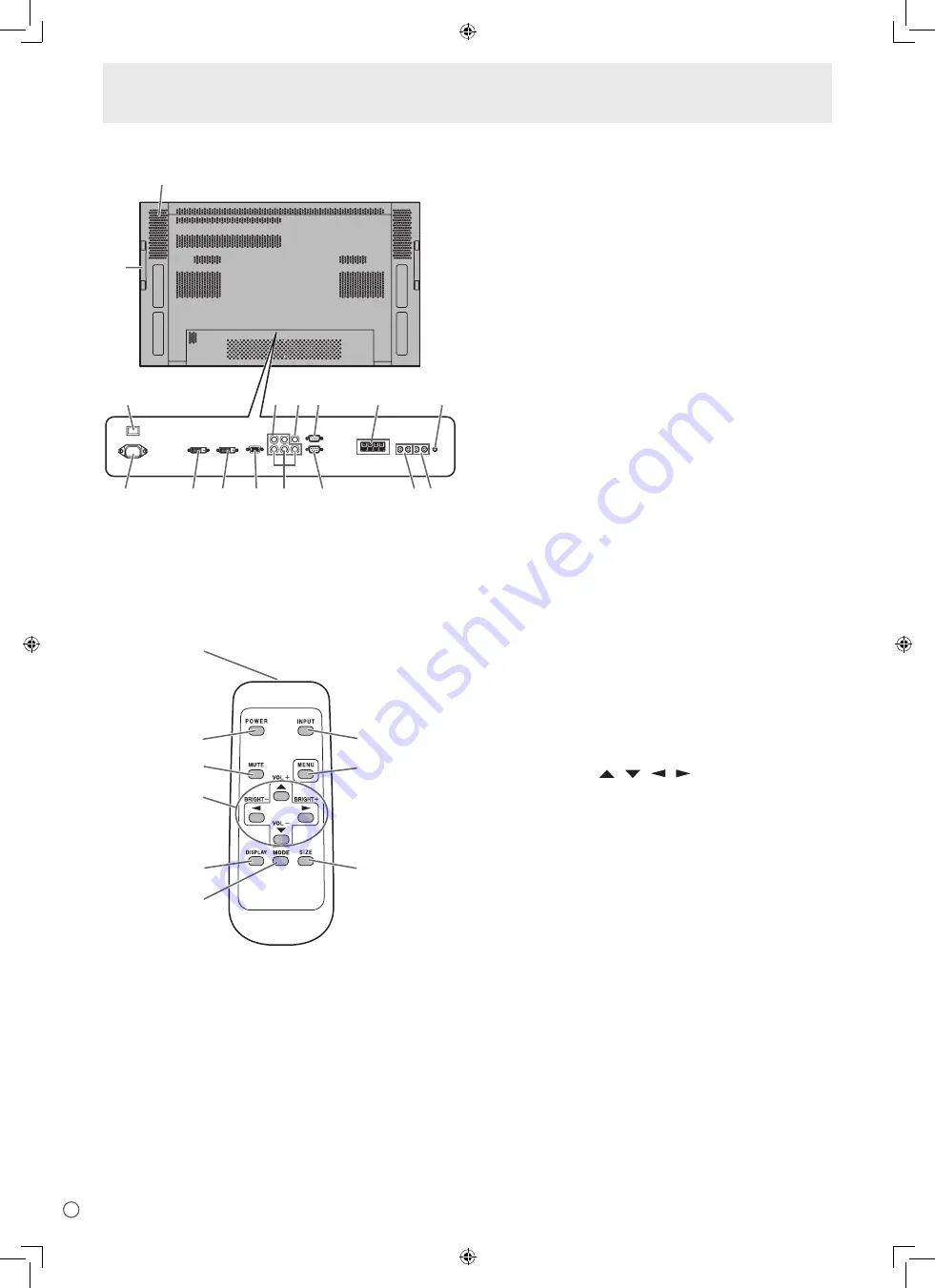
Part Names

Rear view

1

6 8 9

11

14

2

3

4

5

7

10

12 13

15

16


1.  Main power switch

 (See page 14.)


2.  AC input terminal

 (See page 12.)


3.  PC/AV output terminal (DVI-D)

 (See page 11.)


4.  PC1 input terminal (DVI-D)

 (See page 10.)


AV1 input terminal (DVI-D)

 (See page 10.)


5.  PC2 input terminal (Mini D-sub 15 pin)

 (See page 10.)


6.  PC3 input terminals (BNC)

 (See page 10.)


7.  AV2 input terminals (BNC)

 (See page 10.)


8.  AV3 input terminal (BNC)

 (See page 10.)


9.  RS-232C output terminal (D-sub 9 pin)

 (See page 25.)


10.  RS-232C input terminal (D-sub 9 pin)

 (See page 25.)


11.  External speaker terminals

 (See page 11.)


12.  PC/AV audio output terminals

 (See page 11.)


13.  AV audio input terminals

 (See page 10.)


14.  PC audio input terminal

 (See page 10.)


15.  Handles


16.  Vents

Remote control unit

1

2
3

4

5

6

9

8

7


1.  Signal transmitter


2.  POWER button

 (See page 14.)


3.  MUTE button

 (See page 15.)


4.  VOL +/- buttons

 (See page 15.)


/- buttons

 (See page 15.)


Cursor control (  /   /   /  ) buttons


5.  DISPLAY button

 (See page 15.)


6.  MODE button

 (See page 15.)


7.  INPUT button

 (See page 15.)


8.  MENU button

 (See page 17.)


9.  SIZE button

 (See page 15.)

Summary of Contents for PN-465U

Page 1: ...ENGLISH FRANÇAIS PN 465U LCD MONITOR MONITEUR LCD OPERATION MANUAL MODE D EMPLOI ENGLISH E1 FRANÇAIS F1 ...

Page 2: ......

Page 3: ...SHOCK DO NOT REMOVE COVER NO USER SERVICEABLE PARTS INSIDE REFER SERVICING TO QUALIFIED SERVICE PERSONNEL The lightning flash with arrowhead symbol within an equilateral triangle is intended to alert the user to the presence of uninsulated dangerous voltage within the product s enclosure that may be of sufficient magnitude to constitute a risk of electric shock to persons The exclamation point withi...

Page 4: ...an radiate radio frequency energy and if not installed and used in accordance with the instruction manual may cause harmful interference to radio communications Operation of this equipment in a residential area is likely to cause harmful interference in which case the user will be required to correct the interference at his own expense U S A ONLY IMPORTANT INFORMATION Continued This product utiliz...

Page 5: ... similar surface since they can block ventilation openings Do not place the product in an enclosed place such as a bookcase or rack unless proper ventilation is provided or the manufacturer s instructions are followed 9 Power cord protection The power cords must be routed properly to prevent people from stepping on them or objects from resting on them 10 The LCD panel used in this product is made ...

Page 6: ...t on a wall be sure to install the product according to the method recommended by the manufacturer 18 Heat sources Keep the product away from heat sources such as radiators heaters stoves and other heat generating products including amplifiers 19 Usage of the monitor must not be accompanied by fatal risks or dangers that could lead directly to death personal injury severe physical damage or other l...

Page 7: ...likelihood of high temperature as this may lead to generation of excessive heat and outbreak of fire The Power Cord Do not damage the power cord nor place heavy objects on it stretch it or over bend it Also do not add extension cords Damage to the cord may result in fire or electric shock Use only the power cord supplied with the monitor Insert the power plug directly into the AC outlet Adding an ex...

Page 8: ...er Cord 12 Mounting the Temporary Stands 12 Binding Cables 13 Preparing the Remote Control Unit 13 Setting the batteries 13 Remote control operation range 13 Basic Operation Turning Power On Off 14 Turning on the main power 14 Turning power on off 14 Disabling power on off operations 14 Basic Operation 15 Menu Items 17 Displaying the menu screen 17 Menu item details 18 Adjustments for PC screen di...

Page 9: ...the SHARP logo to cover the logo Vertical logo sticker 2 Sharp Corporation holds authorship rights to the Utility Disk program Do not reproduce it without permission For environmental protection Do not dispose of batteries in household garbage Follow the disposal instructions for your area Part Names Front view INPUT 1 2 3 4 5 1 LCD panel 2 Remote control sensor See page 13 3 Input switch See page...

Page 10: ... 10 9 RS 232C output terminal D sub 9 pin See page 25 10 RS 232C input terminal D sub 9 pin See page 25 11 External speaker terminals See page 11 12 PC AV audio output terminals See page 11 13 AV audio input terminals See page 10 14 PC audio input terminal See page 10 15 Handles 16 Vents Remote control unit 1 2 3 4 5 6 9 8 7 1 Signal transmitter 2 POWER button See page 14 3 MUTE button See page 15...

Page 11: ...g operation Be aware that heat emitted from the monitor may discolour or alter the wall If it is difficult to provide such space because the monitor is installed inside a housing or for other reasons take other measures to keep the ambient temperature between 32 F 0 C and 104 F 40 C such as installing a fan in the housing Adhere to the following when installing the monitor in the vertical orientat...

Page 12: ...be displayed correctly on PC3 BNC In this case check the settings of your computer graphics board to verify that input signals conform to specifications of this monitor Hsync 66 3 kHz Vsync 60 Hz and Dot frequency 148 5 MHz See page 35 If there is a check box to disable EDID in display control panel check it when using PC3 BNC Use the automatic screen adjustment when a PC screen is displayed for th...

Page 13: ...atible RS 232C input output terminals You can control the monitor from a PC by connecting a commercially available RS 232C straight cable between this terminal and the PC See page 25 Connecting external speakers Be sure to use external speakers with an impedance of 6 ohms and a rated input of at least 7 W 1 2 1 While pushing the tab insert the tip of the cable 2 Release the tab TIPS Be sure to con...

Page 14: ...outlet Power cord Supplied Power outlet AC input terminal 3 2 1 Main power switch Caution The monitor is heavy It must be handled by 2 or more people Please note that the temporary stands are for temporary use only until the monitor is properly mounted The temporary stand can be mounted at a position shown in the illustration Remove the screws from the monitor and mount the temporary stand using t...

Page 15: ...t or strong lighting Objects between the remote control unit and the remote control sensor may prevent proper operation Replace the batteries when they run low as this may shorten the remote control s operation range If a fluorescent light is illuminated near the remote control unit it may interfere with proper operation Do not use it with the remote control of other equipment such as air condition...

Page 16: ...he SCHEDULE flashes the power LED alternately in red and orange in standby mode Date time setting If the time has yet to be set when the monitor is first turned on the date time setting screen appears Set the date and time DATE TIME SETTING SET CANCEL 07 OK MENU 20 01 01 00 00 1 Press or to select the date and time and press or to change the numerical values 2 Select SET and then press MENU Be sure ...

Page 17: ...tons for about 4 seconds the VOLUME menu automatically disappears 5 BRIGHT Backlight adjustment Pressing or displays the BRIGHT menu when the menu screen is not displayed B R I G H T 15 Press or to adjust the brightness If you do not press any buttons for about 4 seconds the BRIGHT menu automatically disappears 6 SIZE Screen size selection The menu is displayed Press or to select the screen size S...

Page 18: ...itor s screen size switching or dual screen display functions to compress or expand the screen for commercial or public viewing in establishments like cafes or hotels may infringe on the rights of the creators as protected by Copyright Law so please be careful When Enlarge is set the screen size is fixed to WIDE mode When dual screen display is selected the screen size cannot be changed The appeara...

Page 19: ... 48 4 kHz 4 Press or to adjust the setting AUTO CONTRAST BLACK LEVEL SHARPNESS 40 96 12 PC2 ANALOG 1 2 PICTURE SCREEN PICTURE AUDIO SETUP OPTION ENLARGE PIP PbyP OK MENU 1 0 2 4 x 7 6 8 V 60 Hz H 48 4 kHz For items that have press make settings and then press MENU 5 Press MENU twice to close the menu screen TIPS The menu will differ depending on the input mode The menu screen will close automatica...

Page 20: ...ts the hue Selecting changes the color towards green and selecting changes it towards magenta COLORS AV input Adjusts the color intensity SHARPNESS Adjusts the sharpness of the image ADVANCED AV input You can adjust more specifically See page 22 COLOR MODE Changes the color mode on the screen The color mode on the screen can also be changed using a remote control unit See page 15 sRGB is PC input o...

Page 21: ...ppear STANDARD MIRROR ROTATE UPSIDE DOWN ABC A B C ABC ABC POWER ON DELAY You can delay the screen display after the monitor is turned on The period can be set up to 60 seconds in units of one second When this function is activated the power LED flashes at approx 1 second interval in orange This function is disabled when 0 is specified OPTION DATE TIME SETTING Set the date and time Press or to selec...

Page 22: ...ng adjustments of ADVANCED are invalid and adjusting is disabled 3D NR MPEG NR and 3D Y C ENLARGE PC input ENLARGE MODE Sets the number of screen splits used for the enlargement See page 21 ENLARGE POS Specify the split screen to be displayed when the enlargement function is used See page 21 BEZEL H BEZEL V Sets the frame width of the display when the enlargement function is used H POS Adjust the ...

Page 23: ... 20 21 22 23 4 9 14 19 24 Original image 0 1 2 4 5 6 8 9 10 3 7 11 12 13 14 15 0 1 2 5 6 7 10 11 12 3 8 13 15 16 17 18 20 21 22 23 4 9 14 19 24 Original image In horizontal orientation In vertical orientation 0 1 2 3 4 5 6 7 8 0 1 2 3 4 5 6 7 8 TIPS AV input signals cannot be used for the Enlarge function To integrate 9 or more monitors using PC1 signals a splitter for the video signal commerciall...

Page 24: ...SCHEDULE every day regardless of the day of the week 4 TIME Specifies the time to execute the SCHEDULE 5 INPUT Specifies the input mode at power on When not specifying the screen at the previous power off appears Input modes displayed on PC1 AV1 depend on DVI SELECT settings Input modes displayed on PC3 AV2 depend on BNC SELECT settings Caution Do not switch off the main power after setting the SCHE...

Page 25: ...stment if necessary Screen display for adjustment Before making adjustments in the SCREEN menu or PICTURE menu display an image to brighten the entire screen If you are using a Windows PC use the adjustment pattern on the supplied CD ROM Opening the adjustment pattern 1 Load the supplied CD ROM into the computer s CD ROM drive 2 Open the CD ROM in My Computer 3 Double click Adj_uty exe The adjustm...

Page 26: ...on ADJUSTMENT LOCK You can disable operations on the monitor and the remote control unit that use buttons OFF Enables operation 1 Disables all operations other than turning power on off and FUNCTION 2 Only the FUNCTION operation is enabled Disables all operations other than FUNCTION not even power on off OSD DISPLAY Hides shows menus The FUNCTION screen cannot be hidden ON Displays the menus OFF H...

Page 27: ...t RS 232C output terminal RS 232C input terminal Communication conditions Set the RS 232C communication settings on the PC to match the monitor s communication settings as follows Baud rate 9600 bps Stop bit 1 bit Data length 8 bits Flow control None Parity bit None Communication procedure Command format When a command is sent from the PC to the monitor the monitor operates according to the receiv...

Page 28: ...lowing commands is used RSET INPS ASNC WIDE EMAG EPOS PXSL POWR AGIN MWIN MWIP MWPP ESTG When control via RS 232C is locked to prevent use using the operation lock function see page 24 E C D K O L Return code 0DH 0AH Communication interval After OK or ERR is returned you must send the following commands To set a timeout for the command response specify 10 seconds or longer Provide an interval of 1...

Page 29: ...or with ID number 2 VOLM0020 Sets volume to 20 OK 001 The volume of the monitor with ID number 1 the one directly connected to the PC is set to 20 The IDSL command is effective only once for the immediately succeeding command IDLK The parameter of this command sets the ID number of the monitor The monitor is subject to all subsequent commands Example IDLK0002 Following commands are for the monitor...

Page 30: ...value has been returned by a specific set assign ID numbers to each monitor in advance When some monitors do not return their responses the probable cause is that the monitors could not receive the command or command processing is not complete Do not send a new command Example When 4 monitors are connected and assigned ID numbers 1 through 4 VOLM030 WAIT OK 001 OK 002 OK 003 OK 004 If 4 monitors ar...

Page 31: ...dby mode Yes 1 Returns from standby mode R 0 Standby mode 1 Normal mode 2 Input signal waiting mode INPUT MODE SELECTION INPS W 0 Toggle change for input mode Terminals not selected in DVI SELECT BNC SELECT cannot be selected Yes 1 PC1 DIGITAL ERR when AV DIGITAL is selected for DVI SELECT 2 PC2 ANALOG 3 AV2 COMPONENT ERR when PC ANALOG is selected for BNC SELECT 4 AV3 VIDEO 6 PC3 ANALOG ERR when ...

Page 32: ...CE AUBL WR 10 10 10 10 RESET ARST W 3 No SETUP menu Function Command Direction Parameter Reply Control Response contents SCREEN MOTION SCSV WR 0 4 0 4 0 OFF 1 4 PATTERN 1 4 Yes MOTION TIME 1 MTIM WR 0 20 0 20 Yes MOTION TIME 2 PATTERN 1 MINT WR 10 990 10 990 Per 10 seconds Yes PATTERN 2 4 MINT WR 5 20 5 20 Per second MONITOR STDR WR 0 1 0 1 0 LANDSCAPE 1 PORTRAIT Yes LANGUAGE LANG WR 14 14 ENGLISH...

Page 33: ...ol Response contents ENLARGE MODE EMAG WR 0 4 0 4 0 OFF 1 2 x 2 2 3 x 3 3 4 x 4 4 5 x 5 No BEZEL WIDTH WIDTH OF THE SHORTER SIDE BEZH WR 0 100 0 100 WIDTH OF THE LONGER SIDE BEZV WR 0 100 0 100 IMAGE POSITION 2 x 2 EPOS WR 0 3 0 3 See page 21 IMAGE POSITION 3 x 3 EPOS WR 0 8 0 8 IMAGE POSITION 4 x 4 EPOS WR 0 15 0 15 IMAGE POSITION 5 x 5 EPOS WR 0 24 0 24 ENLARGED SCREEN POSITIONING THE LONGEST DI...

Page 34: ...GHT VLMP WR 0 31 0 31 Brightness Yes TEMPERATURE SENSOR DSTA R 0 Internal temperature normal Yes 1 Internal temperature abnormal Standby mode 2 Internal temperature abnormal Temperature is normal now but it was abnormal during operation 3 Internal temperature abnormal Brightness of the backlight decreases 4 Temperature sensor abnormal TEMPERATURE ACQUISITION ERRT R Value Temperature at temperature...

Page 35: ...en turn the power on again PC3 or AV2 does not appear properly Is the setting of BNC SELECT correct See page 19 Is the input signal compatible with this monitor See page 35 Control buttons do not work There is no picture Some kind of load noises from outside might interfere with normal operation Turn off the power and turn it on after waiting at least 5 seconds and then check the operation Power L...

Page 36: ...NC Y Cb Pb Cr Pr 1 x 1 Audio RCA pin L R x 1 Serial RS 232C D sub 9 pin x 1 Output terminals PC AV Digital DVI D 24 pin x 1 3 Audio RCA pin L R x 1 Serial RS 232C D sub 9 pin x 1 Speaker 7 W 7 W 6 Ω Power requirement AC 120 V 60 Hz Operating temperature 32 F to 104 F 0 C to 40 C Operating humidity 20 to 80 no condensation Power consumption 266 W Input signal waiting mode 6 5 W Standby mode 3 5 W D...

Page 37: ...Yes Yes Yes Yes Yes Yes Yes Yes Yes Yes Yes Yes Yes Yes Yes Yes Yes Yes Yes Yes Yes Yes Yes Yes Yes Yes Yes Yes Yes Digital signal Yes Yes Yes Yes Yes Yes Yes Yes Yes Yes Yes Yes Yes Yes Yes Yes Yes Yes Yes Yes Yes 1 Displays a reduced image All are compliant only with non interlaced Depending on the connected PC images may not be displayed properly even if the compatible signal described above is...

Page 38: ...12 Function TMDS data 2 TMDS data 2 TMDS data 2 4 shield N C N C DDC clock DDC data N C TMDS data 1 TMDS data 1 TMDS data 1 3 shield N C No 13 14 15 16 17 18 19 20 21 22 23 24 Function N C 5 V GND Hot plug detection TMDS data 0 TMDS data 0 TMDS data 0 5 shield N C N C TMDS clock shield TMDS clock TMDS clock Specifications Power management This monitor conforms to VESA DPMS and DVI DMPM Both your vi...

Page 39: ... Y A AUCUNE PIÈCE RÉPARABLE PAR L UTILISATEUR À L INTÉRIEUR AVERTIR LE PERSONNEL DE SERVICE QUALIFIÉ POUR TOUTE PROCÉDURE D ENTRETIEN Le symbôle représenté par l éclair à la tête en pointe de flèche à l intérieur d un triangle équilatéral est placé pour alerter l utilisateur de la présence d une tension dangereuse non isolée à l intérieur du produit Cette tension peut avoir une valeur suffisante pou...

Page 40: ... sous forme de radiofréquences et s il n est pas installé et utilisé conformément aux instructions du mode d emploi peut provoquer des interférences nuisibles aux communications par radio Le fonctionnement de cet équipement dans une zone résidentielle peut vraisemblablement provoquer des interférences nuisibles auquel cas l utilisateur est prié de corriger ces interférences à ses propres frais ÉTA...

Page 41: ...r une surchauffe et réduire la durée de vie de l appareil Ne placez pas l appareil sur un sofa un tapis ou toute autre surface analogue car ceci pourrait obstruer les ouvertures de ventilation Cet appareil n est pas conçu pour une installation encastrée ne le placez donc pas dans un endroit fermé comme une bibliothèque ou une baie à moins qu une ventilation adéquate ne soit prévue et que les consi...

Page 42: ...icant 18 Sources de chaleur Tenez l appareil à l écart de sources de chaleur telles que radiateurs dispositifs de chauffage poêles et autres appareils dégageant de la chaleur y compris les amplificateurs 19 L utilisation de ce moniteur ne doit pas entraîner des risques mortels ou des dangers qui pourraient provoquer directement la mort des blessures sur le personnel des dommages physiques sévères o...

Page 43: ...voquer un début d incendie Le cordon d alimentation N endommagez pas le cordon d alimentation ne déposez pas d objets lourds sur le cordon d alimentation ne tirez pas dessus et ne le pliez pas de manière excessive De même n ajoutez pas de rallonges Tout endommagement du cordon d alimentation peut provoquer un début d incendie ou un choc électrique Utilisez seulement le cordon d alimentation fourni...

Page 44: ...es 12 Fixation des câbles 13 Mise en service de la télécommande 13 Mise en place des piles 13 Portée de la télécommande 13 Opérations de base Mise sous tension et hors tension 14 Mise sous tension de l interrupteur principal 14 Mise sous hors tension 14 Neutralisation des fonctions de mise sous hors tension 14 Fonctionnement de base 15 Options de menu 17 Affichage de l écran de menu 17 Détails des ...

Page 45: ...logo SHARP pour le couvrir Sharp Corporation détient les droits d auteur du programme de l Utility Disk Veuillez ne pas le reproduire sans autorisation de la société Pensez à votre environnement Ne pas jeter les piles avec les ordures ménagères exige un traitement spécial Nomenclature Vue de face INPUT 1 2 3 4 5 1 Panneau LCD 2 Capteur de télécommande Voir à la page 13 3 Interrupteur d entrée Voir...

Page 46: ... Voir à la page 25 10 Borne d entrée RS 232C D sub à 9 broches Voir à la page 25 11 Bornes haut parleur externe Voir à la page 11 12 Bornes de sortie audio du PC de l AV Voir à la page 11 13 Bornes d entrée audio de l AV Voir à la page 10 14 Borne d entrée audio du PC Voir à la page 10 15 Poignées 16 Ouvertures de ventilation Télécommande 1 2 3 4 5 6 9 8 7 1 Émetteur de signal 2 Bouton POWER alime...

Page 47: ...le moniteur peut décolorer ou altérer le mur S il est difficile de laisser un tel espace parce que le moniteur est installé dans une enceinte ou pour d autres raisons prenez d autres mesures pour maintenir la température ambiante entre 0 C et 40 C telles que l installation d un ventilateur à l intérieur de l enceinte Respectez la condition suivante quand vous installez le moniteur dans la directio...

Page 48: ...tement sur PC3 BNC Dans ce cas vérifiez les réglages de votre ordinateur carte vidéo pour contrôler que les signaux d entrée sont conformes aux spécifications de ce moniteur Hsync 66 3 kHz Vsync 60 Hz et Fréquence du point 148 5 MHz Voir à la page 35 S il y a une case à cocher pour désactiver EDID sur le panneau de commande d affichage cochez le quand vous utilisez PC3 BNC Utilisez le réglage automat...

Page 49: ...ment qui n est pas compatible HDCP Bornes d entrée sortie RS 232C Vous pouvez contrôler le moniteur à partir d un PC en raccordant un câble direct RS 232C en vente dans le commerce entre cette borne et le PC Voir à la page 25 Connexion des haut parleurs externes Assurez vous que vous utilisez des haut parleurs externes avec une impédance de 6 ohms et une puissance nominale d au moins 7 W 1 2 1 Tou...

Page 50: ...ni à la prise d alimentation secteur Cordon d alimentation fourni Prise d alimentation Borne d entrée secteur 3 2 1 Interrupteur principal Attention Le moniteur pèse lourd Il doit être manipulé par 2 ou plus de 2 personnes Notez bien que les supports temporaires sont à usage temporaire uniquement en attendant que le moniteur soit correctement installé Le support temporaire peut être monté dans une...

Page 51: ... télécommande peuvent l empêcher de fonctionner correctement Remplacez les piles lorsque leurs charges baissent car elles peuvent diminuer la portée de la télécommande Si une lampe fluorescente est allumée près de la télécommande cela peut altérer son fonctionnement Ne vous servez pas de la télécommande d un autre appareil tel qu un conditionneur d air ou un équipement stéréo etc Mise en service de...

Page 52: ...ter la diode d alimentation alternativement en rouge et en orange dans le mode veille Réglage de la date heure Si l heure doit être réglée lorsque le moniteur est mis sous tension pour la première fois l écran de réglage de la date heure apparaît Réglez la date et l heure DATE TIME SETTING SET CANCEL 07 OK MENU 20 01 01 00 00 1 Appuyez sur ou pour sélectionner la date et l heure puis appuyez sur o...

Page 53: ...ant environ 4 secondes le menu de VOLUME disparaît automatiquement 5 LUMINOSITÉ Réglage du rétroéclairage Appuyer sur ou affiche le menu BRIGHT LUMIN lorsque l écran de menu n est pas affiché B R I G H T 15 Appuyez sur ou pour régler la luminosité Si vous n appuyez sur aucun bouton pendant environ 4 secondes le menu de BRIGHT LUMIN disparaît automatiquement 6 DIMENSION Sélection de la dimension de l...

Page 54: ...ns des établissements tels que des cafés ou des hôtels peut constituer une violation des droits des créateurs protégés par la loi sur les droits d auteur veuillez en tenir compte Lorsque c est réglé sur la fonction Enlarge Agrandissement la dimension de l écran est fixée au mode WIDE LARGE Quand l affichage sur deux écrans est sélectionné la dimension de l écran ne peut pas être changée L aspect de ...

Page 55: ...ur ou pour ajuster le réglage AUTO CONTRAST BLACK LEVEL SHARPNESS 40 96 12 PC2 ANALOG 1 2 PICTURE SCREEN PICTURE AUDIO SETUP OPTION ENLARGE PIP PbyP OK MENU 1 0 2 4 x 7 6 8 V 60 Hz H 48 4 kHz Pour les options qui sont marquées appuyez sur faites les réglages puis appuyez sur MENU 5 Appuyez sur MENU deux fois pour fermer l écran de menu Conseils Le menu va différer en fonction du mode d entrée L éc...

Page 56: ...a couleur vers le magenta COLORS COULEUR Entrée AV Règle l intensité de chrominance SHARPNESS NETTETÉ Règle la définition de l image ADVANCED AVANCÉ Entrée AV Vous pouvez régler plus spécialement Voir à la page 22 COLOR MODE MODE COULEUR Change le mode de couleur sur l écran Le mode de couleur sur l écran peut également être changé en utilisant une télécommande Voir à la page 15 sRGB est seulement ...

Page 57: ...IRROR MIROIR ROTATE ROTATION UPSIDE DOWN INVERSÉ ABC A B C ABC ABC POWER ON DELAY RETARD MARCHE Vous pouvez retarder l affichage de l écran après avoir mis sous tension le moniteur La période peut être réglée jusqu à 60 secondes par unités d une seconde Lorsque cette fonction est activée la diode d alimentation clignote en orange environ à intervalle d une seconde Cette fonction est désactivée lors...

Page 58: ...uand l affichage sur deux écrans est sélectionné les réglages suivants de ADVANCED AVANCÉ sont invalides et le réglage est désactivé 3D NR MPEG NR et 3D Y C ENLARGE AGRANDIR Entrée du PC ENLARGE MODE MODE LARGE Règle le nombre d éléments de l écran utilisés pour l agrandissement Voir à la page 21 ENLARGE POS POS AGRANDIR Précise l écran élémentaire à afficher quand la fonction d agrandissement est u...

Page 59: ...ginale 0 1 2 4 5 6 8 9 10 3 7 11 12 13 14 15 0 1 2 5 6 7 10 11 12 3 8 13 15 16 17 18 20 21 22 23 4 9 14 19 24 Image originale Dans la direction horizontale Dans la direction verticale 0 1 2 3 4 5 6 7 8 0 1 2 3 4 5 6 7 8 Conseils Les signaux d entrée AV ne peuvent pas être utilisés dans la fonction Enlarge Agrandissement Pour intégrer 9 moniteurs ou plus en utilisant les signaux PC1 un séparateur d...

Page 60: ... Spécifie l heure pour l exécution de SCHEDULE 5 INPUT ENTRÉE Précise le mode d entrée à la mise sous tension Quand elle n est pas spécifiée l écran à la mise hors tension précédente apparaît Les modes d entrée affichés sur PC1 AV1 dépendent des réglages de DVI SELECT Les modes d entrée affichés sur PC3 AV2 dépendent des réglages de BNC SELECT Attention Ne mettez pas hors tension l interrupteur princi...

Page 61: ...églage Avant de faire des réglages dans le menu SCREEN ÉCRAN ou le menu PICTURE IMAGE affichez une image pour éclaircir tout l écran Si vous utilisez un PC sous Windows utilisez la mire de réglage sur le CD ROM fourni Dans ce mode d emploi tous les termes de Windows sont en Anglais Ouverture de la mire de réglage 1 Chargez le CD ROM fourni dans le lecteur de CD ROM de l ordinateur 2 Ouvrez le CD RO...

Page 62: ... télécommande qui utilisent les boutons OFF Active la fonction 1 Désactive toutes les fonctions autres que la mise sous hors tension et la fonction FUNCTION 2 Seule la fonction FUNCTION est activée Désactive toutes les fonctions autres que FUNCTION pas même la mise sous hors tension OSD DISPLAY OSD Cache affiche les menus L écran FUNCTION ne peut pas être caché ON Affiche les menus OFF Cache les men...

Page 63: ...e d entrée RS 232C Conditions de communication Faites les réglages de communication RS 232C du PC pour qu ils correspondent aux réglages de communication du moniteur comme suit Débit en bauds 9 600 bps Bit d arrêt 1 bit Longueur des données 8 bits Commande de flux Aucun Bit de parité Aucun Procédure de communication Format des commandes Lorsqu une commande est envoyée de l ordinateur au moniteur le...

Page 64: ... liaison RS232C a été verrouillée pour empêcher son emploi en utilisant la fonction verrouillage des commandes voir à la page 24 E C D K O L Code retour 0DH 0AH Intervalle de communication Après le renvoi de OK ou ERR vous devez envoyer les commandes suivantes Pour régler l expiration du délai spécifiez 10 secondes ou un temps plus long Fournit un intervalle de 100 ms ou plus entre la réponse à une...

Page 65: ...tion est égal à 2 VOLM0020 Règle le volume sonore à 20 OK 001 Le volume sonore du moniteur dont le numéro d identification est égal à 1 celui qui est raccordé directement au PC est réglé à 20 La commande IDSL est effective une fois seulement pour la commande qui la suit immédiatement IDLK Le paramètre de cette commande désigne le numéro d identification du moniteur Ce moniteur sera sujet à toutes le...

Page 66: ...avance des numéros d identification à chaque moniteur Quand certains moniteurs ne renvoient pas de réponses la cause probable est que ces moniteurs ne pouvaient pas recevoir la commande ou que le traitement de la commande n est pas terminé N envoyez pas de nouvelle commande Exemple Lorsque 4 moniteurs sont raccordés et que les numéros d identification 1 à 4 leur ont été affectés VOLM030 WAIT OK 001 ...

Page 67: ...ection du mode d entrée INPS W 0 Changement en basculant sur mode d entrée Les bornes non sélectionnées dans DVI SELECT DVI SÉLECTION BNC SELECT BNC SÉLECTION ne peuvent pas être sélectionnées Oui 1 PC1 DIGITAL PC1 NUMÉRIQUE ERR quand AV DIGITAL AV NUMÉRIQUE est sélectionné pour DVI SELECT DVI SÉLECTION 2 PC2 ANALOG PC2 ANALOGIQUE 3 AV2 COMPONENT AV2 COMPOSANT ERR quand PC ANALOG PC ANALOGIQUE est...

Page 68: ...Paramètre Réponse Contenu de la commande de la réponse SCREEN MOTION DÉFILEMENT IMAGE SCSV WR 0 4 0 4 0 OFF 1 4 PATTERN 1 4 MIRE 1 4 Oui MOTION TIME 1 DÉFILEMENT TEMPS 1 MTIM WR 0 20 0 20 Oui MOTION TIME 2 DÉFILEMENT TEMPS 2 PATTERN 1 MIRE 1 MINT WR 10 990 10 990 Toute les 10 secondes Oui PATTERN 2 4 MIRE 2 4 MINT WR 5 20 5 20 Par seconde MONITOR MONITEUR STDR WR 0 1 0 1 0 LANDSCAPE PAYASAGE 1 POR...

Page 69: ...n actuelle sous la forme hhh vvv Non RÉGLAGE DES PIXELS PC2 PC3 PXSL WR 1 1 V 768 1 360 x 768 2 2 V 768 1 280 x 768 3 3 V 768 1 024 x 768 5 5 V 480 848 x 480 6 6 V 480 640 x 480 Résolution à l entrée AV Contrôle de la résolution RESO R 480i 480p 1080i 720p 1080p VGA etc Non SELF ADJUST AUTORÉGLAGE AADJ WR 0 1 0 1 0 OFF 1 ON Oui POWER MANAGEMENT GESTION DE L ALIMENTATION PMNG WR 0 1 0 1 0 OFF 1 ON ...

Page 70: ...OFF Oui LED OFLD WR 0 1 0 1 0 ON 1 OFF Oui Autres Fonction Commande Direction Paramètre Réponse Contenu de la commande de la réponse DIMENSION DE L ÉCRAN PC WIDE WR 1 5 1 5 1 WIDE LARGE 2 NORMAL 3 DotbyDot Pt par Pt 4 ZOOM1 5 ZOOM2 Oui DIMENSION DE L ÉCRAN AV WIDE WR 1 5 1 5 1 WIDE LARGE 2 ZOOM1 3 ZOOM2 4 NORMAL 5 DotbyDot Pt par Pt Oui VOLUME VOLM WR 0 31 0 31 Oui MUTE MUTE WR 0 1 0 1 0 OFF 1 ON ...

Page 71: ...Voir à la page 19 Le signal d entrée est il compatible avec ce moniteur Voir à la page 35 Les boutons de commande ne fonctionnent pas Il n y a pas d image Quelques sortes de bruits provenant de l extérieur peuvent interférer sur le fonctionnement normal Coupez l alimentation puis remettez la aprés avoir attendu au moins 5 secondes et ensuite vérifiez le fonctionnement La diode d alimentation cligno...

Page 72: ...ant BNC Y Cb Pb Cr Pr 1 x 1 Audio Broche RCA G D x 1 Système de raccordement D sub 9 broches x 1 en série RS232C Bornes de sortie PC AV Numérique DVI D à 24 broches x 1 3 Audio Broche RCA G D x 1 Système de raccordement D sub 9 broches x 1 en série RS232C Haut parleurs 7 W 7 W 6 Ω Alimentation CA 120 V 60 Hz Température de fonctionnement 0 C à 40 C Hygrométrie de fonctionnement 20 à 80 sans conden...

Page 73: ...Oui Oui Oui Oui Oui Oui Oui Oui Oui Oui Oui Oui Oui Oui Oui Oui Oui Oui Oui Oui Oui Oui Oui Oui Signal numérique Oui Oui Oui Oui Oui Oui Oui Oui Oui Oui Oui Oui Oui Oui Oui Oui Oui Oui Oui Oui Oui 1 Affiche une image réduite Tous sont conformes seulement aux signaux non entrelacés Selon le PC connecté des images peuvent ne pas être correctement affichées même si un signal compatible décrit ci dessu...

Page 74: ... C DDC horloge DDC donnée N C TMDS donnée 1 TMDS donnée 1 TMDS donnée 1 3 blindage N C No 13 14 15 16 17 18 19 20 21 22 23 24 Fonction N C 5 V MASSE Détection connexion à chaud TMDS donnée 0 TMDS donnée 0 TMDS donnée 0 5 blindage N C N C TMDS horloge blindage TMDS horloge TMDS horloge Caractéristiques Gestion de l alimentation Ce moniteur est conforme aux systèmes VESA DPMS et DVI DMPM La carte vi...

Page 75: ......

Page 76: ...Printed on 100 post consumer recycled paper Imprimé sur 100 de papier recyclé Printed in Japan Imprimé au Japon TINSE1111MPZZ 1 07J DSC1 ...

Reviews: