17
PG-M10SU/SE
PG-M10XU/XE
OPTICAL ADJUSTMENT AND MEASURING
1.Adjustment of color wheel sensor
●
Adjustment needed
1. When the color wheel unit has been replaced
2. When the color wheel sensor has been replaced
3. When the optical drive unit has been replaced (if a deviation from normal setting is found)
4. When the F/E PWB has been replaced (if a deviation from normal setting is found)
●
Tools required
1. Personal computer (run on Windows 95/98)
2. RGB cable
3. Dedicated application program (white.exe program commonly used for both models UP and U2)
4. Wrench (5 mm)
5. Projection screen (normally white)
Note: During the adjustment, be careful not to touch the lamp and other hot components.
●
Procedure
1. Adjustment should be done with the top cover and
the front panel removed.
2. Connect the projector to the PC (RGB mode).
3. Start up the dedicated application program
(white.exe) on the PC.
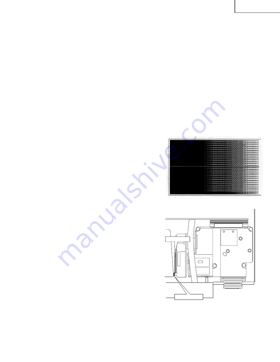
4. Press the "6" key on the keyboard. After the pattern
shown in Fig. 1 at right has appeared, press the
"R" key to get the red image displayed for checking.
Check the other colors as well (*1).
5. When part of the image does not appear in red,
loosen the wheel screw shown in Fig. 2 below and
slide the wheel sensor up or down. Fix the wheel
sensor again at the position where the color
deviation disappears.
6. Finally press the "Q" key on the keyboard to finish
the program.
Fig.1
●
1:The basic black and white patterns are registered in the numeric keys 0 thru 9 on the keyboard. The colors can be
changed to any of White(W), Black(K), Red(R), Green(G), Blue(B), Magenta(M) and Cyanic(C).
Wheel Screw
Wheel Sensor
Fig.2
Summary of Contents for PG-M10SE
Page 2: ...2 PG M10SU SE PG M10XU XE Specifications ...
Page 4: ...4 PG M10SU SE PG M10XU XE Location of Controls ...
Page 5: ...5 PG M10SU SE PG M10XU XE ...
Page 6: ...6 PG M10SU SE PG M10XU XE Reomte Control ...
Page 7: ...7 PG M10SU SE PG M10XU XE Connections ...
Page 8: ...8 PG M10SU SE PG M10XU XE ...
Page 9: ...9 PG M10SU SE PG M10XU XE Pin Assignments Dimensions ...


