Sharp MX-M350 Service Manual Download Page 114

MX-M350/M450 N/U  MAINTENANCE AND DETAILS OF EACH SECTION  7 - 68

10. Drive section

A. Maintenance and parts replacement

(1) Maintenance list

(2) Maintenance and parts replacement
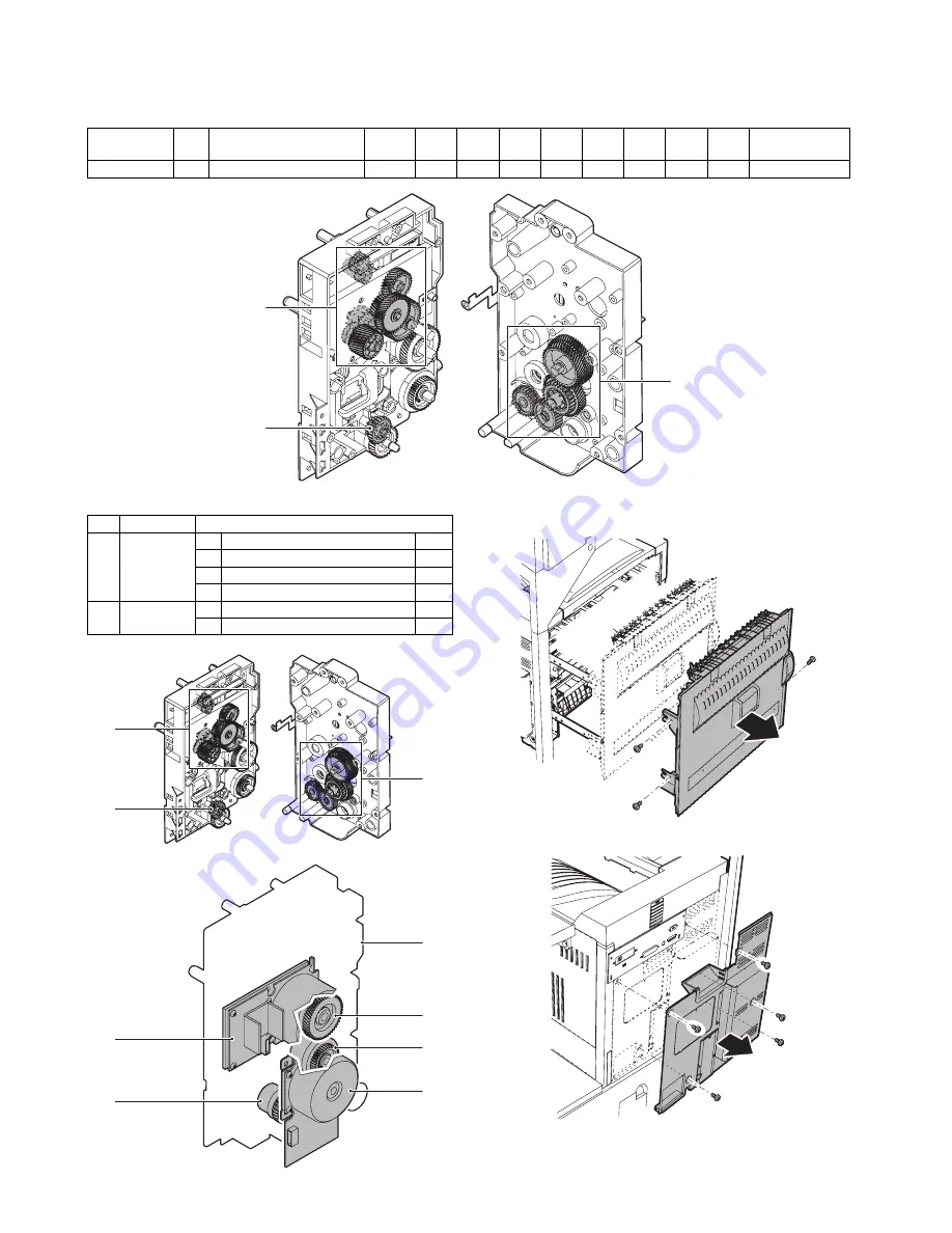
a. Drive unit

1) Remove the screw, and remove the left door.

2) Remove the screw, and remove the rear cabinet.

Unit name

No.

Part name

When 

calling

100K

200K

300K

400K

500K

600K

700K

800K

Remark

Drive section

1

Gears (Specified position)

1

1

1

No.

Unit

Parts

a

Drive unit

1

Gears

✕✩

2

Paper cassette paper feed clutch

3

Paper transport clutch

4

Resist roller clutch

b

1

Drum motor

2

Main motor

a-2

b-1

a-4

a

a-3

b-2

a-1

a-1

a-1

Summary of Contents for MX-M350

Page 1: ... change without notice SERVICE MANUAL CONTENTS SHARP CORPORATION CODE 00ZMXM450 S1E LASER PRINTER MX M350 M450 U MODEL MX M350 M450 N 1 GENERAL 1 1 2 CONFIGURATION 2 1 3 SPECIFICATIONS 3 1 4 CONSUMABLE PARTS 4 1 5 EXTERNAL VIEWS AND INTERNAL STRUCTURES 5 1 6 UNPACKING AND INSTALLATION 6 1 7 MAINTENANCE AND DETAILS OF EACH SECTION 7 1 8 ADJUSTMENTS 8 1 9 SIMULATIONS 9 1 10 MACHINE OPERATION 10 1 11...

Page 2: ...RUKSANVISNING SPECIFICERATS KAN ANVÄNDAREN UTSÄTTAS FÖR OSYNLIG LASERSTRÅLNING SOM ÖVERSKRIDER GRÄNSEN FÖR LASERKLASS 1 For North America SAFETY PRECAUTIONS This Digital Equipment is rated Class 1 and complies with 21 CFR 1040 10 and 1040 11 of the CDRH standards This means that the equipment does not produce hazardous laser radiation For your safety observe the precautions below Do not remove the...

Page 3: ...cartridge 4 5 3 Environmental conditions 4 5 A Operating conditions 4 5 B Storage conditions 4 5 5 EXTERNAL VIEWS AND INTERNAL STRUCTURES 1 Exterior 5 1 2 Interior 5 2 3 Operation panel 5 3 4 Job status screen common to print scan fax and Internet fax 5 4 5 BASE SCREEN 5 5 A Condition settings screen 5 5 B Address book screen 5 6 6 Cross sectional view 5 7 A Scanner unit 5 7 B Engine 5 7 7 Switch ...

Page 4: ...H Image density adjustment 8 13 I DSPF width detection adjustment 8 17 9 SIMULATION 1 Outline and purpose 9 1 2 Code type simulation 9 1 A Operating procedures and operations 9 1 B Simulation list 9 3 C Details 9 7 3 Other related items 9 86 10 MACHINE OPERATION 1 Acceptable originals 10 1 A Size and weight of acceptable originals 10 1 B Total number of originals that can be set in the document fe...

Page 5: ...scanner module Doing so may damage your eyes 4 Five adjusters are provided on all optional stand paper drawer units These adjusters should be lowered until they contact the floor 5 Do not make any modifications to this machine Doing so may result in personal injury or damage to the machine 6 Since this machine is heavy it is recommended that it be moved by more than one person to prevent injury 7 ...

Page 6: ... Any one of the stand MPD 2000 sheet paper drawer AR D28 the stand 3 x 500 sheet paper drawer AR D27 or the multi purpose drawer AR MU2 Any one of the upper exit tray extension AR TE4 the finisher AR FN6 the mail bin stacker AR MS1 the saddle stitch finisher AR FN7 or the right upper exit tray AR TE5 Scanner module with DSPF MX EFX1 Scanner rack AR RK2 MX M450U M450N Any one of the duplex module b...

Page 7: ...inisher AR FN6 9 Mail bin stacker AR MS1 3 Stand MPD 2000 sheet paper drawer AR D28 5 Multi purpose drawer AR MU2 4 Stand 3 x 500 sheet paper drawer AR D27 13 Saddle stitch finisher AR FN7 14 Punch module AR PN1 A B C D 12 Duplex module AR DU3 11 Duplex module bypass tray AR DU4 10 Exit tray AR TE3 The AR DU4 is a standard provision 8 Right upper exit tray AR TE5 1 Scanner module with DSPF MX EFX1...

Page 8: ...awer AR D27 or the stand MPD 2000 sheet paper drawer AR D28 is required The duplex module bypass tray AR DU4 cannot be installed with the exit tray AR TE3 or the saddle stitch finisher AR FN7 When the duplex module AR DU3 is installed the exit tray AR TE3 or the saddle stitch finisher AR FN7 is required 12 Duplex module AR DU3 13 Saddle stitch finisher AR FN7 Simultaneous installation with the fin...

Page 9: ...kit Sharpdesk 1 license kit Sharpdesk 5 license kit Sharpdesk 10 license kit PS3 e Right upper exit tray xpansion kit Facsimile expansion kit Upper exit tray F Data security kit For a model with HDD installed Data security kit For a model without HDD installed ax memory 8 MB Network scanner expansion kit Network scanner expansion kit 1 1 1 1 1 1 2 3 3 1 1 1 1 1 MX FRX6 MX FRX6U MX FRX7 MX FRX7U Da...

Page 10: ...radation Write 2 levels C C E E B D A Paper size Printable area Paper size A B C D E A3 297 420 4 289 4 B4 257 364 4 242 4 A4 210 297 4 202 4 B5 182 257 4 168 4 A5 148 210 4 140 4 Japanese postcard 100 148 4 92 4 Ledger 279 432 4 271 4 Legal 216 356 4 208 4 Foolscap 216 330 4 208 4 Letter 216 279 4 208 4 Executive 184 267 4 183 4 Invoice 140 216 4 132 4 Com 10 envelope 105 241 4 97 4 C5 envelope 1...

Page 11: ...narch 98 x 191 8K 16K 16KR Com 10 105 x 241 DL 110 x 220 C5 162 x 229 ISO B5 176 x 250 Spec of media for paper output Tracing paper 52 59g m 14 15lbs Plain paper 60 128g m 16 34lbs Index paper 176g m 47lbs Cover paper 205g m 54 55lbs Transparency firm Remaining paper detection Not available Exit tray full detection Provided IBM PC AT Include compatible machine Macintosh Custom PS Windows 98 Me Win...

Page 12: ...indows XP Output tray selection Center tray Finisher Top tray Offset tray Saddle Stitch Finisher Offset tray Mailbin stacker Mailbin top tray Mailbin 1 7 Duplex module Left tray Staple Finisher No staple 1 staple 2 staples Saddle Stitch Finisher No staple 1 staple 2 staples Saddle Stitch Finisher No staple 1 staple 2 staples Offset cancel Yes No Function PCL5e PCL6 PS PPD file 1 for Windows XP Res...

Page 13: ...int Pre Punch Recycle Color Label Heavy Paper Transparency Envelope Custom paper type 7 Source selection Automatic Tray 1 2 3 4 Bypass tray Different 1st page Yes No 1 Cover insert page On OS9 user can select from No First Page Last Page 1 Transparency inserts No Yes Blank Yes Printed Function PCL5e PCL6 PS PPD file 1 for Windows XP Function Macintosh PPD file for Mac OS X ver10 2 8 Output tray se...

Page 14: ...FAX Supported server protocol SMTP FTP TCP IP SMB POP server SMTP server ESMTP server Mode Scanner Internet Fax FAX File format TIFF PDF TIFF FX TIFF F Compression method Uncompressed G3 1 dimension MH Modified Huffman G4 MMR Modified MR MH MMR MH MR MMR JBIG Mode Scanner Internet Fax FAX Half tone reproduction Equivalent to 256 levels Exposure adjustment Auto 5 steps Quality selection Half tone O...

Page 15: ...f Specific number Yes 30 destinations External phone connection Yes Transfer function at output trouble Yes Auto startup mode Yes Mode Scanner Internet Fax FAX Special function Time setting Yes Transmit request Yes Remote transmit Yes Cover function No Print at sender Yes Page division Yes Confidential machine at the other end Yes F code method Transmitbroadcast direction Yes F code method Edge er...

Page 16: ...one transmission allowed Tone pulse switching Existence of settings for 10 20 TONE Auto Select and their default values depends on destinations Mode Scanner Internet Fax Fax PC FAX Yes PC Internet Fax Yes FAST Yes SEC only Trial mode Yes Included meta data These can be set up separately No Linearrized PDF Support by Net Scan Tool MX M350U M350N MX M450U M450N Actual Reduction Enlargement Actual Re...

Page 17: ...mp Yes Stamp Yes Character stamp Yes Page stamp Yes Scanner Document glass DSPF standard Operation panel integral type common hardware for all the destinations Reading resolution dpi Copy mode Magnification 25 99 100 101 171 DSPF SPF high quality 101 200 172 400 OC 600x600 600x600 600x600 600x1200 OC High speed Text Auto 600x600 600x600 600x600 600x1200 OC High speed Others 600x600 600x300 600x600...

Page 18: ...ink ribbon Documents with considerable curl Originalsize detection Provided Sizes to be detected Automatic one detection unit to be used with software modification by destination Inch 1 11 x 17 8 5 x 14 8 5 x 11 8 5 x 11 R 5 5 x 8 5 A4 A3 Inch 2 11 x 17 8 5 x 13 8 5 x 11 8 5 x 11 R 5 5 x 8 5 A4 A3 AB 1 A3 B4 A4 A4R B5 B5R A5 A3 8 5 x 11 11 x 17 216 x 330 mm AB 2 A3 B4 A4 A4R B5 B5R A5 8 5 x 11 11 ...

Page 19: ...eveloper Net Weight 500g x 10 1 000k 100K x 10 AR 455LD 3 Drum Drum x 1 200k AR 455DM No Item Content Life Model name Remarks 1 Toner Cartridge Black Toner CA with IC Chip Toner Net Weight 750g x 10 350K 35K x 10 AR 455CT Life A4 size at Area Coverage 6 2 Developer Black Developer Developer Net Weight 500g x 10 1 000K 100K x 10 AR 455CD 3 Drum Drum x 1 200K AR 455DR No Item Content Life Model name...

Page 20: ... AR 455BL x 10 5 Cleaning roller kit Cleaning roller x 10 200K x 10 AR 455CR AR 455CR AR 455RC x 10 Bearing x 20 6 Staple cartridge Staple cartridge x 3 3000 times x 3 AR SC1 Cartridge for AR FN4 Common with cartridge for AR FN6 7 Staple cartridge Staple cartridge x 3 5000 times x 3 AR SC2 Cartridge for AR FN7 No Item Content Life Model name Remarks 1 200K PM kit Cleaner blade x 1 200K AR 451KA 1 ...

Page 21: ...leaning roller x 1 Bearing x 2 2 Staple cartridge Staple cartridge x 3 3000 times x 3 AR SC1 Cartridge for AR FN4 Common with cartridge for AR FN6 3 Staple cartridge Staple cartridge x 3 5000 times x 3 AR SC2 Common with cartridge for AR FN7 No Item Content Life Model name Remarks 1 200K PM kit Cleaner blade x 1 200K AR 451KA 1 Screen grid charging plate MC cleaner unit are included Drum separatio...

Page 22: ...r receiving seal x 1 Side malt F x 1 Side malt R x 1 Transfer roller x 1 Discharger plate x 1 Paper dust removing unit x 1 DV blade x 1 DV side seal F x 1 DV side seal R x 1 Upper heat roller x 1 Fusing separation pawl Upper x 4 Lower heat roller x 1 Fusing separation pawl Lower x 2 Cleaning roller x 1 Bearing x 2 2 Staple cartridge Staple cartridge x 3 3000 times x 3 AR SC1 Cartridge for AR FN4 C...

Page 23: ...er 5 6 Number Indicates the production day on the month 7 Number or X Y Z Indicates the month of packing X stands for October Y November and Z December 8 9 Number Indicates the day of the month of packing 10 Alphabet Indicates the production factory A for Nara Plant 1 2 3 4 5 6 7 1 Version number A sequentially revised 2 Numeral figure Indicates the end digit of the production year 3 Alphabet Indi...

Page 24: ...tput area Center tray Finished sheets are deposited here 6 Upper exit tray extension Provides support for large size paper Option AR TE4 7 Operation panel 8 Front cover Open to add toner 9 Power switch Press to turn power on and off 10 Paper tray 1 11 Stand 3 x 500 sheet paper drawer This paper feed unit contains an upper multi purpose drawer and two lower drawers each of which can hold a maximum ...

Page 25: ...p to open the side cover when a misfeed has occurred in the main unit CAUTION The fusing unit is hot Take care in removing misfed paper 4 Toner cartridge drum toner cartridge The toner cartridge must be replaced when indicated on the operation panel 5 Photoconductive drum Images are formed on the photoconductive drum NOTE Do not touch or damage the photoconductive drum 6 Cartridge lock lever When ...

Page 26: ...hen print data is being received Also lights up or blinks when printing is being performed 4 JOB STATUS key Press to display the current job status 5 SYSTEM SETTINGS key This is used to store edit and delete user names and folder names for the document filing function 1 and to configure the administrator settings and printer configuration settings 6 Numeric keys Use to enter numeric values for var...

Page 27: ... job keys in the finished job screen can be touched followed by the CALL key 2 to call up a finished job and print or transmit it A finished broadcast transmission job key can be touched followed by the DETAIL key to check the result of the transmission 3 PRINT JOB key This displays the print job list of print mode copying printing fax reception Internet fax reception and self printing 4 SCAN TO k...

Page 28: ...r selected destinations Your selected destinations will appear as a list and the list can be edited 7 SPECIAL MODES key Touch this key to set the special modes Program Erase Dual page scan Timer 2 in 1 Card shot Job build Transaction report 8 FILE key Touch this key to store a document image that you are transmitting in the hard disk this includes selecting a user name file name and location 9 QUI...

Page 29: ...onal facsimile expansion kit is required Multiple destinations including Scan to E mail and Fax destinations This can be changed to 6 or 9 using the administrator setting The number of direct address sender keys displayed setting 5 Display switching keys In cases where the one touch keys cannot all be displayed on one screen this shows how many screens are left Touch the keys to move through the s...

Page 30: ... OPC drum 14 Machine tray Paper tray1 rotating plate 2 Main charger 15 Upper heat roller 3 Cleaning blade 16 Pressure roller 4 LSU 17 Heater lamp 5 Developing unit 18 Thermistor RTH1 RTH2 6 Magnet roller 19 Thermostat 7 Toner hopper 20 Fusing back roller 8 Transfer roller 21 Reverse gate 9 Resist roller 22 Paper exit roller 10 Paper transport roller 23 Full detection lever 11 Machine tray Paper tr...

Page 31: ... sensor 11 SPOD SPF original exit sensor 12 MHPS Mirror home position sensor Code Function Operation Active condition 1 DSW F Front door open close detection H Door open 2 DSW L Left door open close detection H Door open 3 POD1 Paper exit detection L Paper detection 4 POD2 Paper exit detection L Paper detection 5 POD3 Paper exit detection Full L Paper detection 6 PPD1 Paper transport detection L P...

Page 32: ...cess 11 Scanner interface PWB Scanner unit and connection of scanner control PWB 12 CIS control PWB CIS unit control and image process 13 CL inverter PWB Inverter for copy lamp 14 LCD INV PWB Generates a high voltage for the backlight No Name Function Operation 1 PRT controller Image process image data communication control 2 PCU PWB Overall control of the machine and options 3 Power supply unit D...

Page 33: ...nly Code Function Operation Type 1 DM Drum motor Brushless motor 2 MM Main motor Brushless motor 3 POM Paper exit motor Stepping motor 4 TM Toner motor Synchronous motor 5 LUM Lift up motor Synchronous motor 6 VFM2 Heat exhaust fan motor Fan motor 7 VFM1 Cooling fan motor Fan motor 8 CFM1 Suction fan motor Fan motor 10 CFM2 Ozone exhaust fan motor Fan motor 11 CPFC Paper cassette paper feed clutch...

Page 34: ... AR MS1 AR FN6 AR FN7 AR PN1A B C D No Yes Duplex bypass device installed No No Finishing device installed Yes Yes Controller board facsimile unit or other electric devices installed When installing a paper feeding device or a duplex bypass device be sure to reattach the rear cabinet the AC inlet cover and the harness cover of the main unit at the end of installation as needed When installing a co...

Page 35: ...Remove the locking tape from the right and left sides of the tray Then Remove the top of the carton and lower the plastic bag covering the machine while the machine is still on the carton base 5 Remove the packing tape from the paper tray pull out the paper tray until it stops and remove it by tilting it upward 6 One person must lift by the empty front tray pocket with the right hand and steady th...

Page 36: ...ed out unless the adjuster is lowered to the specified position 3 Put the main unit of the printer on the stand paper drawer 1 Pull out the paper tray of the main unit until it stops and then remove it by lifting both ends of the tray 2 Hold the main unit of the printer at the positions shown in the illustration and put the main unit on the stand paper drawer so that the front side and the left si...

Page 37: ...white 4pin of the main unit Remove the M4 screw shown in the illustration insert the cir cle terminal of ground harness and it fixes again 3 Reattach the power supply I F harness cover to its original position and fix it with the removed screw At this time ensure that the power supply I F harness are arranged as shown in the illustration Fix the harness securely to the wire saddle 6 Attach the pap...

Page 38: ...ends of the tray 2 Hold the main unit of the printer at the positions shown in the illustration and put the main unit on the stand paper drawer so that the front side and the left side of the main unit are aligned to those of the stand paper drawer Caution For installation of the main unit it must be held by two persons and installed without haste 4 Connect the main unit to the stand paper drawer ...

Page 39: ...rminal of ground harness and it fixes again 3 Reattach the harness cover to its original position and fix it with the removed screw At this time ensure that the power supply I F harness is arranged as shown in the illustration Fix the harness securely to the wire saddle 6 Adjust the position of the paper guides of the upper paper tray of the stand paper drawer Refer to Setting and adjustment descr...

Page 40: ...he main unit of the printer to the multi purpose drawer 1 Attach the rear mounting plates using a supplied screw for each Caution Insert the mounting plate under the desk frame 2 Pull out the paper tray of the multi purpose drawer until it stops and attach the front mounting plates using a supplied screw for each Then remove the lock of the paper tray and close the tray 3 Reattach the paper tray o...

Page 41: ...CN11 red connector of the PCU PWB of the main unit of the printer Remove the M4 screw shown in the illustration insert the cir cle terminal of ground harness and it fixes again For installation of a finisher or a mail bin stacker see its installa tion manual 6 Attach the harness cover Reattach the harness cover to its original position and fix it with the removed screw At this time ensure that the...

Page 42: ...t and fix each rack with two fixing screws M5 x 70 2 Attach the rack bottom plate 6 Machine installing procedure A Setting related to process 1 Open the left door and the front door and remove the blue screw in the developer cartridge section 2 Remove the developer cartridge from the machine 3 Remove the top cover of the developer cartridge Rack sheet Rack with the rack sheet attached to it Cam Ra...

Page 43: ...e and install the cartridge to the machine After installing the machine fix it with the blue screw B Toner cartridge settings 1 Remove a new toner cartridge from the package and shake it horizontally five or six times 2 Insert a new toner cartridge Push the cartridge in until it locks securely into place 3 Gently remove the sealing tape from the cartridge 4 Return the cartridge lock lever C Settin...

Page 44: ...re Slowly slide the scanner unit until it is brought into contact with the rack and stopped 3 Fix the scanner unit Fix the scanner unit which is on the rack with the fixing screw M4 x 8 and fix it to the rack with the M4 step screw long short x 2 4 Remove the fixing tape for scanner packing and remove the fixing screw Remove the pack fixing tape and the fixing screws which are fixing the scanner u...

Page 45: ...st 1 After completion of warm up normal mode select SYSTEM SETTINGS Data list up to display the menu 2 Print ALL SETUP LIST to check and confirm the print quality 3 Press the SYSTEM SETTINGS key again to return to the normal menu 10 Distortion adjustment Note This adjustment must be performed after installing the machine and its peripheral devices There is basically no need because it has been mad...

Page 46: ... MB B rail height adjustment in 8 ADJUSTMENTS 11 Attach the document scanning label 12 Adjuster installation and adjustment 1 Insert the left adjuster into the paper feed desk 2 Turn each adjuster until it is brought into contact with the floor Be sure to install the left adjuster in order to prevent falling down of the machine Note If the adjusters are not lowered to the specified positions the l...

Page 47: ... gear P G No 5 15 Drum separation pawl unit P G No 5 501 MC unit Includes the screen grid the charging plate and the MC cleaner Charging plate cleaning by the MC cleaner P G No 9 901 Paper guide Developing section Developer Supplied when installing DV blade P G No 11 55 DSD collar DV side seal F P G No 11 38 DV side seal R P G No 11 43 Toner cartridge Attached when installing 750g user replacement...

Page 48: ...s Dust proof glass OC White reference glass Rails Drive belt Drive wire Pulley DSPF Paper feed section Pick up roller Note 2 Paper feed roller Note 2 Separation mylar lower Note 2 Separation pad Note 2 Transport section PS roller Exposure section Dust proof glass Paper exit section Paper exit roller Other Sensors Clean with air Note 2 Replacement reference Replace by using the SPF counter value as...

Page 49: ...rt rollers Transport paper guides Drive section Gears Specified position Belts Other Sensors Discharge brush Saddle finisher punch unit Transport section Transport rollers Transport paper guides Drive section Gears Specified position Belts Other Sensors Discharge brush Staple unit Replace unit at 300K staple Staple cartridge User replacement for every 5000 pcs Punch unit Replace unit at 1000K ADU ...

Page 50: ...red to paper by the transfer roller 1 2 4 5 3 No Name Operation 1 Toner cartridge Supplies toner to the developing unit and collects waste toner 2 Developer unit Mixes toner and carrier and attaches toner to electrostatic latent images to form visible images 3 Transfer roller Transfers toner to the paper 4 Process drum unit The electrostatic image formed by the laser on the drum comes in contact w...

Page 51: ...drum 500V 35cpm Copy 470V only for AE 6 Developing doctor Keeps the thickness of developer and toner magnetic brush on the MG roller at a constant level 7 Toner quantity sensor Detects the quantity of toner in the developing unit A magnetic sensor of transmission type is employed 8 Temperature humidity sensor The temperature and the humidity inside the machine are detected and process control is p...

Page 52: ... 187 PS 187 WH WH MHV THV GB DHV DV RD PS 187 SRA 21T 3 SRA 21T 4L RD SRA 21T 3 8 3 1 2 2 5 4 9 7 6 Code Signal name Name Function Operation Type Note DM DM OPC drum motor Drives the OPC drum and the transfer section DC brushless motor PSPS PSPS Drum separation pawl solenoid Drives the OPC drum separation pawl Solenoid No Name Operation 1 OPC drum Forms electrostatic latent images by laser beams 2...

Page 53: ... at a position where LD lights are not radiated As a result latent electrostatic images are formed on the OPC drum surface OPC Organic Photo Conductor CTL Charge Transfer Layer CGL Charge Generation Layer 3 After transfer operation remaining toner is removed by the cleaning blade Residual toner removed from the OPC drum surface is trans ported to the recycle toner collection section in the toner c...

Page 54: ...ripheral 1 Drum 2 DSD collar 3 Cleaner blade Replace at 200K or 1 year P G No 10 49 4 Toner reception seal P G No 10 42 5 Side molt F Apply side seal powder P G No 10 33 6 Side molt R Apply side seal powder P G No 10 37 7 Drum separation pawl unit P G No 5 501 8 MC unit Includes the screen grid the charging plate and the MC cleaner Charging plate cleaning by the MC cleaner P G No 9 901 1 7 2 4 6 2...

Page 55: ...DSD collar R to the drum frame then install the drum and the DSD collar F When installing the DSD collar engage the DSD collar boss with the drum frame hole a 4 Drum separation pawl unit 1 Remove the drum cartridge 2 Remove the screw and remove the drum separation pawl unit When handling the separation pawl be careful not to break or scratch the tip of the separation pawl and keep it away from dir...

Page 56: ...drum cartridge 2 Remove the drum and the DSD collar 3 Remove the toner reception seal 4 Remove the cleaner blade 5 Remove the side molt F and R When attaching the side molts F R attach them to the attach ment reference as shown After attaching the side molt F R push the both ends of the blade with your fingers to check to confirm that the red moquette moves smoothly Put side seal powder 1g on the ...

Page 57: ... remove the PCU PWB unit 3 Remove the screw and the connector and remove the separa tion solenoid unit 4 Remove the E ring and the screw and remove the separation solenoid Transfer section A General In this section toner images on the OPC drum are transferred to paper B Major parts and signal functions ...

Page 58: ...L BIAS PS 187 PS 187 PS 187 WH WH MHV THV GB DHV DV RD PS 187 SRA 21T 3 SRA 21T 4L RD SRA 21T 3 2 5 4 3 1 6 3 4 5 Code Signal name Name Function Operation Type Note DM DM OPC drum motor Drives the OPC drum and the transfer section DC brushless motor THV THV Transfer high voltage High voltage for transfer DHV DHV High separation voltage High voltage for separation of paper No Name Function 1 Transf...

Page 59: ...job the applied voltage to the transfer roller is switched to negative in order to attract toner from the transfer roller to the OPC drum cleaning the drum with the cleaning blade The transfer cleaning voltage and the developing positive bias are applied to the OPC drum at the timing shown below so that remaining toner on the transfer roller is attracted again to the OPC drum performing cleaning 1...

Page 60: ...ler unit 2 Remove the transfer rear star ring Unit name No Part name When calling 100K 200K 300K 400K 500K 600K 700K 800K Remark Transfer 1 Transfer roller P G No 5 8 2 Discharge plate P G No 5 2 3 TR bearing F R P G No 5 9 18 4 Transfer roller collar P G No 5 10 5 After transfer star ring P G No 5 19 6 TR gear P G No 5 15 1 3 6 4 2 3 4 5 No Unit Parts a Transfer roller unit 1 After transfer star ...

Page 61: ... transfer roller unit 2 Remove the screw and remove the discharge plate holder and the discharge plate a 3 Transfer roller a 4 Transfer roller collar a 5 TR bearing F R a 6 TR gear 1 Remove the transfer roller unit 2 Remove the screw and remove the discharge plate holder and the discharge plate ...

Page 62: ...USDA PSPS NC B8B PH K S BR GY BL BR 24V1 PCU PWB DM T GND2 DM 1 2 3 4 5 6 7 8 CN6 GND2 DSW F DSW F DMCLK 9604S 08C NC 1 3 Code Signal name Name Function Operation Type Note HUS DV HUS DV Developing humidity sensor Developing section peripheral humidity detection Humidity sensor Analog detector TH DV TH DV Developing temperature thermistor Temperature detection around the developing unit Thermistor...

Page 63: ...ixing roller When toner is stirred it is negatively charged by mechanical fric tion The developing bias voltage negative is applied to the developing roller Negatively charged toner is attracted and attached to the area on the OPC drum where negative voltage is reduced by exposure On the other hand the negative voltage at an area where expo sure is not made is higher than the developing bias volta...

Page 64: ...rtridge Unit name No Part name When calling 100K 200K 300K 400K 500K 600K 700K 800K Remark Developing section 1 Developer Supplied when installing 2 DV blade P G No 11 55 3 DV side seal F P G No 11 38 4 DV side seal R P G No 11 43 5 Toner cartridge Attached when installing 750g user replacement for every 35K 1 2 4 3 5 No Unit Parts a DV cartridge 1 Developer 2 DV blade 3 DV side seal F 4 DV side s...

Page 65: ...the DV cartridge 2 Remove the DV blade When attaching the DV blade attach to the attachment refer ence shown in the figure below a 3 DV side seal F a 4 DV side seal R 1 Remove the DV cartridge 2 Remove the DV side seal F and the DV side seal R When attaching the SV side seals F and R attach them to the attachment reference shown in the figure below Reference Reference Step 0 5mm 0mm 0 5mm 0mm Refe...

Page 66: ...nd remove the humid ity sensor a 7 Toner cartridge 1 Open the left door and the front door 2 Release the lock and remove the toner cartridge a 8 Toner motor 1 Remove the toner cartridge 2 Remove the screw and remove the rear cabinet 2 Remove the connector and the screw and remove the PCU PWB unit 3 Remove the connector and the screw and remove the toner motor unit 4 Remove the coupling and the spr...

Page 67: ...Y CN5 7 BR RD RD OR GY FW 3 GND2 5VOPT 24V2 GND2 1 11 GND2 3 3V1 OR GY B12P HL A 2 9 5V1 4 10 8 5 BR BR GY BR GY BR OR GY RD RD GY GY BR BR BR RD BR OR PCU PWB 15 GND2 NC CN14 2 14 5V2 13 NC 6 11 10 8 RTH1 4 HLPR 6 4 3 3V1 RTH2 1 3 GND HLCNT1 GND HLCNT2 MSW MON 9 GND2 12 5V2 5 24V1 3 3V1 FW 5 7 16 CN17 24VPR GND2 8 GND2 3 24V2 9 7 1 12V2 BUP_PR B16B PH K S GND2 2 B9P VH B 2 B 5 REACTOR PWB 200V ON...

Page 68: ...ting HL1 HL1 Heater lamp 1 Heats the fusing roller heating HL2 HL2 Heater lamp 2 Heats the fusing roller heating MM MM Main motor Drives the fusing unit 1 Heater lamp 1 Generates heat and transmits heat to the heat roller The temperature is controlled by the thermistor Generates heat for the upper roller 2 Heater lamp 2 Generates heat and transmits heat to the heat roller The temperature is contro...

Page 69: ...e blast process 1 Change to the fusing unit uses a colder roller to clean unwanted toner from the pressure roller 2 Due to coating and the temperature characteristics of the upper heat roller toner is not attached to the upper heat roller but to the lower heat roller 3 Remaining toner on the lower heat roller is further attached to the cleaning roller due to the temperature characteristics and the...

Page 70: ...g unit 2 Open the fusing rear lower PG and remove the lower separa tion pawl a 2 Upper separation pawl 1 Remove the fusing unit 2 Remove the rear upper PG and remove the upper separation pawl No Unit Parts a Fusing unit 1 Lower separation pawl 2 Upper separation pawl 3 Thermistor 4 Lower heat roller 5 CL roller 6 CL roller bearing 7 Heater lamp 8 Upper heat roller 9 Upper heat roller gear 10 Therm...

Page 71: ...roller and remove the lower heat roller bearing a 5 CL roller a 6 CL roller bearing 1 Remove the fusing unit 2 Remove the lower heat roller 3 Remove the CL roller and remove the CL roller bearing a 7 Heater lamp 1 Remove the fusing unit 2 Open the fusing unit 3 Remove the screw and remove the heater lamp Be careful not to mistake the installing position of the heater lamp When installing loosen th...

Page 72: ...t roller 6 Remove the screw and remove the electrode plate and the thermostat When installing check to confirm that the screws are securely tighten If any screw is loosened a bad contact may cause heating A loose screw will provide a bad contact and poor heating will occur 3 Paper feed section A General This section picks up paper in the cassette and feed it to the trans port roller section The ca...

Page 73: ...228 3 AMP 5V2 1 GND2 2 3 GY GY RD BL BL BR BR BR DSW F MM T GND2 5V2 GND2 MM 9604S 08C 1 2 3 4 5 6 7 8 CN9 DSW F GND2 DSW L MM T GND2 5V2 GND2 MM DSW L GND2 8FE ST VK N 8 7 6 5 4 3 2 1 MM LUM CPFC OR OR LUMA LUMB CSS 1 2 3 4 S4B PH K S GND2 CSS CSS PWB 2 1 LUMA LUMB 173979 2 CN2 CN1 LUMA LUMB 1 2 173979 2 GY BR BR BR PED LUD PCU PWB 2 3 1 1 4 6 3 2 Code Signal name Name Function Operation Type Not...

Page 74: ...r feed roller Feed paper in the machine 3 Separation roller Rotates simultaneously with the paper feed roller to prevent against overlapped feed For the manual feed tray the separation pad is used instead of the roller 4 Paper upper limit sensor Detects the top surface of paper and stops paper at the feed position Except for BPT 5 Paper sensor Detects paper presence Paper empty upper limit detecti...

Page 75: ... detector in linkage with the rear edge plate Paper size for automatic detection Paper size Width detection pattern Vertical detection pattern B5 C 1 A4 A 2 B5R G 3 A4R E 4 Foolscap D 5 B4 B 6 A3 A 7 LT B 2 EX R F 3 LTR D 4 LGL D 6 WLT B 7 CSS2 CSS1 CSS3 CSS4 Vertical size detection pattern Detection SW status AB series size Inch series size Detection width range CSS1 CSS2 CSS3 CSS4 1 ON ON OFF ON...

Page 76: ...urns on Paper empty is detected by the paper empty sensor 1 3 area sensor logic LOW 2 3 area sensor logic HIGH 3 3 area sensor logic LOW When paper empty is detected Paper remaining quantity at 1 3 Paper remaining quantity at 2 3 Paper remaining quantity at 3 3 Rotating plate MCPED Paper empty sensor Paper remaining quantity detection actuator MCSPD Paper remaining quantity sensor Remaining quanti...

Page 77: ...00K Remark Paper feed section 1 Pick up roller Note 1 2 Paper feed roller Note 1 3 Separation roller Note 1 4 Torque limiter Note 1 Note 1 Replacement reference Use the counter value of each paper feed port as the replacement reference Paper feed roller Separation pad Torque limiter section Include Desk Multi purpose 100K or 1 years 4 2 1 3 No Unit Parts a 1 Pick up roller 2 Paper feed roller 3 Se...

Page 78: ...Remove the screw and remove the pickup roller arm 3 Remove the paper feed roller and each part 4 Remove the pickup roller shaft and remove the pickup roller guide 5 Remove the actuator 6 Remove the connector the paper feed cassette upper limit detection and the paper feed cassette paper empty detection a 7 Cassette detection PWB 1 Remove the screw and remove the rear cabinet 2 Remove the connector...

Page 79: ...n Paper exit reverse section A General In this paper transport section paper fed from each paper feed port is transported to the resist roller section where the lead edge of the paper is aligned with the lead edge of images on the OPC drum Images are transferred onto paper in the transfer section and the paper is discharged face up or face down through the fus ing section ...

Page 80: ...A POMXA GND2 POMXB 5V2 POMB 2 3 4 5 6 7 8 9 10 11 12 13 14 CN4 CFM2 1 24V1 24V1 DSW L 15 16 17 18 5V2 GND2 5V2 19 20 21 22 GND2 24V1 24V1 TRC LUMA PED CPFC PPD1 CSS LUMB LUD RRC GND2 5V2 GND2 24V1 18 1 2 3 4 5 6 7 8 9 10 11 12 13 14 15 16 17 GND 19 20 GND2 5V2 5V2 GND2 21 22 23 24 24V1 CFM1 GND2 GND2 24V1 GND2 24V1 23 24 25 26 27 28 29 30 32 31 24V1 VFM2 24V1 GND2 NC GND2 NC DSW L NC NC DSW F RD G...

Page 81: ...nsport and resist roller DC brushless motor Paper pass No Name Function 1 Transport roller 15 Transports paper to the transport resist roller 2 Resist roller Drive Transports paper to the transfer section Controls the transport timing of paper to adjust the relationship between images and paper 4 Paper exit and transport roller Transports paper from the fusing roller to the paper exit roller 5 Pap...

Page 82: ...ath to the ADU 6 When paper is discharged to the left tray or when paper is transported to the console finisher AR FN7 the ADU gate solenoid switches to the upper side of the ADU paper exit gate to switch the paper path to the ADU 2 Paper transport speed in duplex printing The transport speed may be doubled in duplex printing depending on the paper position The positions of double speed are as fol...

Page 83: ...14 51 5 Paper transport detection 1 2 2 2 5 4 No Unit Parts a 1 Paper dust remover unit b Resist roller unit 1 Resist roller 2 Paper transport roller 3 Paper transport detection 4 High voltage resistor PWB c Left door unit 1 Suction fan motor 2 High voltage resistor PWB 3 Drawer PWB d Paper exit reverse unit 1 Paper exit detection 1 2 Paper exit motor 3 Left door open close detection 4 Exhaust hea...

Page 84: ... Remove the paper dust cleaner unit 2 Remove the resist roller unit 3 Remove the parts and remove the resist roller 4 Remove the gear the parallel pin and the E ring b 2 Paper transport roller 1 Remove the paper dust cleaner unit 2 Remove the resist roller unit 3 Remove the parts and remove the paper transport roller b 3 Paper transport detection b 4 High voltage resistor PWB 1 Remove the paper du...

Page 85: ...w and remove the transfer lock pawl 3 Remove the screw and remove the left door transport paper guide 3 Remove the connector the screw and the washer and remove the suction fan motor 4 Remove the screw and remove the high voltage resistor PWB When installing the fan check the left door indication arrow and note the fan direction c 3 Drawer PWB 1 Remove the left door unit 2 Remove the left door tra...

Page 86: ...cabinet 5 Remove the screw and remove the front left upper cabinet 6 Remove the screw and remove the paper exit tray cabinet 7 Remove the screw and remove the front right upper cabinet 8 Remove the front door 9 Remove the E ring and the parts 10 Remove the screw and the connector and remove the paper exit reverse unit d 1 Paper exit detection 1 1 Remove the paper exit reverse unit 2 Remove the act...

Page 87: ...Remove the paper exit reverse unit 2 Remove the screw and remove the exhaust duct 3 Remove the screw and remove the paper exit upper paper guide reinforcement plate 4 Remove the connector the exhaust heat fan the paper exit detection 2 the paper exit full detection When installing the fan check the indication arrow and note the fan direction d 7 After fusing roller 1 Remove the paper exit reverse ...

Page 88: ...EACH SECTION 7 42 d 8 Paper exit roller 1 Remove the paper exit reverse unit 2 Remove the screw and remove the paper exit upper paper guide unit 3 Remove the E ring and remove the paper exit roller Remove the bearing the gear and the parallel pin ...

Page 89: ...EO SYNC GND2 3 4 5V2 PMCLK 5 6 7 8 9 10 11 12 13 14 15 16 17 18 19 20 21 22 CN16 5V LD GND2 23 24 READY START TEST 25 GND2 S32B PHDSS B VFM1 26 VRB GND2 5V2 GND2 24V1 24V1 GND2 GND2 27 28 29 30 31 32 GND2 GND2 GND2 GND2 START PMCLK 5V2 GND2 SYNC GND2 VIDEO LDON GND2 24V1 TEST VIDEO GND2 VFM1 GND2 GND2 5V LD GND2 GND2 GND2 GND2 GND2 VRB GND2 GND2 24V1 READY 5V2 VFM1 10 9 8 7 6 5 4 READY READY 45 sh...

Page 90: ...th for laser beams 4 No 1 mirror Assures the optical path for laser beams 5 fθ lens 1 Deflects laser beams so that the laser scan speeds on the both ends of the drum and that at the center of the drum are the same 6 fθ lens 2 7 BD PWB Detects the timing of laser scan start This device is used to detect a laser trouble 8 No 2 mirror Converges laser beams to focus 9 Plane lens Assures the optical pa...

Page 91: ...onnect the LSU side 6 Pull out the No 1 paper feed tray unit and push up and remove the front door 7 Release the lock and pull out the left door Remove the screw and remove the front cover right 8 Remove the screw and remove the main switch mounting plate 9 Remove the power unit 10 Remove the connector and the screw and remove the duct holding cover 11 Remove the screw and remove the LSU ...

Page 92: ...able glass The copy lamp unit is operated to radiate copy lamp light onto the document scan ning the document with the CCD b The SPF feeds a document The lamp illuminates the docu ment and the image is scanned into the CCD that converts it from A D c The SPF feed a document The LED s of the CIS unit attached to the SPF aluminates the back side of the document The CIS scans the information ...

Page 93: ... GND2 10VCCD 10VCCD 1 2 3 4 5 6 7 8 9 10 37 38 39 40 32 33 34 35 36 1_CLK 1_CLK 1_DATA0 1_DBL 1_DBL PAGE1 1_DATA1 1_DATA1 GND2 GND2 GND2 FRM_CCD1 3 3V3 GND2 5VCCD 5VCCD 5VCCD 5VCCD 5VCCD GND2 GND2 GND2 GND2 GND2 GND2 GND2 SCN cnt PWB 1 3 1 2 TX24 100R LT H1 1_DATA0 MHPS 1 11 4 5 10 3 2 6 10 4 9 3 5 6 1 7 8 11 12 Code Signal name Name Function Operation Type Note MIM MIM Scanner reading motor Drive...

Page 94: ...n documents 3 No 1 mirror Secures the optical path between a document and No 2 mirror 4 No 2 mirror Secures the optical path between No 1 mirror and No 3 mirror 5 No 3 mirror Secures the optical path between No 2 mirror and the CCD 6 CCD Lens unit The reduction optical type CCD Charge Coupled Device of 7 450 pixels is employed The scan resolution is 600dpi Converts photo energy reflected by the mi...

Page 95: ...ding to the setting content of the operation panel The image data are converted into laser lighting signals VIDEO signals and sent through the mother PWB and the PCU to the LSU Laser Scan Unit In the LSU the VIDEO signals are converted into laser beams which are radiated onto the drum 4 Carriage lamp unit shift scan speed The carriage scan speed depends on the copy magnification ratio Speed up to ...

Page 96: ...White reference glass Rails Drive belt Drive wire Pulley 1 3 4 2 1 1 2 4 5 5 No Unit Parts a Scanner unit 1 OC 2 Dust proof glass 3 Table glass 4 White reference glass 5 Mirror 6 Rails 7 Drive wire 8 Pulley 9 Drive belt 10 Scan motor 11 OC open sensor 12 Mirror home position sensor 13 Scanner control PWB 14 Scanner interface PWB b Lamp unit 1 Reflector 2 Mirror 3 Lamp 4 Inverter PWB c CCD lens PWB...

Page 97: ... reference glass holder and remove the table glass and the white reference glass a 5 Mirror 1 Remove the table glass 2 Clean mirror a 6 Rails 1 Remove the table glass 2 Grease up the rails a 7 Drive wire a 8 Pulley a 9 Drive belt 1 Remove the table glass 2 Check the drive wire pulley and drive belt a 10 Scan motor 1 Remove the scanner rear cabinet and the rear lower cabinet 1 1 2 3 4 3 1 2 1 3 4 4...

Page 98: ...e mirror home position sensor a 13 Scanner control PWB 1 Remove the scanner rear lower cabinet 2 Disconnect the connector and earth band and pull out the scanner control PWB When the scanner control PWB is replaced the EEPROM must be replaced a 14 Scanner interface PWB 1 Remove the table glass 2 Remove the PWB cover and the harness cover 3 Remove the scanner interface PWB b Lamp unit 1 Remove the ...

Page 99: ...t upward from the rear side Remove the connector b 4 Inverter PWB 1 Remove the table glass 2 Hold with your hand and remove the screw Remove the con nector and remove the inverter PWB c CCD lens PWB unit 1 Remove the table glass 2 Remove the dark box cover 3 Remove the CCD lens PWB unit Note Only the 2 screws marked in red may be used to remove the CCD Do not touch any others as they are set in th...

Page 100: ... copy at the above position and measure the magnification ratio 3 Change the installing position in the horizontal direction to adjust the magnification ratio When the copy image is longer than the original shift to the positive direction When the copy image is shorter than the original shift to the negative direction 1 scale of the scribed line corresponds to 0 3 of magnifica tion ratio If this a...

Page 101: ...CCD2 B26B PHDSS 9 1 20 24 18 7 17 15 10 21 23 25 5 26 13 4 19 6 8 12 11 14 2 16 22 3 CN1 2_DBL 1 2 3 4 5 6 7 8 9 2_DBL CIS_SET 9604S 35F 17 16 18 20 19 15 SCN LGATE CLK 2_DATA0 2_CLK 2_CLK DGND DGND VAS GND2 GND2 SCLK DGND SD0 DGND DGND LST VLED 5V2 DGND DGND DATA DGND DGND 2_DATA1 CIS_SET 25 26 3 3V 2_DBL LD SD1 VDS DGND DGND CN3 1 2 3 4 5 6 GND2 ADD_CCD2 RES_CCD2 GND2 CN7 3 3V S26B PHDSS 2_DATA1...

Page 102: ...ctor 2 SPF document length detection Long Transmission type Sensor SPFVR SPFVR SPF document size Width detection analog data detector SPF document size Width detection Volume resistor Other detector SOCD SOCD SPF open close detector SPF unit open close detection Transmission type Sensor SPOD SPOD SPF paper exit detector SPF paper exit detection Transmission type Sensor No Name Function 1 CIS unit ...

Page 103: ...eparation pad separation lower mylar lower 100K or 1 year 3 7 6 7 4 1 2 5 7 No Unit Parts a SPF unit 1 SPF document stopper solenoid 2 SPF document resist front sensor 3 SPF paper feed cover sensor 4 SPF document set sensor 5 SPF control PWB 6 SPF original length sensor 1 7 SPF original length sensor 2 8 SPF original width detection volume PWB 9 Pick up roller 10 Paper feed roller 11 CIS unit 12 C...

Page 104: ... remove it a 1 SPF document stopper solenoid 1 Remove the upper transport unit cover 2 Remove the stopper solenoid a 2 SPF document resist front sensor a 3 SPF paper feed cover sensor a 4 SPF document set sensor 1 Remove the upper transport unit cover 2 Remove the sensors a 5 SPF control PWB 1 Remove the SPF PWB and remove the SPF control PWB 1 1 2 3 3 4 5 5 5 6 7 2 3 4 2 1 1 2 1 1 1 2 1 2 3 4 3 4...

Page 105: ...ction volume installation 1 Extend the original guide to the maximum position 2 Adjust so that the mark on the width detection pinion gear is fitted with the mark on the volume mounting plate 3 Fix the mounting plate with the screw When the rotational volume sensor is replaced the sensor value must be adjusted to the paper size mark on the tray Refer to the SIM 53 6 or 53 7 a 9 Pick up roller a 10...

Page 106: ...ontrol PWB For easy installation of the cover slide the earth line to the con nector side when attaching a 13 SPF open sensor 1 Remove the open sensor a 14 SPF original exit sensor 1 Remove the paper exit sensor a 15 Paper exit roller 1 Remove the original paper feed unit 2 Remove the paper exit roller gear 3 Remove the paper exit frame and remove the paper exit roller Note Never touch the screws ...

Page 107: ...he SPF lower cover 3 Remove the original paper feed unit 4 Remove the SPF drive unit 5 Remove the SPF motor a 17 Resist roller a 18 Resist roller clutch 1 Remove the SPF resist roller unit 2 Remove the SPF resist roller and the SPF resist roller clutch 1 2 1 1 1 1 1 2 2 2 2 2 2 2 2 3 2 1 1 2 2 3 4 1 1 1 2 3 3 ...

Page 108: ...ower a 22 Separation pad 1 Remove the upper transport unit 2 Loosen the screw and remove the separation pad unit 3 Remove the screw and remove the separation plate and the front separation plate 4 Remove the separation Mylar lower and the separation pad 8 Operation panel section A General This section describes various types of settings display and oper ation The LCD display section is controlled ...

Page 109: ...Pin FG SRA 21T 3 3 12 5 11 13 19 20 6 7 8 14 15 1 9 2 17 10 16 4 18 21 22 23 24 GND2 CN1 27 26 28 34 35 29 30 32 25 31 33 36 37 38 39 42 41 43 49 50 44 45 47 40 46 48 51 52 53 54 57 56 58 59 60 55 3 12 5 11 13 19 20 6 7 8 14 15 1 9 2 17 10 16 4 18 21 22 23 24 27 26 28 34 35 29 30 32 25 31 33 36 37 38 39 42 41 43 49 50 44 45 47 40 46 48 51 52 53 54 57 56 58 64 65 59 60 62 55 61 63 66 67 68 69 75 71...

Page 110: ...panel Various adjustments and setting operation are performed ORSLED Document size detection light emitting PWB Generates the document size detection signal ORSPD Document size detection light receiving PWB Generates the document size detection signal OCSW OCSW SPF open close detector Document size detection trigger Transmission type Sensor CCFL CCFL LCD backlight LCD backlight CCFL cool CRT No Na...

Page 111: ... Remove the operation panel unit b 1 MFP operation PWB 1 Remove the earth terminal 2 Remove the MFP operation PWB b 1 LVDS PWB 1 Disconnect each cables 2 Remove the LVDS PWB Note for installation Tighten the ground screw and ground connector as shown in the below illustration Improper placement will cause problems Do not set the ground cable in this position 1 1 2 1 2 1 1 2 1 1 1 1 2 1 1 1 2 OK NG...

Page 112: ...3 LCD INV J PWB 1 Disconnect each cables 2 Remove the LCD INV J PWB b 4 LCD unit 1 Disconnect each cables 2 Remove the LCD cover 3 Remove the LCD unit b 5 Touch panel 1 Disconnect the flat cable 2 Remove the earth wire 3 Remove the LCD unit 5 Remove the touch panel ...

Page 113: ...acement 1 Maintenance list 2 Maintenance and parts replacement a 1 Ozone filter 1 Remove the paper exit tray cabinet cover and remove the ozone filter Unit name No Part name When calling 100K 200K 300K 400K 500K 600K 700K 800K Remark Filters 1 Ozone filter P G No 12 2 1 No Unit Parts a 1 Ozone filter ...

Page 114: ... the screw and remove the left door 2 Remove the screw and remove the rear cabinet Unit name No Part name When calling 100K 200K 300K 400K 500K 600K 700K 800K Remark Drive section 1 Gears Specified position 1 1 1 No Unit Parts a Drive unit 1 Gears 2 Paper cassette paper feed clutch 3 Paper transport clutch 4 Resist roller clutch b 1 Drum motor 2 Main motor a 2 b 1 a 4 a a 3 b 2 a 1 a 1 a 1 ...

Page 115: ... main drive unit 2 Remove the screw and remove the drive cover Remove the resist roller unit and apply grease to the bottom section of the PS front roller section brake a 2 Paper cassette paper feed clutch a 3 Paper transport clutch a 4 Resist roller clutch 1 Remove the main drive unit 2 Remove the parts 3 Remove the screw and remove the drive cover PS front roller section Apply grease FLOIL G484 ...

Page 116: ...binet 2 Remove the connector and the screw and remove the drum motor and the main motor 11 Power section A Maintenance and parts replacement a Power unit 1 Remove the main switch mounting plate 2 Remove the screw and remove the right cabinet 3 Remove the screw and remove the right noise cover No Unit Parts a Power unit 1 Reactor PWB 200V only Filter PWB Taiwan only 2 3 PowerPWB RelayPWB b 1 Main s...

Page 117: ...he connector the screw and the angle Remove the snap band 7 Remove the power unit a 1 Reactor PWB 200V only Filter PWB Taiwan only 1 Remove the power unit 2 Remove the connector and the PWB supporter and remove the filter PWB 200V only Taiwan only a 2 Power PWB 1 Remove the power unit 2 Remove the connector the screw and the PWB supporter and remove the power PWB ...

Page 118: ...ray unit and push up and remove the front door 2 Release the lock and pull out the left door Remove the screw and remove the front cover right 3 Remove the screw and remove the main switch mounting plate 4 Remove the connector and remove the main switch b 2 Cooling fan motor 1 Remove the power unit 2 Remove the connector and the screw and remove the duct holding cover 3 Remove the screw and remove...

Page 119: ...remove the fuse PWB b 4 High voltage PWB 1 Remove the rear cabinet 2 Remove the connector and the screw and remove the PCU PWB unit 3 Remove the connector and the screw and remove the high voltage PWB 12 PWB A Maintenance and parts replacement a 1 MFP controller PWB 1 Remove the screw and pull out the MFP controller PWB unit 2 Remove the connector No Unit Parts a 1 MFP controller PWB 2 HDD Option ...

Page 120: ...move the screw and remove the MFP controller PWB a 2 HDD Option 1 Remove the screw and remove the right cabinet 2 Remove the connector and remove the screw 3 Pull out the HDD unit 4 Remove the screw and remove the HDD cover 5 Remove the screw and remove the HDD angle a 3 PCU PWB 1 Remove the screw and remove the rear cabinet ...

Page 121: ...e MFP controller PWB unit 6 Remove the cooling duct 7 Remove the controller duct 8 Remove the screw and the connector and remove the main duct the sub duct and the box cooling duct lower 9 Remove the screw and remove the controller box upper 10 Remove the screw and remove the mother PWB 13 Fan motor A Maintenance and parts replacement a 1 Controller cooling fan motor 1 a 2 Controller cooling fan m...

Page 122: ...remove the fan fixing plate 11 Remove the screw and remove the controller cooling fan motor 1 When installing the fan note the fan direction 12 Remove the connector and the screw and remove the control ler cooling fan motor 2 When installing the fan note the fan direction a 3 Ozone exhaust fan motor 1 Pull out the left door 2 Remove the rear cabinet 3 Remove the paper exit upper cabinet the left r...

Page 123: ... a clip cannot make an accurate adjustment 6 With the needle tip 2 3 mm apart from the MG roller surface mark the point on the MG roller in the elongated line of the needle Keep the needle and the MG roller apart from each other 7 Measure the distance from the marking position to the P sur face of the developing unit and check that the distance is within the specified range If the distance is not ...

Page 124: ...impedance Monitor output voltage Set value MC grid MAIN GRID SIM 8 2 AUTO AE mode 45PPM 650V 5V 35PPM 620V 5V 45PPM 645 35PPM 615 200 900 CN2 7 100MΩ CHARACTER Text mode 650V 5V 645 200 900 MIX Text Photo mode 650V 5V 645 200 900 PHOTO Photo mode 650V 5V 645 200 900 PRINTER Printer mode 650V 5V 645 200 900 FAX Fax mode 650V 5V 645 200 900 Transfer current THV SIM 8 6 FRONT Front 45PPM 267 35PPM 22...

Page 125: ...e 5 Adjust the LSU fixing position with the adjustment memory as the reference 6 Tighten two fixing screws of the LSU unit 7 Print again in the grid pattern and check the print 8 Repeat procedures 4 to 7 until the specification is satisfied Right angle check method 1 Make self print of pattern 71 2 Draw a line perpendicular to the sub scan direction paper transport direction with a square The poin...

Page 126: ...ff center adjustment Items which must be executed after completion of this adjust ment Print lead edge adjustment Front rear and left right void amount setting 1 Execute SIM 51 2 2 Enter the resist adjustment value with 10 key 3 Press START key When START key is pressed the adjustment value is set and paper feed and copying are performed 4 Adjust the resist quantity so that paper is transferred st...

Page 127: ... key 0 1mm step 2 Make a copy at the normal ratio 100 and check the lead edge void area and the image loss Enter 100 as the set value of the copy magnification ratio MAGNIFICATION and press START key 3 If the adjustment result is not satisfactory perform the follow ing procedures If the lead edge void are is not 3 5mm Change the adjustment value of RRCB and perform the adjustment Change the adjust...

Page 128: ...gain and check the copy again to insure that there is no distortion After adjustment tighten the fixing screw M3 x 12 and the scan ner fixing screw M4 x 8 If the above adjustment does not fix the problem perform the MB rail adjustment After the OC distortion adjustment perform SIM53 8 SPF scan ning position automatic adjustment 2 SPF height adjustment Items which must have been completed before th...

Page 129: ...ion After the SPF distortion adjustment perform SIM53 8 SPF scanning position automatic adjustment 4 OC scan magnification ratio adjustment Items which must have been completed before this adjust ment Adjustment on the engine side If there is no problem in self print no need to adjust OC scan distortion adjustment Items which must be executed after completion of this adjust ment OC scan lead edge ...

Page 130: ...n ratio CCD SUB 2 SIMULATION 48 1 MAGNIFICATION ADJUSTMENT SELECT 0 7 AND PRESS START 0 TRAY SELECT 1 1 COPY START 2 MAGNIFICATION 100 3 CCD MAIN 50 4 CCD SUB 50 5 SPF MAIN 50 6 SPF SUB 50 7 CIS MAIN 50 Select 2 and press START key Press START key or press SYSTEM SETTINGS key Specifications Adjustment position Adjustment value SPF sub scan direction magnification ratio SPF SUB 0 5 SIM 48 1 5 6 Set...

Page 131: ... or less 0 99 50 Set value 1 0 1mm shift 4 RRCB Resist roller clutch ON timing adjustment value 4 0mm or less 10 SIDE2 ADJ Correction value for RRCB when refereeing from ADU 1 99 50 Image loss set value 5 LEAD Lead edge image loss set value 0 99 15 Set value 1 0 1mm shift 6 SIDE Side image loss set value 20 Void set value 7 LEAD_EDGE DENA Lead edge void set value Total 8mm or less 0 99 35 Set valu...

Page 132: ...fore performing this adjustment the following adjustment must have been completed LSU right angle adjustment 1 Make a test chart as shown below Print a self print pattern 71 2 Make a copy from the table glass and check it At that time set the test chart correctly If it is set in a distorted position the adjustment cannot be made correctly 3 If the output value is not in the specified range perform...

Page 133: ... bring mirror base B into contact with mirror base positioning plate If at that time the front frame side and the frame side of mirror base B are brought into contact with the mirror base position ing plate simultaneously the parallelism is correct and there is no need for adjustment D Vertical sub scanning direction distortion adjustment Winding pulley position adjustment This adjustment is execu...

Page 134: ...size detection photo sensor adjustment 1 Execute SIM 41 2 At that time check that the scanner mirror base is at the home position 2 Open the document cover Select 1 without placing paper on the table glass and press START 3 When COMPLETE is displayed on the LCD press SYSTEM SETTINGS to return to the initial screen 4 Place A3 or WLT paper on the table glass select 2 and press START When COMPLETE is...

Page 135: ...ue mode Auto mode SIM46 2 Character mode SIM46 9 Character Photo mode SIM46 10 Photo mode SIM46 11 Adjustment Individual adjustment Normal mode Binary value mode AUTO SIM46 12 SIM46 13 EXP1 0 EXP2 0 EXP3 0 EXP4 0 EXP5 0 Small text mode Binary value mode AUTO SIM46 14 EXP1 0 EXP2 0 EXP3 0 EXP4 0 EXP5 0 Half tone mode AUTO EXP1 0 EXP2 0 EXP3 0 EXP4 0 EXP5 0 Fine mode Binary value mode AUTO SIM46 15 ...

Page 136: ... SELECT 1 5 AND PRESS START FEED TRAY 1 TRAY1 2 TRAY2 3 TRAY3 4 TRAY4 5 BPT Press START key or press SYSTEM SETTINGS key 1 Select 0 and press START key 1 Select 1 and press START key EXP LEVEL SETUP 2 SELECT 0 6 AND PRESS START 0 TRAY SELECT 1 1 COPY START 2 EXP LEVEL 1 3 AE 3 0 50 4 CH 3 0 50 5 MIX 3 0 50 6 PHOTO 3 0 50 SIMULATION 46 2 EXP LEVEL SETUP 2 SELECT 3 6 AND PRESS START EXP LEVEL SELECT...

Page 137: ... density level applied by this simulation Image mode Simulation for adjustment All mode adjustment Individual mode adjustment Fax mode print density adjustment standard mode Auto mode Binary mode 46 12 46 13 Manual Binary mode Fax mode print density adjustment small character mode Auto mode Binary mode 46 14 Half tone mode Manual Binary mode Half tone mode Fax mode print density adjustment fine mo...

Page 138: ...INGS key Press START key Press SYSTEM SETTINGS key or terminate copying Press START key or press SYSTEM SETTINGS key 1 SIMULATION 46 13 EXP LEVEL SETUP FAX NORMAL SELECT 3 8 AND PRESS START EXP LEVEL SELECT 3 AUTO 4 1 0 5 2 0 6 3 0 7 4 0 8 5 0 Item Set range Default 0 TRAY SELECT Paper feed tray selection 1 PRINT START Print start Default 2 EXP LEVEL Exposure level selection 3 AUTO Auto 0 99 50 4 ...

Page 139: ...is displayed in procedures 1 4 repeat the adjustment again Item Set range Default 0 TRAY SELECT Paper feed tray selection 1 PRINT START Print start Default 2 EXP LEVEL Exposure level selection 3 AUTO Auto 0 99 50 4 1 0 Exposure level 1 5 2 0 Exposure level 2 6 3 0 Exposure level 3 7 4 0 Exposure level 4 8 5 0 Exposure level 5 9 AUTO H Auto Half tone 10 1 0 H Exposure level 1 Half tone 11 2 0 H Exp...

Page 140: ...ting procedures and the displays differ depending on the form of the operation panel of the machine 2 Code type simulation A Operating procedures and operations Entering the simulation mode 1 Copy mode key ON Program key ON Asterisk key ON CLEAR key ON Asterisk key ON Ready for input of a main code of simulation 2 Entering a main code with the 10 key START key ON 3 Entering a sub code with the 10 ...

Page 141: ...ting conditions check Data clear Adjustments or setting counter data change Do you want to change the content Enter the new setting and adjustment values Press the SYSTEM SETTINGS key Press the SYSTEM SETTINGS key Press the EXECUTE button and OK button Operation is made according to the selected mode and item Press the EXECUTE button and OK button Press the EXECUTE button and OK button The display...

Page 142: ...t 2 Used to check the operations of the sensors and detectors in the duplex section and its control circuit 10 1 Used to check the operations of the toner motor and the related circuit 13 0 Used to cancel the self diag U1 trouble Only when FAX is installed 14 0 Used to cancel excluding the self diag U1 LCC U2 PF troubles 15 0 Used to cancel the self diag U6 01 02 03 F3 12 22 large capacity paper f...

Page 143: ...the machine tag No This function allows to check the tag No of the machine with the host computer Code Function Purpose Main Sub 30 1 Used to check the operation of sensors and detectors in other than the paper feed section and the operations of the related circuits 2 Used to check the operation of sensors and detectors in the paper feed section and the related circuits 40 1 Used to check the oper...

Page 144: ...osition Adjusted separately for each scan mode 27 Used to adjust the image loss of the scan image in the FAX scan mode Code Function Purpose Main Sub 51 2 Used to adjust the contact pressure of paper on the resist roller of each section each paper feed duplex feed and SPF paper feed of the copier This adjustment is required when the print image position variations are considerably great or when pa...

Page 145: ...t the dial signal output The dial number signal set by SIM 66 13 is outputted Used to check troubles in dialing and to check the operation Only when FAX is installed Code Function Purpose Main Sub 66 16 Used to check the dial signal DTMF output in the FAX tone dial mode The dial number signal set by SIM 66 13 is outputted The send level can be set to an optional level Used to check troubles in dia...

Page 146: ...he operation of sensor and detector in the scanning read section and the related circuit Section Optical Image scanning Item Operation MHPS Optical system home position SIMULATION 1 1 SCANNER CHECK SELECT 1 4 AND PRESS START 1 TOP SPEED 2 HIGH SPEED 3 MIDDLE SPEED 4 LOW SPEED 1 SIMULATION 1 1 SCANNER CHECK EXECUTING 1 TOP SPEED 2 HIGH SPEED 3 MIDDLE SPEED 4 LOW SPEED 1 SIMULATION 1 2 SCANNER SENSO...

Page 147: ...er paper entry detection PID Paper entry detection T2PD Tray 2 paper empty detection T2DN Tray 2 lower limit detection T2UP Tray 2 upper limit detection JRHP Jogger R HP JFHP Jogger F HP SCID2 Staple compiler paper entry detection 2 STTHP2 Staple rotation HP detection 2 STTHP1 Staple rotation HP detection 1 STUHP Staple shift HP detection PSHP Pusher HP detection PPD Paper hold return detection DS...

Page 148: ...R 8 FFJM Alignment motor F 9 FAM Bundle exit motor 10 FPM Paddle motor 11 FFM Transport motor SIMULATION 3 3 FINISHER SENSOR CHECK PID SCID SCID2 PPD SCPD POD T1PF T2UP T2DN T2PD STSP STLS STNC STHP JFHP JRHP PSHP STUHP STTHP1 STTHP2 DOPD DSW1 DSW2 24VM MMLK SIMULATION 3 2 FINISHER SENSOR CHECK FSSS FJS FFDSW FTCS FFDS FSPS FSUC FSS FSTHPS FSHPS FLE FLLLS FULS FFE FFES FFRHPS FFHPS FFPS FSLS FBES ...

Page 149: ... Interface unit paper entry detection MPPD1 Paper transport sensor 1 MPPD2 Paper transport sensor 2 MPPD3 Paper transport sensor 3 MPPD4 Paper transport sensor 4 MPPD5 Paper transport sensor 5 M24VM 24V power supply MDD1 Jam cancel door MDOPD Interface unit door Item Set range Initial value 1STEP SIMULATION 3 10 CONSOLE FINISHER SETTING SELECT 1 10 AND PRESS START 1 SADDLE POSITION 2 FOLDING POSIT...

Page 150: ...remaining quantity sensor TPED2 Tandem tray 2 paper sensor TPED1 Tandem tray 1 paper sensors TPFD3 Tandem paper transport sensor 3 TPFD2 Tandem paper transport sensor 2 MCSS4 MP tray size detection 4 MCSS3 MP tray size detection 3 MCSS2 MP tray size detection 23 MCSS1 MP tray size detection 1 MCSPD MP tray remaining quantity detection MCLUD MP tray upper limit detection MCPED MP tray paper empty d...

Page 151: ...rol circuit Section Fixing Fusing Item Operation 1 HL1 LOWER Heater lamp 1 Lower 2 HL2 UPPER Heater lamp 2 Upper Press START key and the operation is started Press SYSTEM SETTINGS key and the operation is stopped The operation is repeated the specified number of times before stopping SIMULATION 5 1 SIMULATION 5 1 SIMULATION 5 2 HEATER LAMP TEST SELECT 1 2 AND PRESS START 1 HL1 LOWER 2 HL2 UPPER 2 ...

Page 152: ... 1 MSWPR 2 HLPR 3 DCPR 4 MM 5 DM 6 DSB_FW 7 DSB_RV 8 CPFC 9 RRC 10 TRC 11 FGS_FIN 12 LUM 13 TRC_DSK 14 PSPS 15 MCM 16 MCPCL 17 MCFCL 18 MCLUM 19 MPFS 20 MPFC 21 MSS 22 MSWS 2 SIMULATION 6 1 FEED OUTPUT CHECK EXECUTING 1 MSWPR 2 HLPR 3 DCPR 4 MM 5 DM 6 DSB_FW 7 DSB_RV 8 CPFC 9 RRC 10 TRC 11 FGS_FIN 12 LUM 13 TRC_DSK 14 PSPS 15 MCM 16 MCPCL 17 MCFCL 18 MCLUM 19 MPFS 20 MPFC 21 MSS 22 MSWS 2 SIMULATI...

Page 153: ...m up time display YES NO Item Operation Warm up is completed Press SYSTEM SETTINGS key SIMULATION 7 6 INTERVAL AGING CYCLE SETUP INPUT TIME AND PRESS START 1 999 UNIT sec 10 SIMULATION 7 8 WARM UP TIME DISPLAY ARE YOU SURE 1 YES 2 NO 1 Press START key and time count is started SIMULATION 7 8 WARM UP TIME DISPLAY WARMING UP PLEASE WAIT UNIT sec 30 Press SYSTEM SETTINGS key and time count is stopped...

Page 154: ...otoconductor Developing Transfer Cleaning Item Set range Default MX M350 MX M450 1 AUTO Auto mode 200 900 615 645 2 CHARACTER Text mode 645 645 3 MIX Text Photo mode 4 PHOTO Photo mode 5 PRINTER Printer mode 6 FAX FAX mode Press START key Press SYSTEM SETTINGS key Press START key Press SYSTEM SETTINGS key Or after 30sec output 8 6 Purpose Adjustment Operation test Check Function Purpose Used to ch...

Page 155: ...DGS ADU gate solenoid Press START key Press SYSTEM SETTINGS key to stop the operations SIMULATION 8 17 1 TRANSFER ROLLER SETTING SELECT 1 3 AND PRESS START 1 SHV FRONT 160 2 SHV BACK 160 3 THV 780 SIMULATION 8 17 TRANSFER ROLLER SETTING INPUT VALUE AND PRESS START 1 FRONT 0 240 160 SIMULATION 8 17 TRANSFER ROLLER SETTING EXECUTING 1 FRONT 0 240 160 SIMULATION 9 1 ADU OUTPUT CHECK SELECT 1 3 AND PR...

Page 156: ... and LCC the machine returns to the main code entry standby mode 2 NO Without canceling the trouble the machine returns to the main code entry standby mode SIMULATION 13 U1 TROUBLE CANCELLATION ARE YOU SURE 1 YES 2 NO 1 SIMULATION 14 TROUBLE CANCELLATION OTHERS ARE YOU SURE 1 YES 2 NO 1 15 15 0 Purpose Clear Cancel Trouble etc Function Purpose Used to cancel the self diag U6 01 02 03 F3 12 22 larg...

Page 157: ...SETUP INPUT VALUE 0 999 AND PRESS START 0 DEFAULT 1 200 MAINTENANCE CYCLE 1K 200K 999 FREE 0 22 22 1 Purpose Adjustment Setup Operation data output Check Display Print Function Purpose Used to check the print count value in each section and each operation mode Used to check the maintenance timing Item Counter TOTAL Total counter DRUM Drum counter TONER Toner counter DEVE Developer counter MAINTENA...

Page 158: ...PD1SD2 PPD1 remaining jam Desk tray 2 feed paper PPD1STD PPD1 remaining jam Tandem desk feed paper PPD1SAD PPD1 remaining jam ADU refeed paper PPD1_PCU PPD1 remaining jam Timer end of fusing ready standby high voltage rising completion standby etc PPD1PRI PPD1 jam Image ready is not supplied from ICU POD1N POD1 not reaching jam POD1S POD1 remaining jam POD2N POD2 not reaching jam POD2SR POD2 remai...

Page 159: ...ng jam PID_S Mail box PID remaining jam MPPD1_N Mail box MPPD1 not reaching jam MPPD1_S Mail box MPPD1 remaining jam MPPD2_N Mail box MPPD2 not reaching jam MPPD2_S Mail box MPPD2 remaining jam MPPD3_N Mail box MPPD3 not reaching jam MPPD3_S Mail box MPPD3 remaining jam MPPD4_N Mail box MPPD4 not reaching jam MPPD4_S Mail box MPPD4 remaining jam MPPD5_N Mail box MPPD5 not reaching jam MPPD5_S Mail...

Page 160: ...MP SIMULATION 22 9 PAPER FEED COUNTER DATA DISPLAY TRAY1 TRAY2 TRAY3 LCC1 TRAY4 LCC2 BPT ADU 22 10 Purpose Adjustment Setup Operation data output Check Display Print Function Purpose Used to check the system configuration option internal hardware Item Specifications Options MACHINE MX M350U MX M450U MX M350N MX M450N SPF Model code FINISHER NONE Model code MAIL BIN NONE Model code PUNCH NONE Model...

Page 161: ... to check the use frequency send receive of FAX Only when FAX is installed Section FAX Item Data FAX SEND Number of FAX send FAX RECEIVE Number of FAX receive FAX OUTPUT Number of FAX print SEND IMAGES Send quantity SEND TIME Send time RECEIVE TIME Receive time Item Display Content SIMULATION 22 10 SYSTEM INFORMATION MACHINE SPF FINISHER MAIL BIN PUNCH DESK LCC ADU SYSTEM MEMORY MB HDD MB ICU NIC ...

Page 162: ...INTERNET FAX OUTPUT Internet FAX print quantity SCAN TO HDD Scan to HDD record quantity INTERNET FAX SEND IMAGES Number of internet FAX sending page SCAN SEND IMAGES Number of scan sending page 22 30 Purpose Setting value display Check Function Purpose OSA vendor ID display Application Communication Module Section SIMULATION 22 19 NETWORK SCANNER AND INTERNET FAX COUNTER DISPLAY NETWORK SCANNER OR...

Page 163: ...ter completion of maintenance Item Counter 1 PAPER JAM Number of paper jams 2 SPF JAM Number of SPF jams 3 TROUBLE Number of troubles 1 SIMULATION 23 80 DATA PRINT MODE SELECT SETTING AND PRESS START 0 TRAY SELECT AUTO ONLY 1 PRINT START 2 PRINT PATTERN 1 1 SIMULATION 23 80 0 SIMULATION 23 80 DATA PRINT MODE EXECUTING 0 TRAY SELECT 1 Select 1 and press START key Press SYSTEM SETTINGS key or START ...

Page 164: ...per pass quantity 2 SCAN Number of times of document scan 3 STAPLER Number of times of stapling 4 PUNCH Number of times of punching 5 STAMP Number of times of SPF finish stamp Press START key Press SYSTEM SETTINGS key or START key 24 4 Purpose Data clear Function Purpose Used to reset the maintenance counter Item Counter 1 MAINTENANCE Maintenance counter SIMULATION 24 3 ORG STAPLE COUNTER DATA CLE...

Page 165: ...to conductor 1 DRUM OPC drum counter Press START key Press SYSTEM SETTINGS key or START key 24 9 Purpose Data clear Function Purpose Used clear the printer mode print counter and the self print mode print counter Section Printer Item Counter SIMULATION 24 6 COPY COUNTER DATA CLEAR PRESS START 1 COPY 1 SIMULATION 24 6 COUNTER DATA CLEAR ARE YOU SURE 1 YES 2 NO 1 SIMULATION 24 7 DRUM COUNTER DATA CL...

Page 166: ...FTP COUNTER Number of times of FTP send 4 INTERNET FAXORIGINAL COUNTER Internet FAX document scan quantity Total quantity of OC and SPF 5 INTERNET FAX SEND Number of times of Internet FAX send 6 INTERNET FAX RECEIVE Number of times of Internet FAX receive 7 INTERNET FAX OUTPUT Internet FAX print quantity 8 SCAN TO HDD SCAN TO HDD record quantity 9 INTERNET FAX SEND IMAGES Internet FAX send quantit...

Page 167: ... the auditor Setting must be made according to the auditor use conditions Section Auditor Item Specifications 1 P10 Built in auditor mode 2 VENDOR Coin vendor mode 3 OTHERS Other 4 VENDOR EX Coin vendor mode without temporarily charge 5 VENDOR EX Coin vendor mode without temporarily charge Document filing function enable 6 VENDOR EX MULTI JOB Coin vendor mode No temporary charge JOB queueing 7 VEN...

Page 168: ... safety standards Conforming to soft start when driving the fusing heater lamp Item Specifications Operation mode Common SIMULATION 26 6 DESTINATION SETUP SELECT 1 10 AND PRESS START 1 USA 2 CANADA 3 INCH 4 JAPAN 5 AB_B 6 EUROPE 7 UK 8 AUSTRALIA 9 AB_A 10 CHINA 1 SIMULATION 26 10 NETWORK SCANNER TRIAL SETTING SELECT 0 1 AND PRESS START 0 END 1 START 0 SIMULATION 26 18 TONER SAVE MODE SETTING SELEC...

Page 169: ...LE Default 26 52 Purpose Setting Function Purpose Used to set whether non print paper insertion paper cover paper blank image print paper is counted up or not Section Paper transport Discharge Switchback Transport Item Specifications Operation mode 0 NO NO COUNT UP No count up 1 YES COUNT UP Count up SIMULATION 26 41 PAMPHLET MODE AMS SETTING SELECT 0 1 AND PRESS START 0 NO 1 YES 0 SIMULATION 26 5...

Page 170: ...ECK PPD1 POD1 POD2 POD3 DSWL DSWF CSS1 Tray 1 insertion detection PED Tray 1 paper empty detection LUD Tray 1 upper limit detection MCSET MP unit detection MCDRS MP unit side door open detection MCPPD MP tray transport detection MCLUD MP tray upper limit detection MCPED MP tray paper empty detection MCSPD MP tray remaining quantity detection MCSS1 MP tray size detection 1 MCSS2 MP tray size detect...

Page 171: ...y SIMULATION 40 2 BYPASS TRAY ADJUSTMENT SELECT 1 4 AND PRESS START 1 MAX POSITION 2 POSITION 1 3 POSITION 2 4 MIN POSITION 1 SIMULATION 40 2 BYPASS TRAY ADJUSTMENT MAX POSITION COMPLETE or ERROR Press SYSTEM SETTINGS key SIMULATION 40 2 BYPASS TRAY ADJUSTMENT POSITION 1 COMPLETE or ERROR Select 1 and press START key SIMULATION 40 2 BYPASS TRAY ADJUSTMENT POSITION 2 COMPLETE or ERROR Press SYSTEM ...

Page 172: ...peration Press START key Press SYSTEM SETTINGS key 41 41 1 Purpose Operation test Check Function Purpose Used to check the operation of the document size sensor and the related circuit The operation of the document size sensor can be monitored with the LCD display Section Other Item Operation OCSW Document cover status Open Normal display Close Highlighted PD1 7 Documentdetection sensor status No ...

Page 173: ...b4 Ld4 Vbr Vg3 Vb3 Ld3 Vb1 Vb2 Ld2 Vg2 Ld1 Vg1 SIMULATION 41 3 PD SENSOR DATA DISPLAY OCSW PD1 128 200 PD2 128 200 PD3 128 50 PD4 128 52 PD5 128 51 PD6 128 50 PD7 128 52 SIMULATION 43 1 1 FUSER TEMPERATURE SET SELECT 1 4 AND PRESS START 1 INSIDE NORMAL 190 2 OUTSIDE NORMAL 190 3 INSIDE PREHEAT 150 4 OUTSIDE PREHEAT 150 SIMULATION 43 1 FUSER TEMPERATURE SET INPUT VALUE AND PRESS START 1 INSIDE NORM...

Page 174: ...ination 1 9 44 14 Purpose Adjustment Setup Operation data output Check Display Function Purpose Used to check the output level of the temperature sensor and the humidity sensor Section Image process Photoconductor Developing Item Operation TH DV Developing temperature thermistor 0 255 HUS DV Developing humidity thermistor 0 255 44 16 Purpose Adjustment Setup Operation data output Check Display Fun...

Page 175: ...ETTINGS key SIMULATION 46 2 Select other then 0 2 and press START key Press SYSTEM SETTINGS key SIMULATION 46 2 EXP LEVEL SETUP 2 INPUT VALUE 0 99 AND PRESS START 3 AE 3 0 Press START key SIMULATION 46 2 EXP LEVEL SETUP 2 NOW COPYING 50 Press SYSTEM SETTINGS key or terminate copying SIMULATION 46 2 EXP LEVEL SETUP 2 SELECT 1 5 AND PRESS START FEED TRAY 1 TRAY1 2 TRAY2 3 TRAY3 4 TRAY4 5 BPT Press S...

Page 176: ...W COPYING 50 Press SYSTEM SETTINGS key or terminate copying SIMULATION 46 9 EXP LEVEL SETUP CHAR 2 SELECT 1 5 AND PRESS START FEED TRAY 1 TRAY1 2 TRAY2 3 TRAY3 4 TRAY4 5 BPT Press START key or press SYSTEM SETTINGS key 1 Select 0 and press START key 1 Select 1 and press START key EXP LEVEL SETUP CHAR 2 SELECT 0 11 AND PRESS START 0 TRAY SELECT 1 1 COPY START 2 EXP LEVEL 1 3 1 0 50 4 1 5 50 5 2 0 5...

Page 177: ...W COPYING 50 Press SYSTEM SETTINGS key or terminate copying SIMULATION 46 10 EXP LEVEL SETUP MIX 2 SELECT 1 5 AND PRESS START FEED TRAY 1 TRAY1 2 TRAY2 3 TRAY3 4 TRAY4 5 BPT Press START key or press SYSTEM SETTINGS key 1 Select 0 and press START key 1 Select 1 and press START key EXP LEVEL SETUP MIX 2 SELECT 0 11 AND PRESS START 0 TRAY SELECT 1 1 COPY START 2 EXP LEVEL 1 3 1 0 50 4 1 5 50 5 2 0 50...

Page 178: ...EXP LEVEL FAX mode print density 0 99 50 SIMULATION 46 11 Select other than 0 2 and press START key Press SYSTEM SETTINGS key SIMULATION 46 11 EXP LEVEL SETUP PHOTO2 INPUT VALUE 0 99 AND PRESS START 3 1 0 Press START key SIMULATION 46 11 EXP LEVEL SETUP PHOTO2 NOW COPYING 50 Press SYSTEM SETTINGS key or terminate copying SIMULATION 46 11 EXP LEVEL SETUP PHOTO2 SELECT 1 5 AND PRESS START FEED TRAY ...

Page 179: ...led Item Picture quality Item Set range Default 0 TRAY SELECT Paper feed tray selection 1 PRINT START Print start Default 2 EXP LEVEL Exposure level selection 3 AUTO Auto 0 99 50 4 1 0 Exposure level 1 5 2 0 Exposure level 2 6 3 0 Exposure level 3 7 4 0 Exposure level 4 8 5 0 Exposure level 5 Normal display NOW PRINTING ERROR display Door open DOOR OPEN Jam JAM Paper empty PAPER EMPTY 1 TRAY1 TRAY...

Page 180: ...UTO Auto 0 99 50 4 1 0 Exposure level 1 5 2 0 Exposure level 2 6 3 0 Exposure level 3 7 4 0 Exposure level 4 8 5 0 Exposure level 5 9 AUTO H Auto Half tone 10 1 0 H Exposure level 1 Half tone 11 2 0 H Exposure level 2 Half tone 12 3 0 H Exposure level 3 Half tone 13 4 0 H Exposure level 4 Half tone 14 5 0 H Exposure level 5 Half tone Normal display NOW PRINTING ERROR display Door open DOOR OPEN Ja...

Page 181: ... Auto 0 99 50 4 1 0 Exposure level 1 5 2 0 Exposure level 2 6 3 0 Exposure level 3 7 4 0 Exposure level 4 8 5 0 Exposure level 5 9 AUTO H Auto Half tone 10 1 0 H Exposure level 1 Half tone 11 2 0 H Exposure level 2 Half tone 12 3 0 H Exposure level 3 Half tone 13 4 0 H Exposure level 4 Half tone 14 5 0 H Exposure level 5 Half tone Normal display NOW PRINTING ERROR display Door open DOOR OPEN Jam J...

Page 182: ... PRINT START Print start Default 2 EXP LEVEL Exposure level selection 3 AUTO Auto 0 99 50 4 1 0 Exposure level 1 5 2 0 Exposure level 2 6 3 0 Exposure level 3 7 4 0 Exposure level 4 8 5 0 Exposure level 5 9 AUTO H Auto Half tone 10 1 0 H Exposure level 1 Half tone 11 2 0 H Exposure level 2 Half tone 12 3 0 H Exposure level 3 Half tone 13 4 0 H Exposure level 4 Half tone 14 5 0 H Exposure level 5 H...

Page 183: ...in this simulation the adjustment value is set When START key is pressed the adjustment value is set and copying is performed Press START key Press SYSTEM SETTINGS key 46 18 Purpose Adjustment Function Purpose Used to adjust the gamma density gradient in the copy mode Item Picture quality Density Item Set range Default 0 TRAY SELECT Paper feed tray selection 1 PRINT START Print start Default 2 EXP...

Page 184: ...ss SYSTEM SETTINGS key Press START key Press SYSTEM SETTINGS key or terminate copying Select 1 and press START key Select 0 and press START key Press START key or press SYSTEM SETTINGS key 1 SIMULATION 46 18 GAMMA SETUP COPIER SELECT 3 14 AND PRESS START EXP LEVEL SELECT 3 AUTO 4 1 0 5 2 0 6 3 0 7 4 0 8 5 0 9 AUTO H 10 1 0 H 11 2 0 H 12 3 0 H 13 4 0 H 14 5 0 H 1 AE MODE AE mode 2 AE STOP MODE COPI...

Page 185: ...opy density correction in the SPF copy mode for the document table copy mode The adjustment is made so that the copy density becomes the same as that of the document table copy mode Section SPF Item Picture quality Density Item Content Set range Default 0 TRAY SELECT Paper feed tray selection 1 TRAY1 2 TRAY2 3 TRAY3 4 TRAY4 5 Manual feed 1 PRINT START Print start Default 2 EXP LEVEL Exposure level...

Page 186: ...l 4 5 5 0 Exposure level 5 Select other than 0 5 and press START key Press START key or press SYSTEM SETTINGS key 0 SIMULATION 46 21 EXP LEVEL SETUP SCANNER AUTO SET PRESS START 0 SCANNER EXP LEVEL 50 50 SIMULATION 46 21 EXP LEVEL SETUP SCANNER AUTO SET INPUT VALUE 0 99 AND PRESS START 0 SCANNER EXP LEVEL 1 SIMULATION 46 22 EXP LEVEL SETUP SCANNER NORMAL SELECT 0 5 AND PRESS START 0 AUTO 50 1 1 0 ...

Page 187: ...to Half tone 7 1 0 H Exposure level 1 Half tone 8 2 0 H Exposure level 2 Half tone 9 3 0 H Exposure level 3 Half tone 10 4 0 H Exposure level 4 Half tone 11 5 0 H Exposure level 5 Half tone Select other than 0 11 and press START key Press START key or press SYSTEM SETTINGS key 1 SIMULATION 46 24 EXP LEVEL SETUP SCANNER SUPER FINE SELECT 0 11 AND PRESS START 0 AUTO 50 1 1 0 50 2 2 0 50 3 3 0 50 4 4...

Page 188: ...per fine Half tone SPF2 9 SPF2_UFine HT Ultra fine Half tone SPF2 10 CIS_Fine HT Fine text Half tone CIS 11 CIS_SFine HT Super fine Half tone CIS 12 CIS_UFine HT Ultra fine Half tone CIS 46 31 Purpose Adjustment Function Purpose Used to adjust sharpness of the copy mode Item Picture quality SIMULATION 46 27 GAMMA SETUP SCANNER SELECT 1 12 AND PRESS START 1 OC_Fine HT 64 2 OC_SFine HT 64 3 OC_UFine...

Page 189: ... 13 SPF1_SFINE 3 14 SPF1_SFINE H 1 15 SPF1_UFINE 3 16 SPF1_UFINE H 1 17 SPF1_600 3 18 SPF1_600 H 1 19 SPF2_NORMAL 3 20 SPF2_FINE 3 21 SPF2_FINE H 1 22 SPF2_SFINE 3 23 SPF2_SFINE H 1 24 SPF2_UFINE 3 25 SPF2_UFINE H 1 26 SPF2_600 3 27 SPF2_600 H 1 28 CIS_NORMAL 3 29 CIS_FINE 3 30 CIS_FINE H 1 31 CIS_SFINE 3 32 CIS_SFINE H 1 33 CIS_UFINE 3 34 CIS_UFINE H 1 35 CIS_600 3 36 CIS_600 H 1 SIMULATION 46 39...

Page 190: ...stment value the adjustment value is set When START key is pressed instead the adjustment value is set and copying is performed Press START key Press SYSTEM SETTINGS key 48 48 1 Purpose Adjustment Function Purpose Used to adjust the copy magnification ratio in the main scanning and the sub scanning directions Section Optical Image scanning Item Picture quality Item Set range Default 0 TRAY SELECT ...

Page 191: ...y 48 5 Purpose Adjustment Function Purpose Used to adjust the copy magnification ratio in the sub scanning direction Section Optical Image scanning Item Picture quality Item Content Set range Default 0 MIR 220 Mirror motor 220mm sec 0 99 50 1 MIR 169 Mirror motor 168 7mm sec 2 MIR 110 Mirror motor 110mm sec 3 MIR 55 Mirror motor 55mm sec 4 SPF 220 SPF motor 220mm sec 5 SPF 110 SPF motor 110mm sec ...

Page 192: ...djustment Change the adjustment value of RRCB and press START key 1msec step If the lead edge image loss is not 1 5mm Change the adjustment value of RRCA and perform the adjustment Change the adjustment value of RRCA and press START key Shift for the adjustment value change 0 2mm step Rear edge void area adjustment Adjust so that the rear edge void area is 3 5mm Change the adjustment value of TRAI...

Page 193: ...ment table and make a copy Item Content Set range Default 0 TRAY SELECT Paper feed tray selection 1 5 1 COPY START Copy START Default 2 MAGNIFICATION Print magnification ratio 25 400 Lead edge adjustment value 3 RRCA Document scan start position 0 99 50 4 RRCB Resist roller clutch ON timing adjustment value 10 SIDE2 ADJ Correction value for RRCB when refereeing from ADU 1 99 50 Image loss set valu...

Page 194: ...e paper feed tray is selected To set the magnification ratio perform the following procedure 1 Enter 2 with 10 key 2 Press START key 3 Enter the copy magnification ratio with 10 key 4 Press START key Item Content Set range Default 0 TRAY SELECT Paper feed tray selection 1 5 1 COPY START Copy START Default 2 MAGNIFICATION Print magnification ratio 25 400 400 Lead edge adjustment value 3 L1 Distance...

Page 195: ... jam occurs change the adjustment value Print condition setting in this simulation To select paper paper feed tray perform the following proce dures 1 Enter 0 with 10 key 2 Press START key The mode is changed to the paper feed tray selection mode 3 Enter the number corresponding to the paper feed tray to be used with 10 key Select one of 1 5 Table 3 4 Press START key The paper feed tray is selecte...

Page 196: ...d copying is performed Table 2 Copy condition setting in this simulation To select paper paper feed tray perform the following proce dures 1 Enter 0 with 10 key 2 Press START key The mode is changed to the paper feed tray selection mode 3 Enter the number corresponding to the paper feed tray to be used with 10 key Table 3 4 Press START key The paper feed tray is selected To set the copy magnificat...

Page 197: ... condition setting in this simulation To select paper paper feed tray perform the following proce dures 1 Enter 0 with 10 key 2 Press START key The mode is changed to the paper feed tray selection mode 3 Enter the number corresponding to the paper feed tray to be used with 10 key Table 3 4 Press START key The paper feed tray is selected To set the copy magnification ratio perform the following pro...

Page 198: ... 2 TRAY2 TRAY2 3 TRAY3 TRAY3 4 TRAY4 TRAY4 5 BPT Manual feed Select 2 and press START key Press START key or press SYSTEM SETTINGS key 50 10 Purpose Adjustment Function Purpose Used to adjust the print image off center position Adjusted separately for each paper feed section Item Picture quality Image position Item Set range Default 0 TRAY SELECT Paper feed tray selection 1 5 1 COPY START Copy STA...

Page 199: ...rocedure Select the scan mode to be adjusted 1 Enter the number corresponding to the scan mode to be adjusted with 10 key Select one of 3 5 2 Press START key Normal display NOW COPYING ERROR display Door open DOOR OPEN Jam JAM Paper empty PAPER EMPTY 1 TRAY1 TRAY1 2 TRAY2 TRAY2 3 TRAY3 TRAY3 4 TRAY4 TRAY4 5 BPT Manual feed Set range 25 400 Select 0 and press START key Press START key or press SYST...

Page 200: ...ART key 3 Enter the adjustment value with 10 key 4 Press START key Shift for the adjustment value change 1 0mm step Normal display NOW COPYING ERROR display Door open DOOR OPEN Jam JAM Paper empty PAPER EMPTY 1 TRAY1 TRAY1 2 TRAY2 TRAY2 3 TRAY3 TRAY3 4 TRAY4 TRAY4 5 BPT Manual feed Set range 25 400 Select 2 and press START key Press START key or press SYSTEM SETTINGS key 50 27 Purpose Adjustment F...

Page 201: ...1 51 2 Purpose Adjustment Function Purpose Used to adjust the contact pressure of paper on the resist roller of each section each paper feed duplex feed and SPF paper feed of the copier This adjustment is required when the print image position variations are considerably great or when paper jams occur frequently Section Paper transport Discharge Switchback Transport Item Operation Item Set range D...

Page 202: ...INTING SIMULATION 51 2 RESIST TIMING ADJUSTMENT INPUT VALUE 0 99 AND PRESS START 2 TRAY1 Select 1 and press START key Select other than 0 1 and press START key Press SYSTEM SETTINGS key Press START key Press SYSTEM SETTINGS key or terminate copying 1 SIMULATION 51 2 RESIST TIMING ADJUSTMENT SELECT 1 15 AND PRESS START FEED TRAY 1 TRAY1 2 TRAY2 3 TRAY3 4 TRAY4 5 BPT ABOVE 10 DUPLEX MODE Select 4 an...

Page 203: ...TMENT EXECUTING 1 AUTO SIMULATION 53 8 SPF SCANNING POSITION ADJUSTMENT COMPLETED 1 AUTO Select 1 and press START key Normal completion Trouble occurrence Press SYSTEM SETTINGS key Press START key or press SYSTEM SETTINGS key Normal completion Trouble occurrence 1 1 1 SIMULATION 53 8 TROUBLE E7 17 SPF SCANNING POSITION ADJUSTMENT COMPLETED 1 AUTO 32 SIMULATION 53 8 SPF SCANNING POSITION ADJUSTMENT...

Page 204: ...Item Data transfer 1 ALL EEPROM SRAM FlashROM HDD All the contents of memory are transferred to HDD Similar to execution of items 3 and 5 2 HDD ALL EEPROM SRAM FlashROM The HDD contents are transferred to all the memories Similar to execution of items 4 and 6 3 EEPROM HDD Transfer from EEPROM to HDD 4 HDD EEPROM Transfer from HDD to EEPROM 5 SRAM FAX Memory Option Memory HDD Transfer from SRAM to ...

Page 205: ...mpletion Press SYSTEM SETTINGS key SIMULATION 60 1 DRAM TEST SELECT 1 2 AND PRESS START 1 MFP DRAM 2 ASIC DRAM 1 SIMULATION 60 1 DRAM TEST NOW CHECKING 1 MFP DRAM Press SYSTEM SETTINGS key Press START key SIMULATION 60 1 DRAM TEST OK or NG 1 MFP DRAM SIMULATION 61 1 LSU TEST PRESS START 1 LSU 1 SIMULATION 61 1 LSU TEST NOW CHECKING 1 LSU Press SYSTEM SETTINGS key Press START key SIMULATION 61 1 LS...

Page 206: ...T key Press SYSTEM SETTINGS key or START key 62 62 1 Purpose Data clear Function Purpose Used to format the hard disk Only in the model with a disk installed Section MFP controller HDD Item Clear 1 YES Execution 2 NO Cancel SIMULATION 61 3 LASER POWER SETTING FAX PRESS START 1 FAX 93 1 SIMULATION 61 3 LASER POWER SETTING FAX INPUT VALUE 67 150 AND PRESS START 1 FAX 93 SIMULATION 61 4 LASER POWER S...

Page 207: ...urpose Used to check the operations of the hard disk The self diag operation of the SMART function is executed Only in the model with a disk installed Section MFP controller HDD Item Clear 1 SHORT SELF TEST Partial test 2 EXTENDED SELF TEST All areas test SIMULATION 62 3 HDD R W TEST ALL ARE YOU SURE 1 YES 2 NO 1 Press START key SIMULATION 62 3 HDD R W TEST ALL EXECUTING SIMULATION 62 3 HDD R W TE...

Page 208: ...n MFP controller HDD Item Clear 1 YES Execution 2 NO Cancel Completion Press SYSTEM SETTINGS key 62 9 Purpose Data clear Function Purpose Used to format the hard disk the system area Only in the model with a disk installed Section MFP controller HDD Item Clear 1 YES Execution 2 NO Cancel 62 10 Purpose Data clear Function Purpose Used to delete a job complete list also to delete job log data Only i...

Page 209: ... MIN Pixel MIN AVE Pixel average OFFSET Black offset DEV Standard deviation 63 2 Purpose Adjustment Function Purpose Used to execute shading Section Optical Image scanning Item Operation 1 OC SHADING OC analog level correction and shading correction Document table mode 2 DSPF SHADING DSPF analog level correction and shading correction SIMULATION 63 1 SHADING DATA DISPLAY CCD ODD GAIN 128 EVEN GAIN...

Page 210: ... tray 1 Tray 1 2 Tray 2 3 Tray 3 4 Tray 4 5 Manual feed 1 PRINT START Print execution Printing of the set data is executed 2 PRINT PATTERN Print pattern Note 1 3 DENSITY Graphic density Valid only when No 79 80 or 84 is selected 4 MULTI Print quantity 5 MODE 1 STANDARD 2 SMOOTHING 3 TONER SAVE 4 HALF TONE 5 SMOOTHING TONER SAVE 6 SMOOTHING HALF TONE 7 TONER SAVE HALF TONE 8 SMOOTHING TONER SAVE HA...

Page 211: ...tern 87 Text pattern A Note 88 Text pattern B Note 89 Text pattern C Note 90 Toner quantity measuring chart 91 Radiation chart 98 Data printing No Engine pattern Controller Pattern Note Select 1 and press START key Select other than 1 and press START key Press START key or press SYSTEM SETTINGS key SIMULATION 64 1 SELF PRINT MODE SELECT 0 7 AND PRESS START 0 TRAY SELECT 1 1 PRINT START 2 PRINT PAT...

Page 212: ...CD display section detection position Section Operation Display Operation key Item 65 2 Purpose Adjustment Setup Operation data output Check Display Print Function Purpose Used to check the result of the touch panel LCD display detection position adjustment The coordinates are displayed Section Operation Display Operation key Item 66 66 1 Purpose Setting Function Purpose Used to change and check t...

Page 213: ...START 1 2 3 4 5 6 7 8 1 SIMULATION 66 2 FAX SOFT SW CLEAR ARE YOU SURE JAPAN 1 YES 2 NO Press START key Press SYSTEM SETTINGS key 66 4 Purpose Operation test Check Function Purpose Used to check the output operation of data signals in each data output mode of FAX Used to check the operation of MODEM Send level Max Only when FAX is installed Section FAX Item Operation 1 NOSIGNAL No signal 17 12 0 V...

Page 214: ...LG 27 CED 2100 28 CNG 1100 29 0 3 V21 30 ANSam 31 RINGER 32 No RBT 2 Press SYSTEM SETTINGS key Press SYSTEM SETTINGS key 1 NOSIGNAL No signal 17 12 0 V33 12 0 V33 2 33 6 V34 26 4 V34 18 14 4 V17 14 4 V17 3 31 2 V34 31 2 V34 19 12 0 V17 12 0 V17 4 28 8 V34 28 8 V34 20 9 6 V17 9 6 V17 5 26 4 V34 26 4 V34 21 7 2 V17 7 2 V17 6 24 0 V34 24 0 V34 22 9 6 V29 9 6 V29 7 21 6 V34 21 6 V34 23 7 2 V29 7 2 V29...

Page 215: ...end level Max Only when FAX is installed Section FAX Item Operation 1 NONE Mute 11 MESSAGE 9 Message 9 2 PAUSE Pause sound 12 MESSAGE 10 Message 10 3 MESSAGE1 Message 1 13 MESSAGE 11 Message 11 4 MESSAGE2 Message 2 14 MESSAGE 12 Message 12 5 MESSAGE3 Message 3 15 MESSAGE 13 Message 13 6 MESSAGE4 Message 4 16 MESSAGE 14 Message 14 7 MESSAGE5 Message 5 17 MESSAGE 15 Message 15 8 MESSAGE6 Message 6 1...

Page 216: ...TEL RINGER External TEL ring Same display SIMULATION 66 9 MESSAGE OUTPUT CHECK SOFT SW SELECT 1 20 AND PRESS START EXECUTING 1 NONE 2 PAUSE 3 MESSAGE1 4 MESSAGE2 5 MESSAGE3 6 MESSAGE4 7 MESSAGE5 8 MESSAGE6 9 MESSAGE7 10 MESSAGE8 11 MESSAGE9 12 MESSAGE10 13 MESSAGE11 14 MESSAGE12 15 MESSAGE13 16 MESSAGE14 17 MESSAGE15 18 ALARM 19 RINGER 20 EXT TEL RINGER 2 SIMULATION 66 9 MESSAGE OUTPUT CHECK SOFT ...

Page 217: ...NG 1 NO SIGNAL 2 11111 3 11110 4 00000 5 010101 6 00001 1 1 Press START key Press SYSTEM SETTINGS key SIMULATION 66 11 300bps SIGNAL OUTPUT LEVEL MAX SELECT 1 6 AND PRESS START EXECUTING 1 NO SIGNAL 2 11111 3 11110 4 00000 5 010101 6 00001 3 Press SYSTEM SETTINGS key Same display Select 3 and press START key 66 13 Purpose Setting Function Purpose Used to enter set the number of FAX dial signal out...

Page 218: ...M 66 13 is outputted Used to check troubles in dialing and to check the operation Only when FAX is installed Section FAX Item Operation 0 EXECUTE Execute 1 MAKE TIME Dial pulse make time setting 0 15 SIMULATION 66 14 DIAL TEST 10PPS SELECT 0 15 AND PRESS START 1 MAKE TIME 1 7 SIMULATION 66 14 DIAL TEST 10PPS EXECUTE 1 MAKE TIME 7 29 ms SIMULATION 66 14 DIAL TEST 10PPS SELECT 0 1 AND PRESS START 0 ...

Page 219: ... 16 DIAL TEST DTMF SELECT 0 2 AND PRESS START 0 EXECUTE 1 HIGH 7 dB 2 HIGH LOW 7 SIMULATION 66 16 DIAL TEST DTMF SELECT 0 15 AND PRESS START 1 HIGH dB 1 7 Press SYSTEM SETTINGS key or press START key Select 1 or 2 and press START key When 1 SIMULATION 66 16 DIAL TEST DTMF SELECT 0 15 AND PRESS START 1 HIGH dB 7 When 2 SIMULATION 66 16 DIAL TEST DTMF EXECUTING 1 HIGH 7 dB 2 HIGH LOW 7 When 0 SIMULA...

Page 220: ...T File management information 4 SYSTEM ERROR System error information 5 PROTOCOL Protocol information SIMULATION 66 20 ADDRESS DATA BACK UP READ FROM FLASH ROM ARE YOU SURE 1 YES 2 NO SIMULATION 66 20 ADDRESS DATA BACK UP READ FROM FLASH ROM EXECUTING 1 1 Press START key After completion of read SIMULATION 66 21 FAX INFORMATION PRINT OUT SELECT 1 5 AND PRESS START 1 REGISTERED 2 MANAGEMENT 3 FILE ...

Page 221: ...OMPLETE POWER OFF AND SET PROTECT PIN After completion of writing SIMULATION 66 23 FAX PROGRAM DOWNLOAD FAIL CHECK PROTECT PIN SIMULATION 66 24 FAST MEMORY DATA CLEAR ARE YOU SURE 1 YES 2 NO SIMULATION 66 25 M D IN FAX NUMBER SETTING 0 9 0 9 INPUT NUMBER AND PRESS START 0123456789 01234567 66 26 Purpose Setting Function Purpose Used to register external telephone numbers for Modem dial in Only whe...

Page 222: ...ation 66 32 Purpose Operation test Check Function Purpose Used to check the receive data fixed data from the line Only when FAX is installed Section FAX Item Operation CHECKING Checking OK Checking completed OK NG Checking completed NG 1 SIMULATION 66 30 TEL LIU SENSOR CHECK HS1 HS2 RHS EXHS 10001100 1 2 3 4 5 6 7 8 SIMULATION 66 31 TEL LIU SETTING INPUT 0 1 AND PRESS START 1 MPXA 2 CION 3 MR 4 EC...

Page 223: ...y 6 MFPC MDMC CMD once Command line once only 7 MFPC MDMC CMD repeat Command line repeat 8 MFPC MDMC CMD repeat Command line repeat SIMULATION 66 35 MODEM PROGRAM RELOAD ARE YOU SURE 1 YES 2 NO 1 SIMULATION 66 35 MODEM PROGRAM RELOAD EXECITOMG LOADER xxxxx MODEM xxxxx SIMULATION 66 35 MODEM PROGRAM RELOAD LOADER OK MODEM COMPLETE SIMULATION 66 36 MFPC MDMC I F CHECK INPUT 1 8 AND PRESS START 1 MFP...

Page 224: ...el_judge Sense number of times until settlement of FNET signal level 1 15 1 8 fnet_range FNET signal allowable range 0 74 3 9 fnet_time_out FNET time out time 76 255 100 10 fnet_count FNET signal settlement number of times 1 15 3 11 poff_time PON signal OFF time 0 15 3 12 mswon_level_judge Sense number of times until settlement of MSW_ON signal level 2 15 3 67 67 16 Purpose Operation test Check Fu...

Page 225: ...tion low temperature side set temperature Tray 4 paper remaining quantity data Tray 3 paper feed counter Toner concentration temperature correction low temperature side release temperature Final toner concentration sensor output value Tray 4 paper feed counter Toner concentration temperature correction high temperature correction amount Toner cartridge IC CHIP destination Manual paper feed counter...

Page 226: ...etection adjustment value SPF size width detection adjustment value Touch panel adjustment value Exposure level adjustment value ϒ change value OC SPF exposure correction value Shading adjustment value CCD CIS CCD shading start position adjustment value Counters Adjustment value Other Copy counter FAX SOFT SW etc Trouble history Printer counter JAM history FAX receive counter Destination setting F...

Page 227: ...nk ribbon should not be fed through the document feeder Originals to be fed through the feeder should not be damaged crumpled or folded or have loosely pasted paper on them or cutouts in them Originals with multiple punched holes other than two hole or three hole punched paper may not feed correctly When using originals with two or three holes place them so that the punched edge is at a position o...

Page 228: ...function 8 1 2 x 11 8 1 2 x 11 R If AUTO AB is selected in setting the paper type and paper size the following paper sizes can be used with the automatic detection function A4 A4R B5 B5R Non standard sizes See the remarks for special paper on the next page Postcard Japanese official postcard Envelopes can only be fed from the multi purpose drawer Applicable stock weight for envelopes is 20 to 23 l...

Page 229: ...rouble may occur 1 Unlatch the duplex module and slide it to the left Unlatch the module and gently move the module away from the machine If the machine is not equipped with a duplex module open the side cover similarly 2 Lower the two fusing unit pressure adjusting levers marked A and B in the illustration 3 Gently close the duplex module If the machine is not equipped with a duplex module close ...

Page 230: ...al dump mode This program is used to output the print data from a computer in the hexadecimal dump format with corresponding characters ASCII This program is used to check proper transmission of print data from the computer to the printer Output example of hexadecimal dump mode I O timeout This program is used to set the length of time to wait for an I O to complete a job on the parallel port or t...

Page 231: ...e NetBEUI When using this product in a network that uses the NetBEUI proto col set this program Default setting Enable Reset the NIC This program is used to reset all setting items of NIC Network Interface Card of this product to the factory default settings NOTE If any of the NETWORK SETTINGS were changed prior to execution of this program you must turn off the power switch after exiting the key ...

Page 232: ...MX M350 M450 N U MACHINE OPERATION 10 6 C Configuration report Test page Model name ...

Page 233: ...nstalled ICU 90 Communication trouble ICU detection between ICU and PCU When the scanner is installed ICU F1 00 Finisher communication trouble With Finisher installed PCU Mail bin stacker communication trouble With Mail bin stacker installed PCU F1 02 Finisher transport motor abnormality With Finisher installed PCU Mail bin stacker transport motor abnormality With Mail bin stacker installed 03 Con...

Page 234: ...X F7 01 FAX board EEPROM read write error When the Fax board is installed FAX H2 00 Thermistor open HL1 PCU 01 Thermistor open HL2 PCU Trouble codes Contents Remark Trouble detection H3 00 Fusing section high temperature trouble HL1 PCU 01 Fusing section high temperature trouble HL2 PCU H4 00 Fusing section low temperature trouble HL1 PCU 01 Fusing section low temperature trouble HL2 PCU H5 01 5 t...

Page 235: ...er PWB abnormality Check Remedy Check CIS unit harness Check CIS unit Check scanner PWB Trouble codes Contents Remark Trouble detection E7 01 Content System data trouble Detail When in data storage acquiring of the HDD system area the HDD responds an error and does not respond for 30sec it is judged as a trouble Cause The HDD is not properly installed to the ICU PWB The HDD does not work for the I...

Page 236: ...re on the SPF side Check Remedy Check the SPF black Mylar MAIN SUB Details E7 50 Content LSU connection trouble Detail An LSU which does not conform to the machine is installed Cause LSU connection trouble PCU PWB trouble LSU trouble Check and remedy Check LSU PWB Check PCU PWB Check connection of the connector and the harness between PCU and LSU 60 Content Controller skating trouble Detail Occurr...

Page 237: ...MAIN SUB Details F1 08 Content Finisher staple shift motor trouble Detail Staple motor drive trouble Cause Motor lock Drive abnormality Defective connection or disconnection between the PWB and the motor Home position sensor abnormality Motor rpm abnormality Finisher control PWB trouble Check and remedy Use SIM3 3 to check operations of the staple motor 10 Content Finisher stapler motor trouble De...

Page 238: ...UB Details F1 30 Content Console finisher communication trouble Detail Communication cable test error after turning on the power or exiting from SIM Communication error with the console finisher Cause Improper connection or disconnection of connector and harness between the machine and the console finisher Console finisher control PWB trouble Control PWB PCU trouble Malfunction by noises Check and...

Page 239: ...ion 81 Content Console finisher transport motor abnormality Detail Transport motor trouble Cause Motor lock Motor rpm abnormality Overcurrent to the motor Console finisher control PWB trouble Check and remedy Use SIM3 3 to check the motor operation MAIN SUB Details F1 87 Content Finisher staple rotation motor trouble Detail Front staple rotation motor trouble Cause Motor lock Drive abnormality Def...

Page 240: ...and ICU PWB Slave unit PWB mother board connector pin breakage Slave unit ROM abnormality No ROM Reverse insertion of ROM ROM pin breakable Check Remedy Check connector harness between slave unit PWB and ICU PWB Check grounding of machine Check slave unit PWB ROM MAIN SUB Details F6 01 Content FAX expansion flash memory abnormality ICU detection Details Flash memory cannot be deleted Cause Flash m...

Page 241: ...V or above is detected Fusing temperature control is started and 242 C is detected three or more times continuously in sampling in the specified interval Every 300msec Cause Thermistor trouble Control PWB trouble Fusing section connector disconnection AC power trouble Check and remedy Use SIM5 2 to check the heater lamp Blinking operation If the heater lamp blinks normally Check the thermistor and...

Page 242: ...nector between the PCU PWB and the drum motor MAIN SUB Details L4 30 Content Controller fan motor lock detection Detail The motor lock signal is detected during rotation of the controller fan motor The motor lock signal is detected during rotation of the HDD fan motor Cause Fan motor trouble Improper connection of the harness between the controller PWB and the fan motor Control circuit trouble Che...

Page 243: ...le Replace the ICU PWB MAIN SUB Details U2 22 Content SRAM memory check sum error ICU Detail MFPC section SRAM memory check sum error Cause SRAM trouble Control circuit runaway due to noises ICU PWB SRAM access circuit trouble Check and remedy Initialize the communication management table registered in the SRAM and the FAX soft switch Since the registered data are deleted register the data again U...

Page 244: ... Desk control PWB trouble Lift up motor trouble Check and remedy Use SIM4 2 to check the upper limit sensor detection Use SIM4 3 to check the lift up motor operation MAIN SUB Details U6 02 Content Desk No 2 tray LCC1 lift up trouble Detail Desk No 2 tray LCC lift up trouble Cause Sensor trouble Tray trouble Defective connection or disconnection between the PWB and the motor Desk control PWB troubl...

Page 245: ...ived Cause Judged by the host Check and remedy Inform to the host Warning Content This message is displayed to warn mainly the user to inform that a consumable part is near life etc It is no direct relation with machine troubles Machine operation The machine operation may be stopped and may be not Message clear The message may be automatically cleared by replacement or supply of the consumable par...

Page 246: ...rouble content Judgment block Trouble code Operation enable mode Copy read including interrupt FAX send Email receive FAX print Print List print Notification to FASThost Scanner section breakdowns Mirror motor lens copy lamp Scanner L1 L3 U2 80 81 FAX board breakdown ICU FAX F6 F7 FAX power OFF ICU Network error ICU CE Staple breakdown PCU F1 10 2 2 2 2 Paper feed tray breakdown PCU F3 U6 LCC 3 3 ...

Page 247: ...into the trouble memory unconditionally Trouble Send reservation Print FAX call request FAX call in LAN send LAN receive Precaution PCU breakdowns Excluding C1 C2 C3 H2 H3 H4 H5 L4 L8 U2 90 U2 91 and skating check error Note Note There is a risk that the memory is full Scanner breakdowns L1 L3 U2 80 U2 81 F6 F7 FAX breakdown F1 Paper exit section breakdown 4 F3 U6 Paper feed tray breakdown 2 E7 01...

Page 248: ... PWB ROM Each of which is pro vided with the program to allow operations Used when writing the program files into the ROM is failed A PC operating with either of a USB or Ethernet port USB cable or Ethernet cable for connection of PC and MFP control PWB File2PRN exe file A file transfer tool for Ethernet and USB pro tocols USB memory device Supported format in FAT 12 16 only Version up program com...

Page 249: ...er to avoid confusion Making procedures of the port for the file transfer tool File2PRN in the USB I F mode When performing version up of the firmware by using the USB I F perform the following procedures to make the port in advance 1 Install the printer driver of the target model In this case set the port to other than the USB mode 2 Set the DIP switch to the Flash ROM version up mode and turn on...

Page 250: ...ts CN4 CN5 and CN6 The boot ROM is installed to CN4 and the main ROM is installed to CN5 CN6 is an empty slot Use this empty slot of the MFP control PWB CN6 to copy the ROM program When writing the program into each ROM of the PCU PWB the FAX PWB and the scanner control PWB individually by using an empty slot for ROM copy on the MFP control PWB ROM The program write target ROM installed to the emp...

Page 251: ...ions should be met When transferring a ROM program data with the file trans fer tool File2PRN the destination machine must be con figured as a printer The PC must have an appropriate printer driver installed and configured with an I F port to use D Countermeasures against Result NG Factors of Result NG The following cases may be factors of Result NG The DIP switch for write protect is not set prop...

Page 252: ...lt OK Update completed Update completed Write with an empty socket 5 If the Flash ROM itself is defective replace it with a new one and try again YES NO YES NO YES NO Booted normally Remove the Flash ROM and replace it with a spare Write the on board files collectively 4 Result OK Update completed Write with the empty socket 6 Result OK Update completed If the Flash ROM itself is defective replace...

Page 253: ...MX M350 M450 N U ROM VERSION UP 12 6 YES NO Write the on board files collectively 4 Result OK Update completed If the Flash ROM itself is defective replace it with a new one and try again ...

Page 254: ...S2 MPLS1 MPLD1 MSS MPED MPWS MPFC MPFS ADUSET DSW D APPD2 APPD1 APOD APIND DGS ADUFM ADUM2 ADUM1 HDD OPTION MCLUM T1SS PWB MPTLD PWB TPCL1 TPFD2 TSPD1 TLUM1 T2SS PWB TMM TPCL2 TTSD TPFD3 TSPD2 TLUM2 TAN Control PWB DLUD1 DPED1 DPFD2 D1SS PWB DLUD2 DPED2 DPFD3 D2SS PWB DMM DPFCL DPCL1 DPCL2 MCLUM MCPCL MCSPD MPTLD PWB DSK Control PWB INTER FACE PWB DH DSK2 DH DSK1 DH SW DH HEATER PWB OPTION DH DSK1...

Page 255: ...SEG0 GND2 1_DBL 1_DBL 1_DATA0 1_DATA0 1_DATA1 1_DATA1 1_CLK 1_CLK GND2 GND2 GND2 GND2 NC 24V3 PDSEL2 KEYIN GND2 GND2 LcdS LcdS LcdM LcdM GND2 XL 3 3V STSET YH LcdCP1 LcdCP2 LcdCP1 LcdCP2 LcdD2 LcdD1 LcdD3 LcdD3 LcdD1 LcdD0 LcdD0 LcdD2 GND2 GND2 STMPS GND2 GND2 GND2 GND2 12V1 12V1 GND2 5V2 5V2 GND2 GND2 5V2 RES_CCD1 FRM_CCD1 CLK_CCD1 TXD_CCD1 F0 F2 BZR GND2 PD ADD_CCD1 RXD_CCD1 CL1 PDSEL0 PAGE1 SEG...

Page 256: ...ZR GND2 F3 F0 GND2 F2 5V2 KEYIN NC GND2 SEG2 GND2 5V1 3 3V CCFL 52271 0469 YH 4 2 1 XH CN4 3 TOUCH PANEL YL YH FFC 4PIN XL XH XL YL LCD CN6 SLD5S 1 CN2 1 5 2 3 4 GND2 GND2 24V3 24V3 CL1 3 4 2 1 5 SLD5R 1 CL1 STMP GND2 STSET STMPS 24V3 4 2 1 3 179228 4 175694 4 BR RD GY LB 4 3 2 1 B4B PH K S STSET GND2 STMPS 24V3 SCN cnt PWB 5V2 MHPS 2 GND2 1 3 S3B PH K S BL GY LB GND2 S3B EH MHPS 5V2 3 1 2 MHPS 5V...

Page 257: ...ST SD1 DGND 1 2 3 4 5 2_DATA0 2_CLK 2_CLK RXD_CCD2 DGND SD2 DGND SD3 SD4 DGND DGND SD5 DGND SD6 DGND SD7 6 7 8 9 10 11 12 13 14 15 16 17 18 19 20 TXD_CCD2 CIS cnt PWB CLK_CCD2 FRM_CCD2 B26B PHDSS 9 1 20 24 18 7 17 15 10 21 23 25 5 CIS un 26 13 4 19 6 8 12 11 14 2 16 22 3 21 22 23 24 25 26 27 28 29 30 31 32 33 34 35 BL PL PL BR BR PL CN1 2_DBL FF3 35 R15 SRA 51T 3 1 2 3 4 5 PL BR BR 6 7 8 9 PL PL B...

Page 258: ...FM1 11 1 2 3 4 5 6 7 9 10 RD RD RD BR BR BR BR BR GY GY GY RD RD BR BR GY GY VFM1 B4B PH K S 1 2 11 12 13 14 15 16 17 18 19 20 21 22 23 24 25 26 27 28 29 30 S32B PHDSS B VFM1 GND2 VIDEO LSU_S H GND2 LDON VIDEO SYNC GND2 3 4 5V2 PMCLK 5 6 7 8 9 10 11 12 13 14 15 16 17 18 19 20 21 22 CN16 5V LD GND2 23 24 READY START TEST 25 GND2 S32B PHDSS B VFM1 26 VRB GND2 5V2 GND2 24V1 24V1 GND2 GND2 27 28 29 30...

Page 259: ...3 4 5 6 7 8 9 1 2 3 4 5 6 7 8 9 PHNR 09 H BU09P TR P H BL GY BR PPD1 2 5V2 PPD1 1 GND2 2 PPD1 1 3 3 1 GND2 5V2 3 179228 3 AMP 2 BR BR BR BR BR BR BR BR BR BR RD GY GY POD1 GND2 1 2 3 POD1 179228 3 5V2 3 2 179228 3 POD2 1 GND2 5V2 POD3 3 POD3 179228 3 POD2 GND2 2 1 SFPS 41T 187 DELIVERY UNIT POD1 5V2 GND2 2 1 2 SMP 03V BC SMR 03V B 3 1 3 BL GY BR SFPS 41T 187 NC DSW L 1 2 SMR 03V N 3 DSW F NC DSW L...

Page 260: ...D2 NC GND2 MSWPR CN14 PS 187 DHVREM MHVREM THV PWM 6 MHVREM SRA 21T 4L BIAS 2 PS 187 14 5V2 PS 187 13 24V1 NO ASSEMBLY 6 4 11 10 13 14 8 RTH1 4 HLPR 6 PCU_RES 12 1 84432 4 AMP DV 11 CN21 PS 187 YL 173981 2 6 7 8 RTH2 3 1 3 4 24VPR 10 DSW F 8 BL GND 7 8 9 10 HLCNT1 CN23 CN17 GND 5 HV HLCNT2 MSW MON DHVREM GBPWM 13 14 9 7 GBPWM GND2 WH 12 THV PWM 12 5V2 11 CN15 WH RD THin 2 DSW F THin WH 5 4 5 GND2 ...

Page 261: ...N14 PS 187 DHVREM MHVREM THV PWM 6 MHVREM SRA 21T 4L BIAS 2 PS 187 14 5V2 PS 187 13 NC NO ASSEMBLY 6 4 11 10 13 14 8 RTH1 4 HLPR 24VPR 6 PCU_RES 12 1 84432 4 AMP DV 11 CN21 PS 187 YL 173981 2 6 7 8 RTH2 3 1 3 10 DSW F 8 BL GND 7 8 9 10 HLCNT1 CN23 CN17 GND 5 HV HLCNT2 MSW MON DHVREM GBPWM 13 14 9 7 GBPWM GND2 WH 12 THV PWM 12 5V2 11 CN15 WH RD THin 2 DSW F THin WH 5 4 5 GND2 GND2 MHV 5 4 MHV T 24V...

Page 262: ...THV PWM 6 MHVREM SRA 21T 4L BIAS 2 PS 187 14 5V2 PS 187 13 NC NO ASSEMBLY 6 4 11 10 13 14 8 RTH1 4 HLPR 24VPR 6 PCU_RES 12 1 84432 4 AMP DV 11 CN21 PS 187 YL 173981 2 6 7 8 RTH2 3 1 3 4 10 DSW F 8 BL GND 7 8 9 10 HLCNT1 CN23 CN17 GND 5 HV HLCNT2 MSW MON DHVREM GBPWM 13 14 9 7 GBPWM GND2 WH 12 THV PWM 12 5V2 11 CN15 WH RD THin 2 DSW F THin WH 5 4 5 GND2 GND2 MHV 5 MHV T 24V1 PCU TXD RD DVREM 3 3V1 ...

Page 263: ...5 6 7 8 9 10 11 12 13 14 15 17 18 19 20 21 22 16 1 2 3 4 5 6 7 8 9 10 11 12 13 14 15 17 18 24V2 MPLD1 23 24 MCSS2 MCSS3 MCSS1 MCSS4 19 20 21 22 CN10 CN12 25 26 NC ADMCK1 ADU RXD DSK 2 17 GND2 RES FIN2 FGS FIN 13 DCPR RXD FIN1 DTR FIN2 10 22 7 FM1 DSR DSK 4 19 B22B PADRS RED TRC DSK 1 15 TXD FIN1 TXD FIN2 12 DSR FIN2 9 21 DSR FIN1 6 DTR DSK 3 18 GND2 DTR FIN1 TXD DSK 16 14 24V2 RXD FIN2 11 RES FIN1...

Page 264: ...ELP 04NV 4 1 3 ELR 04V 2 1 3 4 Main body RXD_DSK TXD_DSK S GND GND2 5V P GND 6 24V_D TRC_DSK RES_DSK DSR_DSK DTR_DSK 5 4 3 2 1 11 10 9 8 7 DSR_FIN1 DTR_FIN1 5V RXD_FIN1 RES_FIN1 P GND S GND TXD_FIN1 GND2 24V_F 24V_F F GND 1 12 11 10 9 8 7 6 5 4 3 2 B22B PADRS 6 TXD_DSK 5 14 FGS_FIN RXD_FIN2 N C 2 N C 11 7 16 12 19 3 GND2 18 RES_FIN1 DTR_FIN2 21 DTR_DSK 10 DSR_DSK 4 13 GND2 DSR_FIN1 15 CN11 9 N C R...

Page 265: ...L DHSW 1 2 1 1 2 ELR 02V ELP 02V DH N DESK DESK DH_DH1 WH BK ELP 02V ELR 02V DH N SCN 2 1 DH L DHSW 1 2 ELR 02VF ELP 02V DH N SCN WH BK 2 1 2 1 DH L DHSW WH DH_DH2 BK SRA 21T 4 SRA 21T 4 AC CABLE BK WH DH N 3 B2P3 VH BK 2 NC DH L 2 1 CN A 1 DH N SCN 3 CN C NC DH L DHSW B2P3 VH SCN 2 DH L DHSW DH L PS 250 PS 250 R BK BK CN F NC 3 B2P3 VH BL 1 BK GR YL GR YL BK WH WH DH N ELP 02V ELR 02VF 2 1 DH L 2...

Page 266: ...n Door open Door close 12 21 PCU DSW F Front door open close detection signal Front door open close detection Front door open Front door close 4 6 6 9 9 15 32 1 2 1 2 1 DSW L Left door open close detection signal Left door open close detection Left door open Left door close 4 4 27 28 PCU DTR_PCU Control signal for serial communication Receive control signal Serial communication 2 27 PCU DVCH1 DV u...

Page 267: ...al feed unit detection Provided Not provided 12 23 PCU MPLD1 Manual feed paper length sensor signal Manual paper feed tray paper length detection Paper present 12 18 PCU MPLS1 ADU tray pull out sensor signal Manual feed extension tray pull out detection Pull out 12 28 PCU MPLS2 ADU tray storing sensor signal Manual feed extension tray storing detection Storing 12 27 PCU MPWS ADU manual feed paper ...

Page 268: ... XADMCK1 ADU upper transport motor clock signal ADU upper transport motor rotation speed control 12 8 PCU XADMCK2 ADU lower transport motor clock signal ADU lower transport motor rotation speed control 12 10 PCU XADMEN1 ADU upper transport motor control signal ADU upper transport motor ON OFF control ON OFF 12 7 PCU XADMEN2 ADU lower transport motor control signal ADU lower transport motor ON OFF ...

Page 269: ... clutch control signal Clutch for paper feed from the manual paper feed tray Paper feed 12 11 PCU XMPFS ADU manual feed paper feed solenoid control signal Solenoid for paper feed from the manual paper feed tray Paper feed 12 12 PCU XMSS ADU shutter solenoid control signal Shutter open close control in manual paper feed Paper feed 12 24 PCU XMSWMON MSW monitor signal Main switch monitor 14 13 PCU X...

Page 270: ... Max air flow OFF 16 16 23 26 PCU XVFM2PWM Heat exhaust fan control signal Heat exhaust fan control Max air flow OFF 4 22 PCU XVIDEO Image signal Image signal to the LSU 16 14 PCU Vertical size detection Connector level Paper size Multi paper feed tray 1 M1SS1 M1SS2 M1SS3 M1SS4 AB series Inch series China series Multi paper feed tray 2 M2SS1 M2SS2 M2SS3 M2SS4 1 L L H L B5 Extra K16 2 H L H L A4 A5...

Page 271: ...Memo ...

Page 272: ...Memo ...

Page 273: ...Memo ...

Page 274: ...tional one it is apt to keep the soldering iron in contact with the PWB for longer time This may cause land separation or may exceed the heat resistive temperature of components Use enough care to separate the soldering iron from the PWB when completion of soldering is confirmed Since lead free solder includes a greater quantity of tin the iron tip may corrode easily Turn ON OFF the soldering iron...

Page 275: ...icant Swedish VARNING Explosionsfara vid felaktigt batteribyte Använd samma batterityp eller en ekvivalent typ som rekommenderas av apparattillverkaren Kassera använt batteri enligt fabrikantens instruktion German Achtung Explosionsgefahr bei Verwendung inkorrekter Batterien Als Ersatzbatterien dürfen nur Batterien vom gleichen Typ oder vom Hersteller empfohlene Batterien verwendet werden Entsorgu...

Page 276: ...cript is a registered trademark of Adobe Systems Incorporated Macintosh Mac OS AppleTalk EtherTalk LaserWriter and Safari are registered trademarks or trademarks of Apple Computer Inc IBM PC AT and PowerPC are trademarks of International Business Machines Corporation Acrobat Reader Copyright 1987 2002 Adobe Systems Incorporated All rights reserved Adobe the Adobe logo Acrobat and the Acrobat logo ...

Reviews: